V120:Duo and Trio Setup
Was this helpful?
Was this helpful?
0 to 50 degrees Celsius
20% to 80% relative humidity (non-condensing)
Run the installer and follow its prompts.
Each V120:Duo and V120:Trio includes a free license to Motive:Tracker for one device. No software license activation or security key is required.
V120 Duo or Trio device
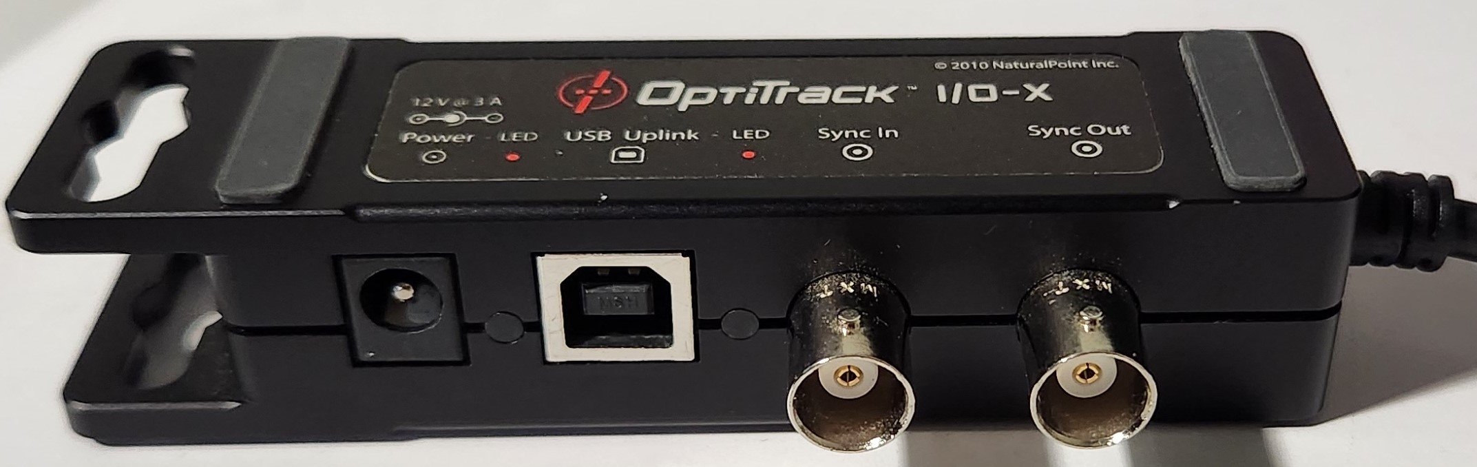
I/O-X (breakout box)
Power adapter and cord
Camera bar cable (attached to I/O-X)
USB Uplink cable
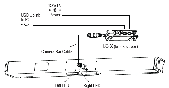
Mount the camera bar in the designated location.
Connect the Camera Bar Cable to the back of the camera and to the I/O-X device, as shown in the diagram above.
Connect the I/O-X device to the PC using the USB uplink cable.
Connect the power cable to the I/O-X device and plug it into a power source.
Make sure the power is disconnected from the I/O-X (breakout box) before plugging or unplugging the Camera Bar Cable. Hot-plugging this cable may damage the device.
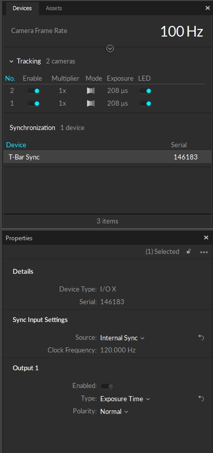
The V120 cameras use a preset frequency for timing and can run at 25 Hz, 50 Hz or 100 Hz. To synchronize other devices with the Duo or Trio, use a BNC cable to connect an input port on the receiving device to the Sync Out port on the I/O-X device.
Output options are set in the Properties pane. Select T-Bar Sync in the Devices pane to change output options:
Exposure Time: Sends a high signal based on when the camera exposes.
Passthrough: Sync In signal is passed through to the output port.
Recording Gate: Low electrical signal (0V) when not recording and a high (3.3V) signal when recording is in progress.
Gated Exposure Time: ends a high signal based on when the camera exposes, only while recording is in progress.
Timing signals from other devices can be attached to the V120 using the I/O-X device's Sync In port and a BNC cable. However, this port does not allow you to change the rate of the device reliably. The only functionality that may work is passing the data through to the output port.
The Sync In port cannot be used to change the camera's frequency reliably.
The V120 ships with a free license for Motive:Tracker installed.
The V120 runs in Precision, Grayscale, and MJPEG modes. Object mode is not available.
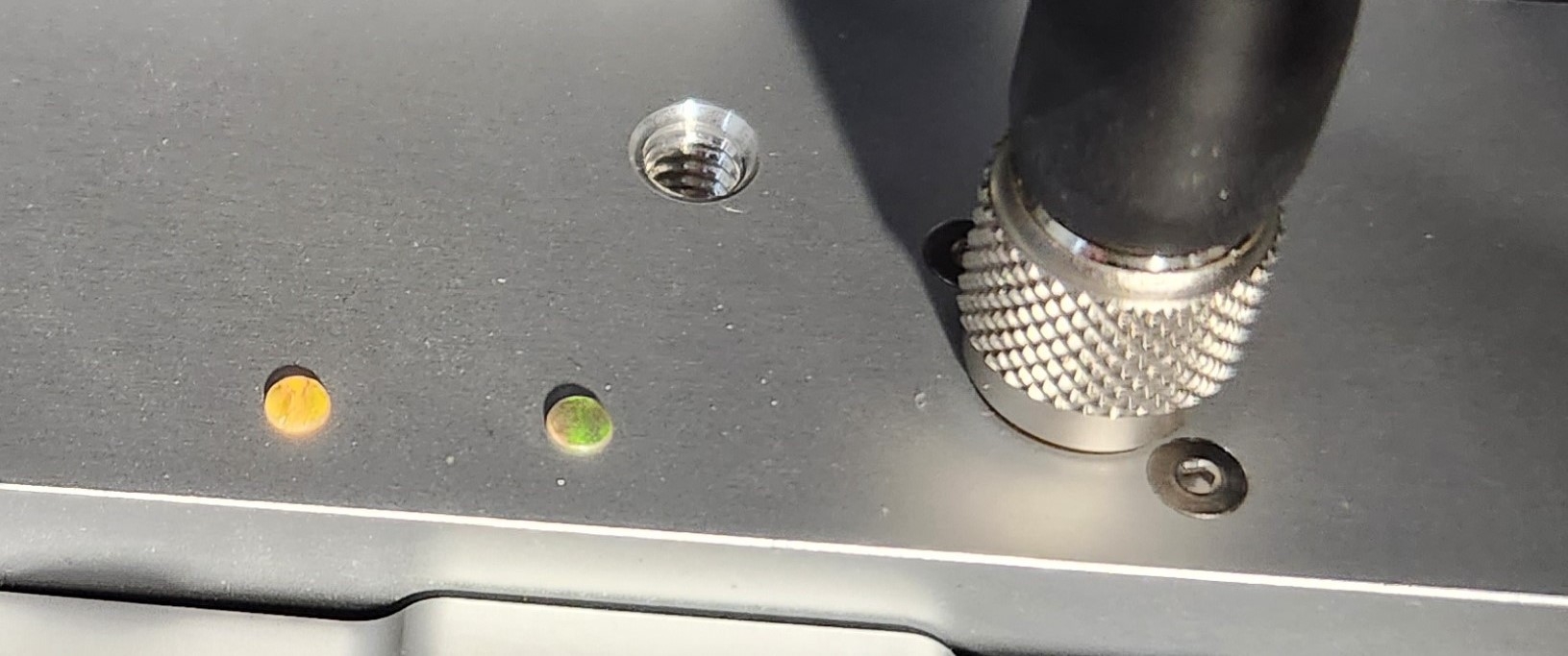
LED lights on the back of the V120 indicate the device's status.
None
Device is off.
Red
Device is on.
Amber
Device is recognized by Motive.
None
Tracking/video is not enabled.
Solid Red
Configured for External-Sync: Sync Not Detected
Flashing Red
Configured for Default, Free Run Mode,
or External-Sync: Sync Detected
Solid Green
Configured for Internal-Sync: Sync Missing
Flashing Green
Configured for Internal-Sync: Sync Present
Download the Motive 3.1 software installer from the to each host PC.
Please see the section of the page for computer specifications.
The camera is pre-calibrated and no wanding is required. The user can .