Data Recording
This page provides an overview of the recording process in Motive.
Overview
Camera data captured in Motive can be streamed live to other applications or recorded into the Take file (.tak) file format. Once recorded, data can be exported from the Take. The Take can also be edited and streamed into other applications.
A Take file includes:
2D Motion Capture data.
3D Solved data.
Reference video, if included during the capture.
Preparing to Record
Before you begin recording, make sure the following items are completed:
Once these items are completed, you are ready to capture Takes.
You can create Skeleton and Rigid Body assets in Live mode prior to recording. Trained Markerset assets require recorded data to capture the asset's full range of motion. These assets are best created in Edit mode, then copied into Live for use in additional captures.
For real-time tracking applications, please see the Data Streaming page.
Live Mode and Edit Mode
Motive has two modes: Live and Edit. The Control Deck contains the operations for recording or playback, depending on which mode is active. Toggle between the two by selecting one from the ![]() button on the Control Deck or by using the Shift + ~ hotkey.
button on the Control Deck or by using the Shift + ~ hotkey.
Tip: Prime series cameras will illuminate in blue when in live mode, in green when recording, and are turned off in edit mode. See more at Camera Status Indicators.
Live Mode
Live mode is used when recording new Takes or when streaming a live capture. In this mode, all enabled cameras continuously capture 2D images and reconstruct the detected reflections into 3D data in real-time.
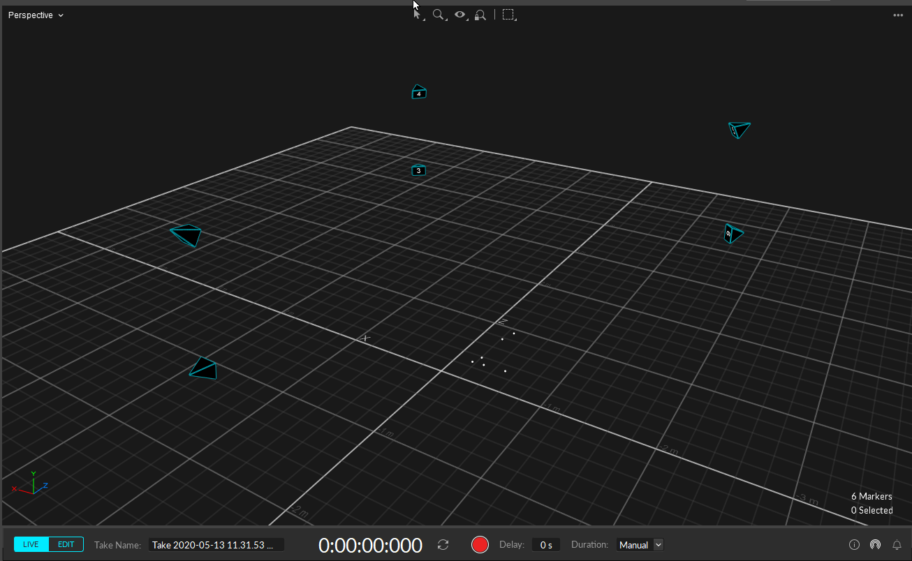
Edit Mode
Edit Mode is used for playback of captured Take files. In this mode, you can playback or stream recorded data and complete post-processing tasks.
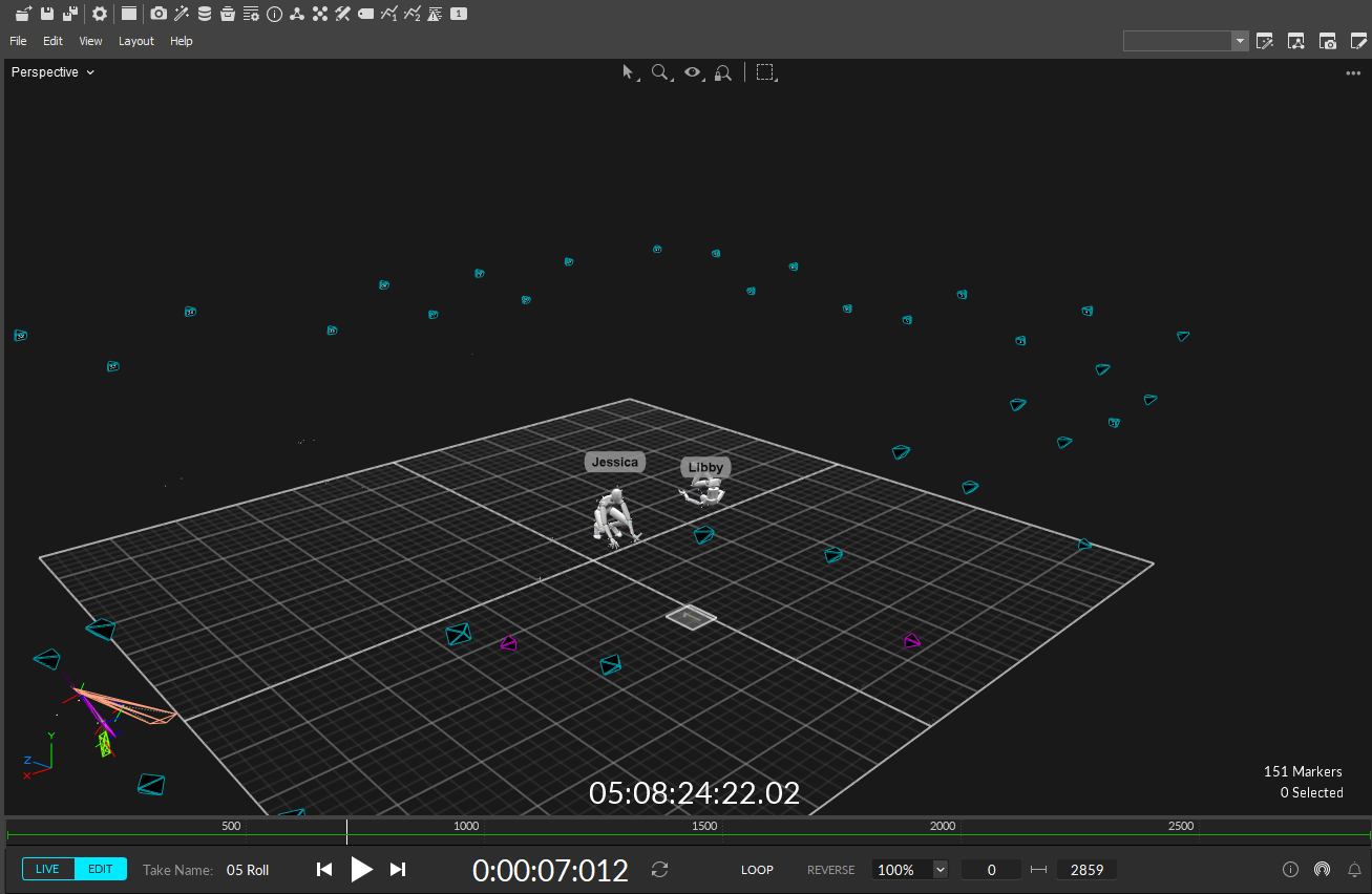
Control Deck
Recording (Live) and playback (Edit) functions are located on the Control Deck at the bottom of the Motive screen. Toggle between the two by selecting one from the ![]() button on the Control Deck or by using the Shift + ~ hotkey.
button on the Control Deck or by using the Shift + ~ hotkey.
Live Mode
When in Live mode, the Control Deck provides controls to:
Change the Take name from the default.
Start or stop recording.
Record for a preset duration of time, or until manually stopped.

Edit Mode
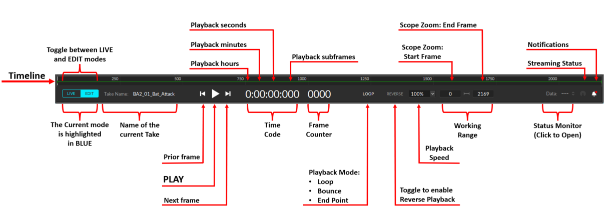
Edit Mode is used for playback of captured Take files. In this mode, you can playback and stream recorded data and complete post-processing tasks. The Cameras View displays the recorded 2D data while the 3D Viewport represents either recorded or real-time processed data as described below.
There are two modes for editing:
Edit: Playback in standard Edit mode displays and streams the processed 3D data saved in the recorded Take. Changes made to settings and assets are not reflected in the Viewport until the Take is reprocessed.
Edit 2D: Playback in Edit 2D mode performs a live reconstruction of the 3D data, immediately reflecting changes made to settings or assets. These changes are not applied to the recording until the Take is reprocessed. To playback in 2D mode, click the Edit button and select Edit 2D.
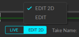
Regardless of the selected Edit mode, you must reprocess the Take to create new 3D data based on the modifications made.
Please see the Data Editing page for more information about editing Takes.
Recording
In Live mode, click the Record Button ![]() on the Control Deck to begin recording. Motive will display a red border around the Viewport and the Cameras View while recording is in progress.
on the Control Deck to begin recording. Motive will display a red border around the Viewport and the Cameras View while recording is in progress.
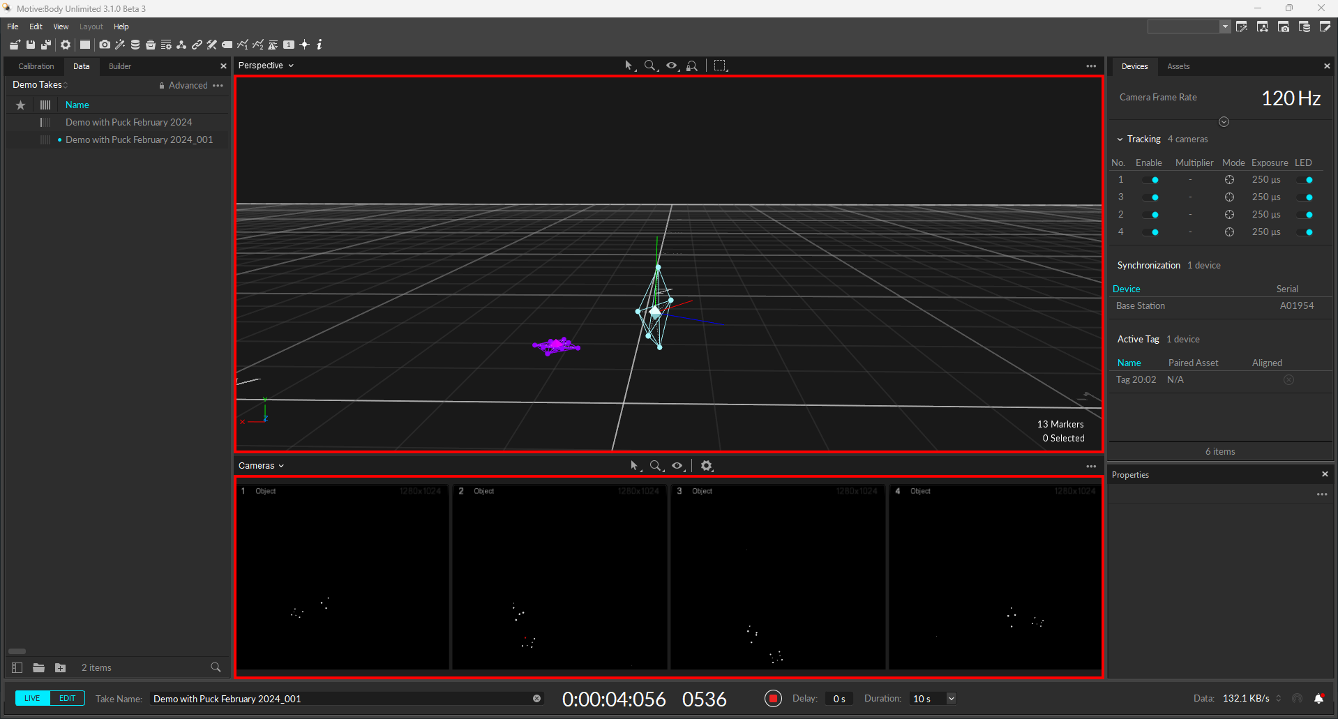
When using a preset duration timer, Motive will stop recording once the timer runs out. When the duration is set to Manual, click the Stop button ![]() to end the recording.
to end the recording.
Recording Delay
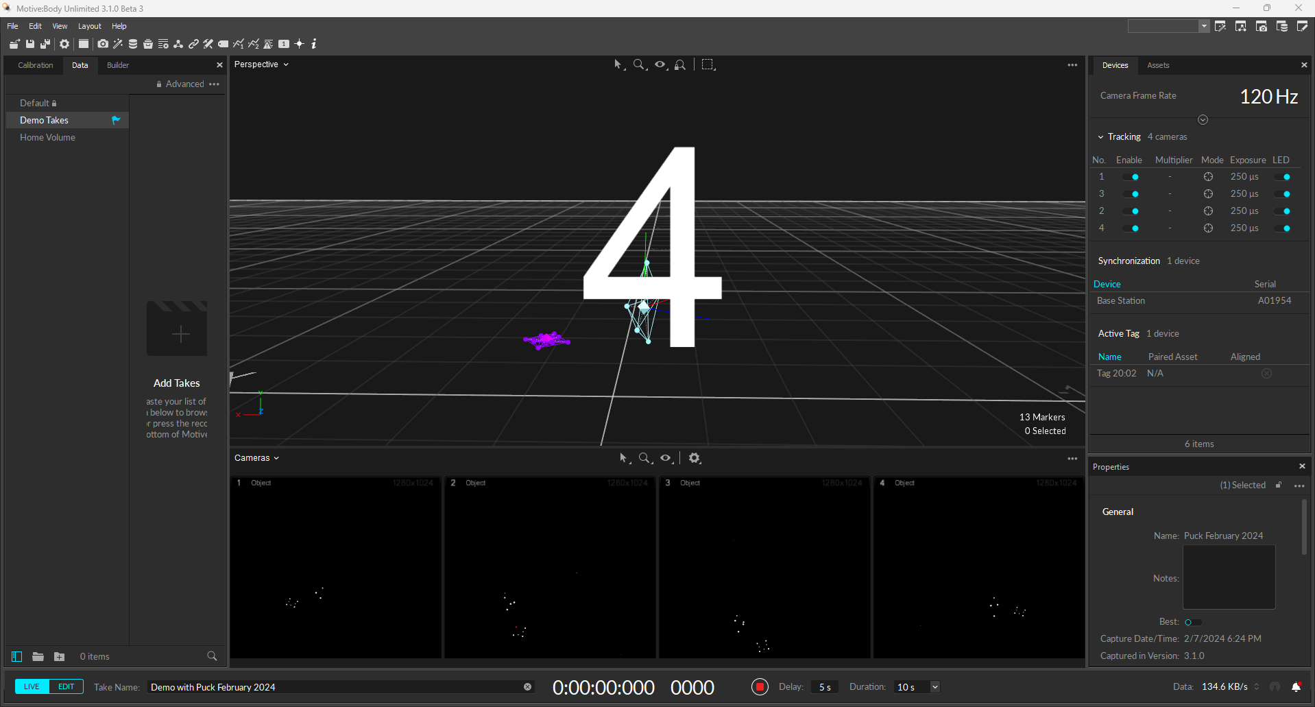
The Recording Delay feature adds a countdown before the start of the capture, allowing time to set the scene and ensure all actors are in place.
Recorded Data Management
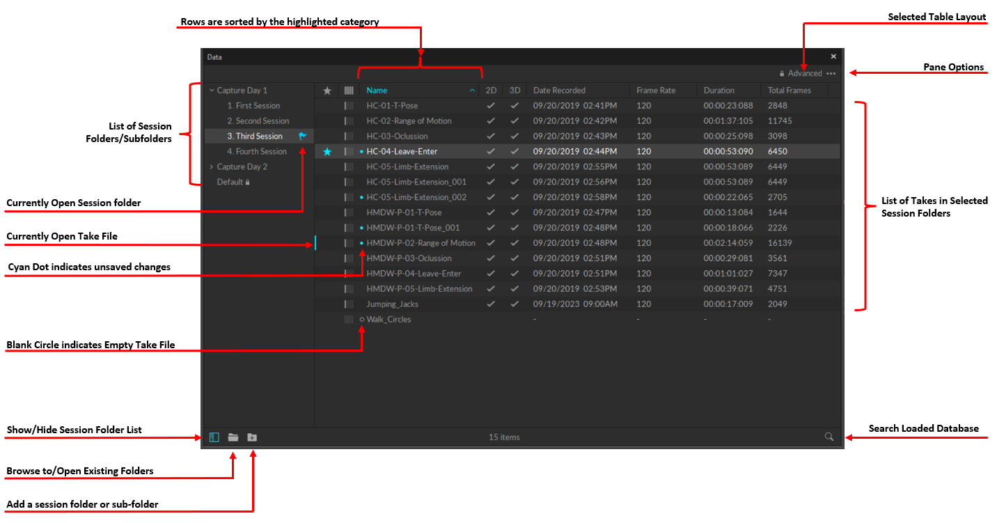
In Motive, Take file are stored in folders known as session folders.
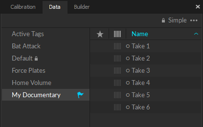
The Data pane is the primary interface for managing capture files. It displays a list of session folders and the corresponding Take files that are recorded or loaded in Motive.
Open the Data pane by clicking the ![]() icon on the main Toolbar.
icon on the main Toolbar.
Tips for Managing Takes
Always start by creating session folders for organizing related Takes (e.g., name of the tracked subject). Click the
 button at the bottom of the pane to create a new folder.
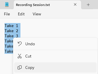
 Plan ahead for the capture day by creating a list of captures in a text file or a spreadsheet. Copy and paste (Ctrl + V) the list into the Data Management pane to create empty Takes as placeholders for the shoot. (e.g. walk, jog, run, jump).
Start the capture day with a training Take for each Trained Markerset. Once the Markerset assets are created, they can be imported into Live and included in the remaining captures.
Select one of the empty Takes and start recording. Motive will save the capture using the same name as the selected Take.
If the capture was unsuccessful, simply record it again. Motive will record additional Takes with an incremented suffix added to the given Take name (e.g. walk_001, walk_002, walk_003). The suffix format is defined on the General tab of the Application Settings panel.
When the capture is successful, select another empty Take in the list to begin the next capture.
To close an individual session folder, right-click on the folder and select Remove.
To close all the open session folders at once, right-click in the empty space in the session folder list and select Remove all Folders.
Recorded Data Types
When a capture is recorded, both 2D data and real-time reconstructed 3D data are saved in the Take. For more details on each data type, refer to the Data Types page.
2D data: Consists of the 2D object images captured by each camera.
3D data: Reconstructed 3D marker data, solved from the 2D data.
Reference Video from Prime Color cameras or from mocap cameras running in MJPEG mode is also included in the Take.
Marker Types in Motive
In the 3D perspective view, marker data displays the 3D positions of the actual markers, as calculated from the camera data. This is distinct from the position of marker constraints in the solver calculation for any assets that include the selected markers.
Markers can be Passive or Active, Labeled or Unlabeled.
To customize the color associated with a specific marker type, click ![]() to open the Applications Setting panel. Marker settings are located on the Views tab. Asset markers will display in the color set in the asset properties.
to open the Applications Setting panel. Marker settings are located on the Views tab. Asset markers will display in the color set in the asset properties.
Markers associated with Rigid Bodies, Skeletons, or Trained Markersets will use the color properties of the asset rather than the application defaults.
For more detail on markers, please see the Markers page.
Passive and Active Markers
Passive Markers have a retroreflective covering that reflects incoming light back to its source. IR light emitted from the camera is reflected by passive markers, detected by the camera’s sensor, and captured as 2D marker data.
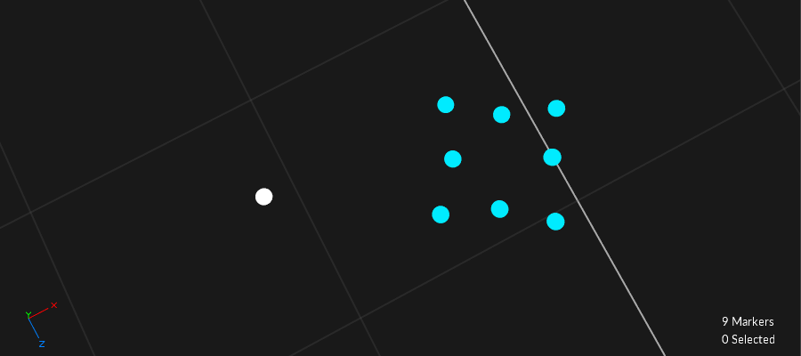
Passive markers that are not part of an asset are white by default.
Active Markers emit a unique LED pulse in sync with a BaseStation for optimal tracking. Active markers are reconstructed and tracked in Motive automatically. The unique illumination pattern ensures each active marker is individually labeled, with an Active ID assigned to the corresponding reconstruction. This applies whether or not the Active Marker is part of an asset.
Active markers that are not part of an asset are cyan by default.
Labeled and Unlabeled Markers
Marker labels are software tags assigned to identify trajectories of reconstructed 3D markers so they can be referenced for tracking individual markers, Rigid Bodies, Skeletons, or Trained Markersets. When an asset is created, the markers used to define it are automatically labeled as part of the asset definition.
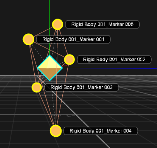
To display Marker Labels in the 3D Viewport, click the ![]() Visual Aids button and select Labels from the Marker section of the menu. Alternately, use the hotkey L to toggle labels on or off.
Visual Aids button and select Labels from the Marker section of the menu. Alternately, use the hotkey L to toggle labels on or off.
Select Simplify Labels (or use hotkey Ctrl + L) to display the marker label without the asset name prefix.
Unlabeled Markers
Markers that are not part of an asset remain unlabeled and are displayed in the 3D Viewport using the selected color values in Applications Settings.
Unlabeled Markers can also result from tracking errors that occur during the capture, such as marker occlusions. You can do another Take, or address labeling errors in post-processing. Please see the Data Editing and Labeling pages for more detail on this process.
Marker color can also be changed through the Constraints XML file if needed.
Marker Constraints
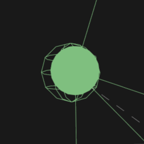
The reconstructed 3D markers that comprise an asset are known as Constraints in Motive. They appear as transparent spheres that reflect the expected position of a 3D marker in the solved data, based on the asset definition.
To view Marker Constraints, select Marker Constraints from the Visual Aids ![]() menu in the viewport and select Show All.
menu in the viewport and select Show All.
For more information about working with Constraints, please see the Constraints Pane page.
Was this helpful?

