LogoLogo
WebsiteSupportDownloadsForumsQuick LinksContact Us
v3.2
v3.2
  • OptiTrack Documentation
  • WHAT'S NEW
    • What's New in Motive 3.2
  • QUICK START GUIDES
    • Quick Start Guide: Getting Started
    • Quick Start Guide: Prime Color Camera Setup
    • Quick Start Guide: Precision Capture
    • Quick Start Guide: Tutorial Videos
    • Quick Start Guide: Active Marker Tracking
    • Quick Start Guide: Outdoor Tracking Setup
  • HARDWARE
    • Cameras
      • Ethernet Cameras
        • PrimeX 120
        • PrimeX 41
        • PrimeX 22
        • PrimeX 13
        • PrimeX 13W
        • SlimX 13
        • Prime Color
        • VersaX 22
        • VersaX 41
        • VersaX 120
      • USB Cameras
        • Slim 3U
        • Flex 13
        • Flex 3
        • V120:Duo
        • V120:Trio
        • Adjusting Global Origin for Tracking Bars
    • Prepare Setup Area
    • Camera Mount Structures
    • Camera Placement
    • Ethernet Camera Network Setup
      • General Overview and Specs
      • Windows 10 Network Settings
      • Cabling and Load Balancing
      • Switch Configuration for PrimeX 120
      • NETGEAR ProSafe GSM7228S: Disabling the Broadcast Storm Control
      • White/Blacklisting Cameras
    • USB Camera System Setup
      • USB Camera Network Overview and Specs
      • V120:Duo and Trio Setup
      • Tracking Bar Coordinate System
        • Transforming Coordinate System: Global to Local
    • Aiming and Focusing
    • Camera Status Indicators
  • MOTIVE
    • Installation and License Activation
    • Motive Basics
    • Calibration
      • .mcal XML Calibration Files
      • Continuous Calibration
      • Continuous Calibration (Info Pane)
      • Calibration Squares
    • Markers
    • Assets
      • Gizmo Tool: Translate, Rotate, and Scale
    • Rigid Body Tracking
      • Aligning Rigid Body Pivot Point with a Replicated 3D Model
    • Skeleton Tracking
    • Trained Markersets
    • IMU Sensor Fusion
    • Data Recording
      • Data Types
    • Labeling
    • Data Editing
    • Data Export
      • Data Export: BVH
      • Data Export: C3D
      • Data Export: CSV
      • Data Export: FBX
      • Data Export: TRC
    • Data Streaming
    • Camera Video Types
    • Audio Recording
    • Motive HotKeys
    • Measurement Probe Kit Guide
    • Motive Batch Processor
    • Reconstruction and 2D Mode
  • MOTIVE UI PANES
    • Settings
      • Settings: General
      • Settings: Assets
      • Settings: Live Pipeline
      • Settings: Streaming
      • Settings: Views
      • Settings: Mouse and Keyboard
      • Settings: Audio
    • Assets Pane
    • Builder Pane
    • Constraints Pane
      • Constraints XML Files
    • Calibration Pane
    • Data Pane
    • Devices Pane
    • Edit Tools Pane
    • Graph View Pane
    • Info Pane
    • Labels Pane
    • Log Pane
    • Probe Pane
    • Properties Pane
      • Properties Pane: Camera
      • Properties Pane: Force Plates
      • Properties Pane: NI-DAQ
      • Properties Pane: OptiHub2
      • Properties Pane: Rigid Body
      • Properties Pane: Skeleton
      • Properties Pane: Take
      • Properties Pane: Trained Markerset
      • Properties Pane: eSync2
    • Status Panel
    • Toolbar/Command Bar
    • Control Deck
    • Viewport
  • PLUGINS
    • OptiTrack Blender Plugin
      • OptiTrack Blender Plugin
    • OptiTrack Unreal Engine Plugin
      • Unreal Engine: OptiTrack Live Link Plugin
        • Quick Start Guide: Real-Time Retargeting in Unreal Engine with Live Link Content
        • Unreal Editor for Fortnite (UEFN): OptiTrack Plugin for Live Link Hub
        • Unreal Engine: Live Link Camera Stream Setup
        • Live Link Content: Active Puck Static Meshes
      • Unreal Engine: MotionBuilder Workflow
      • Unreal Engine: HMD Setup
      • Unreal Engine VCS Inputs
    • OptiTrack Unity Plugin
      • Unity: HMD Setup
    • OptiTrack OpenVR Driver
    • OptiTrack MATLAB Plugin
    • Autodesk Maya
      • Autodesk Maya: OptiTrack Insight VCS Plugin
    • Autodesk MotionBuilder
      • Autodesk MotionBuilder Plugin
      • Autodesk MotionBuilder: OptiTrack Skeleton Plugin
      • Autodesk MotionBuilder: OptiTrack Optical Plugin
      • Autodesk MotionBuilder: OptiTrack Insight VCS Plugin
      • Autodesk MotionBuilder: Timecode Data
    • OptiTrack Peripheral API
    • External Plugins
      • Houdini 19 Integration
  • ACTIVE COMPONENTS
    • Active Components Hardware
      • Active Puck
      • Wired AnchorPuck
      • CinePuck
      • Wired CinePuck
      • BaseStation
      • Information for Assembling the Active Tags
      • Manus Glove Setup
    • Configuration
      • Active Batch Programmer
      • Active Hardware Configuration: PuTTY
      • Active Component Firmware Compatibility
    • Active Marker Tracking
      • Active Finger Marker Set
  • SYNCHRONIZATION
    • Synchronization Hardware
      • External Device Sync Guide: eSync 2
      • External Device Sync Guide: OptiHub2
    • Synchronization Setup
    • OptiTrack Timecode
  • VIRTUAL PRODUCTION
    • Unreal Engine: OptiTrack InCamera VFX
    • Entertainment Marker Sets
    • PrimeX 41
  • MOVEMENT SCIENCES
    • Movement Sciences Hardware
      • General Motive Force Plate Setup
      • AMTI Force Plate Setup
      • Bertec Force Plate Setup
      • Kistler Force Plate Setup
      • Delsys EMG Setup
      • NI-DAQ Setup
      • Multiple Device Setup
    • Movement Sciences Marker Sets
      • Biomechanics Marker Sets
      • Biomech (57)
      • Rizzoli Marker Sets
    • For Visual3D Users
    • Prime Color Camera Setup
      • Prime Color Setup: Required Components
      • Prime Color Setup: Hardware Setup
      • Prime Color Camera Setup: Camera Settings
      • Prime Color Camera Setup: Prime Color FS Calibration
      • Prime Color Setup: Data Recording / Export
      • Prime Color Camera Setup: FAQ / Troubleshooting
      • Prime Color Camera Setup: Windows Network Settings
  • VIRTUAL REALITY
    • VR Plugins
      • VR Unreal Engine
        • OptiTrack Unreal Engine Plugin
        • Unreal Engine: OptiTrack Live Link Plugin
          • UE5.1 Live Link Retarget External Workaround
        • Unreal Engine VCS Inputs
      • VR Unity
        • OptiTrack Unity Plugin
      • VR OpenVR
        • OptiTrack OpenVR Driver
    • VR HMD Setup
      • Unreal Engine: HMD Setup
      • Unity: HMD Setup
      • Manually Calibrating the HMD Pivot Point
      • Sync Configuration with an HTC Vive System
    • SlimX 13
    • Active Marker Tracking
      • Active Finger Marker Set
    • Synchronization Hardware
      • External Device Sync Guide: eSync 2
      • External Device Sync Guide: OptiHub2
  • ANIMATION
    • Autodesk Maya
      • Autodesk Maya: OptiTrack Insight VCS Plugin
    • Autodesk MotionBuilder
      • Autodesk MotionBuilder Plugin
      • Autodesk MotionBuilder: OptiTrack Skeleton Plugin
      • Autodesk MotionBuilder: OptiTrack Optical Plugin
      • Autodesk MotionBuilder: OptiTrack Insight VCS Plugin
      • Autodesk MotionBuilder: Timecode Data
  • ROBOTICS
    • MoCap4ROS2 Setup
    • OptiTrack Robot Applications
    • Outdoor Tracking Setup
  • DEVELOPER TOOLS
    • Developer Tools Overview
    • Camera SDK
      • Class: cCameraModule
      • Class: cUID
    • Motive API
      • Motive API: Quick Start Guide
      • Motive API Overview
      • Motive API: Function Reference
      • Motive API Camera Calibration
    • NatNet SDK
      • NatNet 4.1
      • NatNet: Class/Function Reference
      • NatNet: Creating a Managed (C sharp) Client Application
      • NatNet: Creating a Native (C++) Client Application
      • NatNet: Data Types
      • NatNet: Matlab Wrapper
      • NatNet: Migration to NatNet 3.0 libraries
      • NatNet: Remote Requests/Commands
      • NatNet: Sample Projects
      • NatNet: Unicast Data Subscription Commands
      • Latency Measurements
    • VRPN Sample
    • Peripheral API: Glove Devices
  • SKELETON MARKER SETS
    • Full Body
      • Baseline (41)
      • Core (50)
      • Biomech (57)
      • Conventional (39)
    • Full Body + Fingers
      • Baseline + Passive Fingers (49)
      • Baseline + Active Fingers (57)
      • Core + Passive Fingers (54)
      • Core + Active Fingers (62)
    • Upper
      • Baseline Upper (25)
      • Conventional Upper (27)
    • Lower
      • Baseline Lower (20)
      • Helen Hayes Lower (19)
      • Conventional Lower (16)
    • Hand and Fingers
      • Left/Right Hand (4) Active
      • Left/Right Hand (10) Active + Passive
      • Active Finger Marker Set
    • Glove Device Setup
      • Manus Glove Setup
      • StretchSense Glove Setup
    • Rizzoli Marker Sets
    • Entertainment Marker Sets
    • Rigid Body Skeleton Marker Set
  • GENERAL TROUBLESHOOTING
    • Licensing Troubleshooting
    • Windows 11 Optimization for Realtime Applications
    • Network Troubleshooting
    • Troubleshooting Q&A
    • Running Motive on High DPI Displays
    • Firewall Settings
Powered by GitBook
On this page
  • Arm Follower Demo Using the Hiwonder JetMax Arm
  • About this Demo
  • Setup Requirements
  • Required Hardware
  • Required Software
  • Connect Hardware
  • Ubuntu Companion Computer Configuration
  • JetMax Computer Configuration
  • OptiTrack Configuration
  • Run the Program
  • Issues and Possible Improvements

Was this helpful?

Export as PDF
  1. ROBOTICS

MoCap4ROS2 Setup

Learn how to use an OptiTrack system to control a robotic arm.

PreviousROBOTICSNextOptiTrack Robot Applications

Last updated 6 months ago

Was this helpful?

Arm Follower Demo Using the Hiwonder JetMax Arm

This demo uses the mocap4ros2_optitrack package to configure the Hiwonder JetMax arm's end effector to follow an arbitrary rigid body using OptiTrack cameras and Motive software.

See our document for robotics use case examples.

The source code for this tutorial is located at .

About this Demo

This demo provides an example workflow to use an OptiTrack system to control a robotic arm. The demo uses a 3DOF robot arm, the Hiwonder JetMax. This robot was selected for its affordability, desktop size, and ROS2 support, with minimal setup required to get up and going. The provided packages from work well out of the box.

The package provided by Hiwonder to control the arm with a python package, , can also be adapted into a ROS package fairly easily.

While the scope of this example is limited to the specified hardware, similar concepts should work with other robotic arms.

Setup Requirements

Required Hardware

  • A computer capable of running Motive and at least 3 OptiTrack cameras to serve as the Motive PC. Please see the section of the page.

  • A second computer running Ubuntu 20.04 or greater (the Ubuntu companion computer). Use a separate PC rather than an instance of WSL2 on the Motive PC. For more information, please see the section , below.

  • A .

  • Two and a .

  • A router or switch with an internet connection, separate from the OptiTrack switch.

  • A second Network Interface Card (NIC) for the Motive PC, to connect to the Arm Follower network.

  • An ethernet cable to connect the JetMax to the internet-connected router.

Required Software

  • Motive 3.1 (or above), installed on the Host PC.

  • jetmax_optitrack_feedback package, installed on the JetMax's Jetson Nano.

  • mocap4ros2_optitrack, installed on the Ubuntu Companion computer (originally from https://github.com/OptiTrack/mocap4ros2_optitrack).

  • mocap_msgs, installed on the Ubuntu Companion computer (originally from https://github.com/OptiTrack/mocap_msgs).

  • tf_repub, installed on the Ubuntu Companion computer.

Connect Hardware

This system requires two separate networks, using independent switches, to function:

  • One switch to network the JetMax, Ubuntu Companion Computer, and Motive PC. This switch can optionally be connected to the internet.

The diagram below shows how to network the necessary devices together:
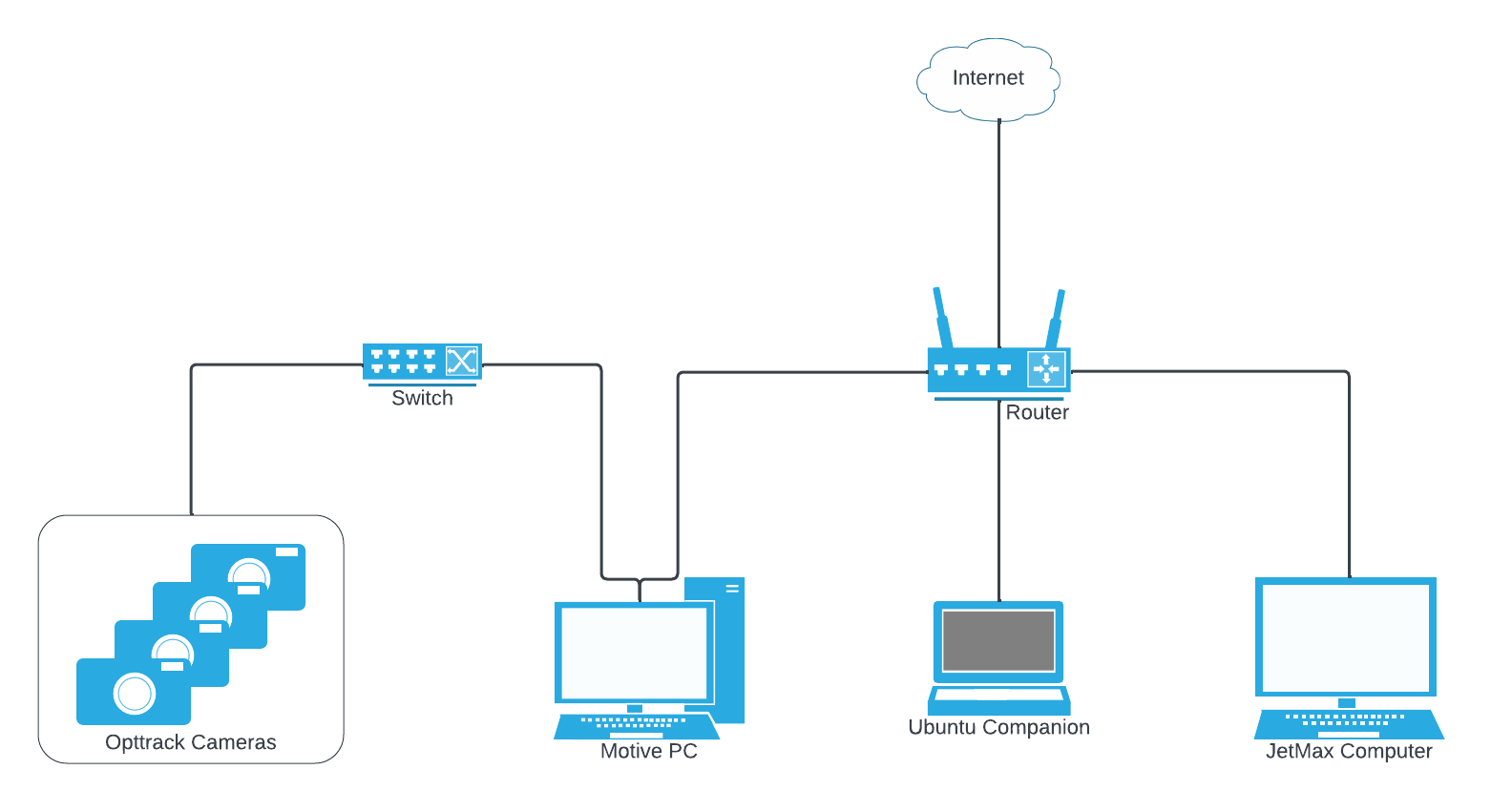
The Ubuntu companion computer is required to pass data from the Motive PC to the JetMax.

Ubuntu Companion Computer Configuration

We tested using Ubuntu 22.04 with ROS2 Iron. Ubuntu 20.04+ with ROS2 Foxy or newer should also work adequately.

ROS2 versions are dependent on your OS so pay attention to the version you install.

Create Package and Setup Config Files

cd ~
git clone https://github.com/OptiTrack/robot_arm_follower_demo.git
mkdir -p ~/optitrack_companion_ws/src
cd ~/optitrack_companion_ws/src
# copy mocap_msgs, mocap4ros2_optitrack, and tf_repub to the src directory
cp -r ~/robot_arm_follower_demo/packages_on_ubuntu_companion/* ~/optitrack_companion_ws/src
cd ~/optitrack_companion_ws
source /opt/ros/<your-ros-distro>/setup.bash
colcon build

If the build was successful, the optitrack_companion_ws will be populated with build, install, and log directories.

JetMax Computer Configuration

There are two methods for operating the Jetson Nano on the JetMax robot:

  1. Using the SD card image that ships with the JetMax, running Ubuntu 18.04.

While Ubuntu 18.04 is no longer a supported OS, it is the most recent Ubuntu version that NVIDIA supports for the JetMax. You may be able to run the JetMax using a more recent version of Ubuntu, however that configuration will not be supported by NVIDIA.

Install Ubuntu 18.04

  1. Reflash the SD following the SD card Getting Started guide from Nvidia

  2. Download the jetson expansion board access package on the home directory and install:

    git clone https://github.com/JetMaxRoboticArm/jetmax_ebap.git
    cd jetmax_ebap
    python3 setup.py install
  3. If permission errors persist, use the chmod or adduser commands to update or add access.

While ROS2 Foxy is no longer a supported version, it is the version required for Ubuntu 18.04.

To run the entire system on the JetMax, either:

  1. Update the OS

  2. Develop a solution to use tf2_ros. Perhaps use a C++ executable after building tf2 from source or figure out how to install the tf2_ros python package.

  3. Rtun the system without using tf2 messages.

Build the Code

Create the package and setup configuration files.

cd ~
git clone https://github.com/OptiTrack/robot_arm_follower_demo.git
mkdir -p ~/optitrack_robot_ws/src
cd ~/optitrack_robot_ws/src
# copy mocap_msgs, mocap4ros2_optitrack, and tf_repub to the src directory
cp -r ~/robot_arm_follower_demo/packages_on_jetmax/* ~/optitrack_robot_ws/src
cd ~/optitrack_robot_ws
source /opt/ros/<your-ros-distro>/setup.bash
colcon build

OptiTrack Configuration

For an easier setup process, keep track of the orientation of the calibration square during the initial configuration. The orientation of the JetMax should match the following image when using a calibration square:
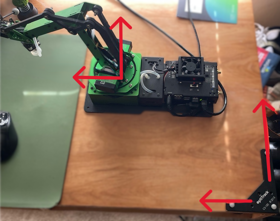
Create Rigid Bodies

Create two rigid bodies:

  • end_effector - mount this to the end effector of the arm.

  • base_link - place this near the robot arm. The exact position or how the rigid body is attached does not matter as long as it's secured and visible to the cameras.

Enable NatNet Streaming

  • Click to enable NatNet streaming.

  • Set the local interface to an IP on the same network as the Ubuntu Companion computer.

Run the Program

With Motive streaming, launch the Ubuntu Companion Computer:

# terminal 1
cd ~/optitrack_companion_ws
source install/setup.bash
ros2 launch mocap_optitrack_driver optitrack2.launch.py
# terminal 2
cd ~/optitrack_companion_ws
source install/setup.bash
ros2 run tf_repub transform_republisher

Launch the JetMax Arm.

We recommend using SSH to connect to the JetMax for this step.

# terminal 1
cd ~/optitrack_robot_ws
source install/setup.bash
ros2 run jetmax_optitrack_feedback jetmax_feedback_node

Ensure the base_link rigid body is near the robot.

# terminal 2
cd ~/optitrack_robot_ws
source install/setup.bash
ros2 topic pub /get_target_pos std_msgs/msg/Bool "data: True" --once

Start moving the base link rigid body to have the robot follow!

What is going on?

In this demo, the JetMax maintains a static distance between its end effector and the target rigid body. This is done by constantly measuring the distance between the end_effector and base_link Rigid Bodies with OptiTrack. The robot sees the change in distance and adjusts its position to compensate.

Take a look at the links provided to learn more about locomotion for a robot arm using ROS.

Issues and Possible Improvements

Need for Companion Computer

The Ubuntu companion computer is needed because the NatNet binary is not yet available for ARM devices. This means that the mocap4ros2_optitrack package had to run on a computer that did not have an ARM architecture.

When the ARM library for NatNet becomes available, mocap4ros2_optitrack will run on an ARM device and a companion computer will no longer be needed.

Unable to use WSL2

The mocap4ros2_optitrack plugin could run on a WSL2 standalone PC because Motive and the WSL2 instance can easily exist on the network created by the windows host.

Orientation of the JetMax

The orientation of the JetMax should not need to be fixed. Ideally, in the future, a few markers placed on the base of the robot would allow the calculated target position to account for the orientation of the robot instead of assuming orientation.

Visit the page for the following software packages:

The OptiTrack camera network, with only the cameras and the Motive PC connected. For more details about configuring the camera network, please see the chapter.

Please see the section , below, for more information.

Some familiarity with ROS will help in later steps. are available from the docs.ros.org website.

For installation instructions for Ubuntu 22.04, please see

Using an SD card image with a fresh install of supported by NVIDIA.

If using the SD card image that ships with the JetMax, skip to the section.

Test access to the board using the . If you receive permissions errors, try using sudo python3 before running commands to see if this allows you to access the GPIO.

Install ROS2 Foxy from .

For our testing, we flashed the SD card with the official , which contains Ubuntu 18.04, a version that is end of life and losing support. We installed ROS2 Dashing and, because it is losing support, transform (tf2) messages are not supported. We implemented a workaround to republish the tf2 messages with tf_repub package installed on the Ubuntu companion computer.

Please see our for detailed instructions to setup an OptiTrack camera system and install the Motive software.

For instructions to create rigid bodies, please see the page.

For a detailed overview of streaming, please see the pages in our .

Click the streaming button in the lower right corner of the Motive Control Deck to open the panel to the .

The program issues a to the robot, then an engine computes the for the robot given a .

A more comprehensive example of Standard ROS practice can be found here:

The Ubuntu companion computer cannot be a WSL2 instance of the Windows host running Motive because it is difficult to network the WSL2 instance to be on the same LAN as the robot arm computer. By default, the network of the WSL2 instance is a NAT subset defined by the host windows machine. This link may be useful for giving a static IP on the same network as the Windows host, although this is untested:

OptiTrack Downloads
Ethernet Camera Network Setup
Tutorials for using ROS2 Iron
https://docs.ros.org/en/humble/Installation/Ubuntu-Install-Debians.html
Ubuntu 18.04
jetmax_ebap readme
https://docs.ros.org/en/foxy/Installation.html
image for the Jetson Nano
Quick Start Guide
Rigid Body Tracking
NatNet chapter
cartesian control command
inverse kinematics
target joint angles
description of the robot's mechanics
Universal_Robots_ROS2_Gazebo_Simulation
assigning-static-ip-addresses-in-wsl2.md
Need for companion computer
Build the Code
OptiTrack Robot Applications
OptiTrack/mocap4ros2_optitrack_demos
JetMaxRoboticArm
jetmax_ebap
Installation and License Activation
JetMax Hiwonder Robot
rigid bodies
calibration square
Unable to Use WSL2
Applications Settings
Streaming tab
Networking configuration.
JetMax oriented with the calibration square.
Host PC Requirements