Motive Basics
Everything you need to know to move around the Motive interface.
This page provides an overview of Motive's tools, configurations, navigation controls, and instructions on managing capture files. Links to more detailed instructions are included.
File Management
In Motive, motion capture recordings are stored in the Take (.TAK) file format in folders known as session folders.
The Data pane is the primary interface for managing capture files. Open the Data pane by clicking the ![]() icon on the main Toolbar to see a list of session folders and the corresponding Take files that are recorded or loaded in Motive.
icon on the main Toolbar to see a list of session folders and the corresponding Take files that are recorded or loaded in Motive.
Take Files (.TAK)
A .TAK file is a single motion capture recording (aka 'take' or 'trial'), which contains all the information necessary to recreate the entire capture, including camera calibration, camera 2D data, reconstructed and labeled 3D data, data edits, solved joint angle data, tracking models (Skeletons, Rigid Bodies, Trained Markersets), and any additional device data (audio, force plate, etc.). A Motive take (.TAK) file is a completely self-contained motion capture recording, that can be opened by another copy of Motive on another system.
Take files are forward compatible, but not backwards compatible, meaning you can play a take recorded in an older version of Motive in a newer version but not the other way around.
For example, if you try to play a take in Motive 2.x that was record in Motive 3.x, Motive will return an error. You can, however, record a Motive 2.x take and play it back in Motive 3.x.
If you have old recordings from Motive 1.7 or below, with .BAK file extensions, import them into Motive 2.0 and re-save them into the .TAK file format to open them in Motive versions 3.0 and above.
Session Folders
The folder where take files are stored is known as a session folder in Motive. Session folders allow you to plan shoots, organize multiple similar takes (e.g. Monday, Tuesday, Wednesday, or Static Trials, Walking Trials, Running Trials, etc.) and manage complex sets of data within Motive or Windows.
For a most efficient workflow, plan the mocap session before the capture and organize a list of captures (shots) to be completed. Type the take names in a spreadsheet or a text file, then copy and paste the list into the data pane. This will create empty takes (a shot list) with corresponding names from the pasted list.
Click the ![]() button on the toolbar at the bottom of the Data pane to hide or expand the list of open Session Folders.
button on the toolbar at the bottom of the Data pane to hide or expand the list of open Session Folders.
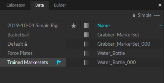
Alternately, with the session folder list closed, click the name of the current session folder in the top left corner for a quick selection.
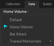
The active Session Folder is noted with a ![]() flag icon. To switch to a different folder, left-click the folder name in the Session list.
flag icon. To switch to a different folder, left-click the folder name in the Session list.
Please refer to the Session Folders section of the Data pane page for more information on working with these folders.
Motive User Profile (.MOTIVE)
Software configuration settings are saved in the motive profile (*.motive) file, located by default at:
C:\ProgramData\OptiTrack\MotiveProfile.motive
The profile includes application-related settings, asset definitions, and the open session folders. The file is updated as needed during a Motive session and at exit, and loads again the next time Motive is launched.
The profile includes:
Application Settings
Live Pipeline Settings
Streaming Settings
Synchronization Settings
Export Settings
Rigid Body & Skeleton assets
Rigid Body & Skeleton settings
Labeling settings
Hotkey configuration
Profile files can be exported and imported, to maintain the same software configuration and asset definitions. This is helpful when the profile is specific to a project and the configuration and assets need to be used on different computers or saved for future use.
Please see the Export Assets Definition section of the Data Export page for more details.
Reset Settings
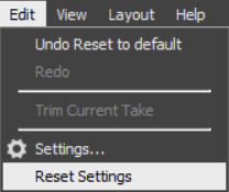
To revert all settings to Motive factory defaults, select Reset Application Settings from the Edit menu.
Calibration files (.CAL)
A calibration file is a standalone file that contains all the required information to restore a calibrated camera volume, including the position and orientation of each camera, lens distortion parameters, and camera settings. After a camera system is calibrated, the .CAL file can be exported and imported back into Motive again when needed. For this reason, we recommend saving the camera calibration file after each round of calibration.
Reconstruction settings are also stored in the calibration file, in addition to the .MOTIVE profile. If the calibration file is imported after the profile file is loaded, the calibration may overwrite the previous reconstruction settings during import.
Note that an imported .CAL file is reliable only if the camera setup has remained unchanged since the calibration. Read more from the Calibration page.
The calibration file includes:
Reconstruction settings
Camera settings
Position and orientation of the cameras
Location of the global origin
Lens distortion of each camera
Default System Calibration
The default system calibration is saved at: C:\ProgramData\OptiTrack\Motive\System Calibration.cal
This file is loaded at startup to provide instant access to the 3D volume. The .CAL file is updated each time the calibration is modified or when closing out of Motive.
Viewports
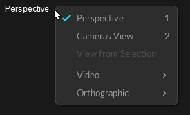
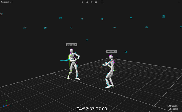
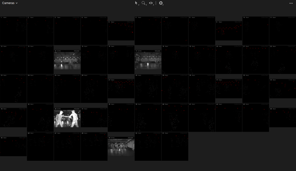
In Motive, the main viewport is fixed at the center of the UI and is used to monitor the 2D or 3D capture data in both live capture and playback of recorded data. The viewports can be set to either Perspective View, which shows the reconstructed 3D data within the calibrated 3D space, or Cameras View, which shows 2D images from each camera in the system. These views can be selected from the drop-down menu at the top-right corner. By default, the Perspective View opens in the top pane and the Cameras view opens in the bottom pane. Both views are essential for assessing and monitoring the tracking data.
Perspective View - 3D
Click on any viewport window and use the hotkey 1 to quickly switch to the Perspective view.
Displays the reconstructed 3D representation of the capture.
Used to analyze marker positions, view rays used in reconstruction, create assets, etc.
The Visual Aids menu
 allows you to select which data to display.
Cameras View - 2D
Click on any viewport window and use the hotkey 2 to quickly switch to the Cameras View.
This view displays the images transmitted from each camera, with a header that shows the camera's Video Mode (Object, Precision, Grayscale, or MJPEG) and resolution.
Detected IR lights and reflections also show in this pane. Only IR lights that satisfy the object filters are identified as markers. See Cameras Basic Settings in the Settings: Live Pipeline page for more detail on object filters.
Includes tools to report camera information, inspect pixels, troubleshoot markers, and mask pixel regions to exclude them from processing. See Cameras View in the Viewport page for more details.
Additional Viewports
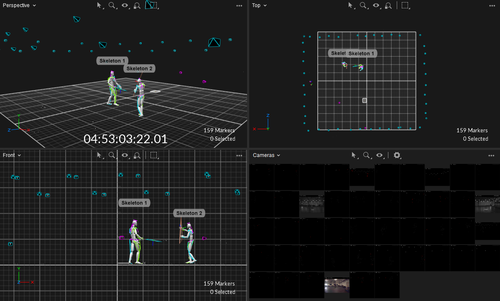
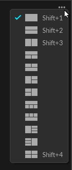
When needed, the Viewport can be split into 3 or 4 smaller views. Click the
 in the top-right corner of the viewport to open the Viewport context menu to select additional panes or different layouts. You can also use the hotkey Shift + 4 to open the four pane layout.
When needed, additional Viewer panes can be opened from the View menu or by clicking the
 icon on the main toolbar.
Viewport Navigation Controls
Most of the navigation controls in Motive are customizable, including mouse and Hotkey controls. The Hotkey Editor Pane and the Mouse Control Pane under the Edit tab allow you to customize mouse navigation and keyboard shortcuts to common operations.
Viewport Mouse Control
Mouse controls in Motive can be customized from the Mouse tab in application settings panel to match your preference. Motive also includes common mouse control presets for Motive (the default), Blade, Maya, MotionBuilder and Visual3D applications. Click the ![]() button to open the Settings panel.
button to open the Settings panel.
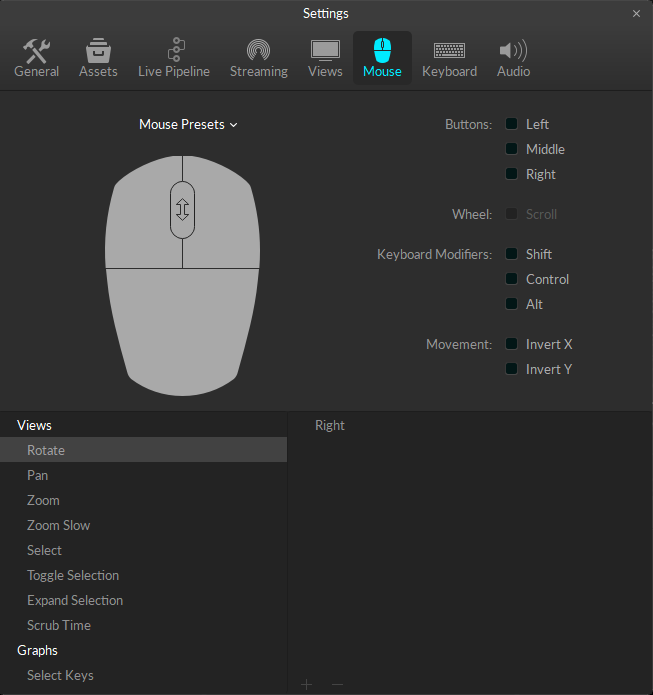
The table below lists basic actions that are commonly used for navigating the viewports in Motive:
Rotate view
Right + Drag
Pan view
Middle (wheel) click + drag
Zoom in/out
Mouse Wheel
Select in View
Left mouse click
Toggle Selection in View
CTRL + left mouse click
Hotkeys
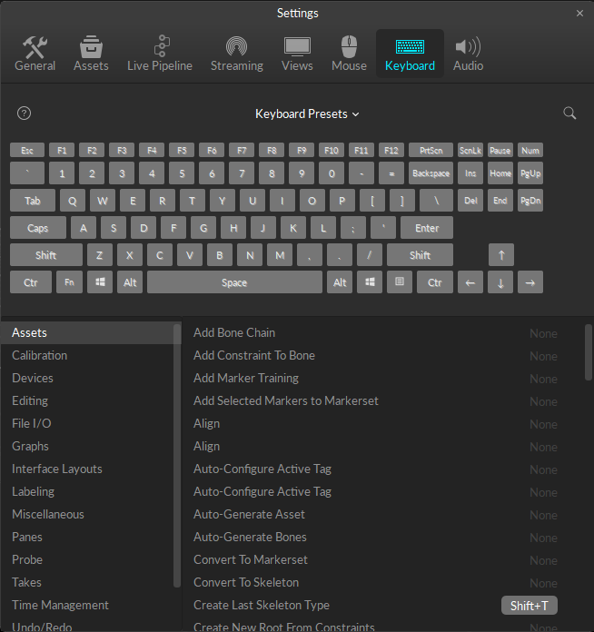
Hotkeys speed up workflows. See all the defaults on the Motive Hotkeys page. To create custom hotkeys, save or import a keyboard preset, click the ![]() button to open the Settings panel.
button to open the Settings panel.
Control Deck
The Control Deck is always docked at the bottom of Motive, providing both recording and navigation controls over Motive's two operating modes: Live and Edit.
The ![]() button at the far left of the Control Deck switches between Live and Edit mode, with the active mode shown in cyan. Hotkey Shift + ~ toggles between Live and Edit modes.
button at the far left of the Control Deck switches between Live and Edit mode, with the active mode shown in cyan. Hotkey Shift + ~ toggles between Live and Edit modes.
When using a timecode generator, you can control where the timecode data is displayed, either in the 3D view (default), in the Control Deck, or not shown at all.
From the Applications Settings panel, select Views -> 3D -> Heads Up Display -> Timecode.
Live Mode
All cameras are active and the system is processing camera data.
If the system is calibrated, Motive live-reconstructs 2D camera data into labeled and unlabeled 3D trajectories (markers) in real-time.
Live tracking data can stream to other applications using the data streaming tools or the NatNet SDK.
The system is ready for recording. Capture controls are available in the Control Deck.

Edit Mode
Used for processing a loaded Take file (pre-recorded data). Cameras are not active.
Playback controls are available in the Control Deck, including a timeline (in green) at the top of the control deck for scrubbing through the recorded frames.

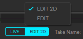
Edit Mode When needed, you can switch from editing in 3D to 2D mode, to view the real-time unreconstructed 3D data. Use this to perform a post-processing reconstruction pipeline to re-obtain a new set of 3D data.
Graph View pane
The Graph View pane is used to plot live or recorded channel data. There are many uses cases for plotting data in Motive; examples include tracking 3D coordinates of the reconstructed markers, 3D positions and orientations of Rigid Body assets, force plate data, analog data from data acquisition devices, and many more.
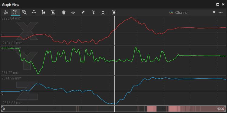
You can switch between existing layouts or create a custom layout for plotting specific channel data.
Basic navigation controls are highlighted below. For more information on graphing data in Motive, please read the Graph View pane page.
Graph View Navigation Controls
Navigate Frames (Alt + Left-click + Drag )
Hold the Alt key while left-clicking and dragging the mouse left or right over the graph to navigate through the recorded frames. You can use the mouse scroll also.
Pan (Scroll-click + Drag)
Scroll-click and drag to pan the view vertically and horizontally throughout plotted graphs. Dragging the cursor left and right pans the view along the horizontal axis for all of the graphs. When navigating vertically, scroll-click on a graph and drag up and down to also pan vertically.
Zoom (Right-click + Drag)
Right-click and drag on a graph to zoom in and out on both vertical and horizontal axis. If Autoscale Graph ![]() is enabled, the vertical axis range will be fixed according to the max and min values of the plotted data.
is enabled, the vertical axis range will be fixed according to the max and min values of the plotted data.
Other Ways to Zoom:
Press Shift + F to zoom out to the entire frame range.
Zoom to a frame range by Alt + right-clicking the graph and selecting the specific frame range to zoom to.
When a frame range is selected in the timeline, press F to quickly zoom to it.
Select Frame Range (Left-click + Drag)
Frame range selection is used when making post-processing edits on specific ranges of the recorded frames. Select a specific range by left-clicking and dragging the mouse left and right, and the selected frame ranges will be highlighted in yellow. You can also select more than one frame ranges by holding the shift key while selecting multiple ranges.
Graph View Navigation Bar
The Navigation Bar at the bottom of the Graph View pane can also be used to

Navigate Frames (Left-click)
Left-click and drag on the navigation bar to scrub through the recorded frames. You can use the mouse scroll also.
Pan View Range
Scroll-click and drag to pan the view range.
Frame Range Zoom
Zoom to a frame range by re-sizing the scope range using the navigation bar handles. As noted above, you can also do this by pressing Alt + right-clicking on the graph to select the range to zoom to.
Working Range / Playback range
The working range (also called the playback range) is both the view range and the playback range of a corresponding Take in Edit mode. In playback, only the working range will play, and in the Graph View pane, only the data for the working range will display.
Tip: Use the working range to limit exported tracking data to a specific range.
The working range can be set from different places:
In the navigation bar of the Graph View pane, drag the handles on the scrubber.
Use the navigation controls on the Graph View pane to zoom in or zoom out on the desired range.
Enter the start and end frames of the working range in the
 fields in the Control Deck.
Selection Range
The selection range is used to apply post-processing edits only to a specific frame range of a Take. The selected frame range is highlighted in yellow on both Graph View pane and the Control Deck Timeline.
Gap Indication
When playing back a recorded capture, red marks on the navigation bar indicate areas with occlusions of labeled markers. Brighter colors indicate a greater number of markers with labeling gaps.
Application Settings
Motive's Application Settings panel holds application-wide settings, including:
Startup configuration and display options for both 2D and 3D viewports.
Settings for asset creation.
Live-pipeline parameters for the Solver and the 2D Filter settings for the cameras.
The Cameras tab includes the 2D filter settings that determine which reflections are classified as marker reflections on the camera views.
The Solver settings determine which 3D markers are reconstructed in the scene from the group of marker reflections from all the cameras.
Access Application Settings from the Edit menu or by clicking the ![]() icon on the main toolbar. Read more about all of the available settings on the Application Settings pages.
icon on the main toolbar. Read more about all of the available settings on the Application Settings pages.
To reset all application settings to Motive defaults, select Reset Application Settings from the Edit menu.
Live Pipeline > Solver Settings
The Solver tab on the Live Pipeline settings panel configures the real-time solver engine. These are some of the most important settings in Motive as they determine how 3D coordinates are acquired from the captured 2D camera images and how they are used for tracking Rigid Bodies and Skeletons. Understanding these settings is very important for optimizing the system for the best tracking results.
Live Pipeline > Camera Settings
Under the Camera tab, you can configure the 2D Camera filter settings (circularity filter and size filter) as well as other display options for the cameras. The 2D Camera filter setting is a key setting for optimizing the capture.
For most applications, the default settings work well, but it is still helpful to understand these core settings for more efficient control over the camera system.
For more information, read through the Application Settings: Live Pipeline page and the Reconstruction and 2D Mode.
Layouts
Predefined Layouts
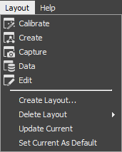
Motive includes several predefined layouts suited to various workflow activities. Access them from the Layout menu, or use the buttons in the top right corner of the screen.

Customized Layouts
The User Interface (UI) layout in Motive is highly customizable.
Select the desired panes from the View menu or from the standard toolbar.
All panes can be undocked to float, dock elsewhere, or stack with other panes with a simple drag-and-drop.
Reposition panes using on-screen docking guides:

Drag-and-drop the pane over the icon for the desired position. To have the pane float, drop it away from the docking guides.
Stacked panes form a tabbed window. The option to stack is only available when dragging a pane over another stackable pane.
Custom layouts can be saved and loaded again, allowing a user to easily switch between default and custom configurations suitable for different needs.
Select Create Layout... from the Layout menu to save your custom layout.
The custom layout will appear in the selection list to the left of the Layout buttons.
Custom layouts can also be accessed using HotKeys, with Ctrl+6 through Ctrl+9 set for user layouts by default.
Note: Layout configurations from Motive versions older than 2.0 cannot be loaded in latest versions of Motive. Please re-create and update the layouts for use.
Was this helpful?

