White/Blacklisting Cameras
Overview
This page provides instructions on how to configure the CameraNicFilter.xml file to whitelist or blacklist specific cameras from the connected camera network.
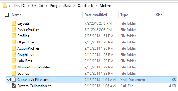
Starting with Motive 2.1, you can specify which cameras to utilize among the connected Ethernet cameras in a system. This can be done by setting up an XML file (CameraNicFilter.xml) and placing it in Motive's ProgramData directory: C:\ProgramData\OptiTrack\Motive\CameraNicFilter.xml. Once this is set, Motive will initialize only the specified cameras within the respective network interface. This allows users to distribute the cameras to specific network interfaces on a computer or on multiple computers.
Additional Note:
This filter works with Ethernet camera systems only. USB camera systems are not supported.
At the time of writing, the eSync is NOT supported. In other words, the eSync cannot be present in the system in order for the filter to work properly.
Applications
For common applications, there is usually no need to separate the cameras to different network interfaces. However, there are few situations where you may want to use this filter to segregate the cameras. Below are some of the sample applications of the filters:
Multiple Prime Color cameras
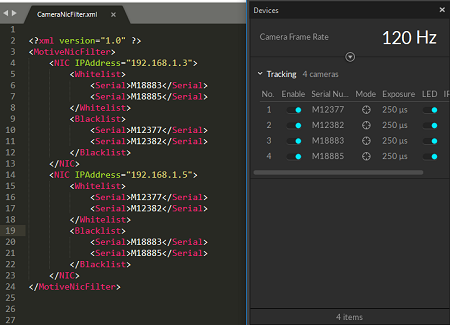
When there are multiple Prime Color cameras in a setup, you can configure the filter to spread out the data load. In other words, you can uplink color camera data through a separate network interface (NIC) and distribute the data traffic to prevent any bandwidth bottleneck. To accomplish this, multiple NICs must be present on the host computer, and you can distribute the data and uplink them onto different interfaces.
Active marker tracking on multiple capture volumes
For active marker tracking, this filter can be used to distribute the cameras to different host computers. By doing so, you can segregate the cameras into multiple capture volumes and have them share the same connected BaseStation. This could be beneficial for VR applications especially if you plan on having multiple volumes to calibrate because you can use the same active components between different volumes.
Configuring the XML File
To separate the cameras, you will need to use a text editor to create an XML file named CameraNicfilter.xml. In this XML file, you will specify which cameras to whitelist or blacklist within the connected network interface. Please note that it is very important for the XML file to match the expected format; for this reason, we strongly recommend to first copy-and-paste the template and start from there.
Attached below is a basic template of the CameraNicFilter.xml file. On each NIC element, you can specify each network interface using the IPAddress attribute, and then in its child elements, you can specifically set which cameras to whitelist or blacklist using their serial numbers.
Sample XML File
Network Interface
<NIC>
For each network interface that you will be using to communicate with the cameras, you will need to create a <NIC> element and assign a network IP address (IPv4) to its IPAddress attribute. Then, under each NIC element, you can specify which cameras to use or not to use.
IP Address
Please make sure correct IP addresses are assigned when configuring the NIC element. Run the ipconfig command on the windows command prompt to list out the assigned IP addresses of the available networks on the computer and then use the IPv4 address of the network that you wish to use. When necessary, you can also set a static IP address for the network interface and use a known address value for easier setup.
Cameras
<Whitelist> / <Blacklist>
Under the NIC element, define two child elements: <Whitelist> and <Blacklist>. In each element, you will be specifying the cameras using their serial numbers. Within each network interface, only the cameras listed under the <Whitelist> element will be used and all of the cameras under <Blacklist> will be ignored.
<Serial>
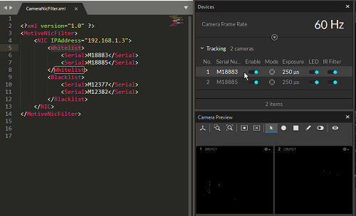
As shown in the above template, you can specify which cameras to whitelist or blacklist using the corresponding camera serial numbers. For example, you can use the following to specify the camera (M18883) <Serial>M18883</Serial>. You can also use a partial serial number as a wildcard to specify all cameras with the matching serial number. For example, if you wish to blacklist all Color cameras in a network (192.168.1.3), you can use C as the wildcard serial number since the serial number of all color cameras start with C.
Save the XML File
Once the XMl file is configured, please save the file in the ProgramData directory: C:\ProgramData\OptiTrack\Motive\CameraNicFilter.xml. If everything is set up properly, only the whitelisted cameras under each network interface will get initialized in Motive, and the data from only the specified cameras will be uplinked through the respective network interface.

Samples


Was this helpful?

