> For the complete documentation index, see [llms.txt](https://docs.optitrack.com/llms.txt). Markdown versions of documentation pages are available by appending `.md` to page URLs; this page is available as [Markdown](https://docs.optitrack.com/motive/calibration/calibration-squares.md).

# Calibration Squares

During the [Calibration](/motive/calibration.md) process, a calibration square is used to define the global coordinate axes as well as the ground plane for the capture volume. This page covers the various calibration squares available.&#x20;

Each calibration square has a different [vertical offset](#vertical-offset) value. When defining the ground plane, Motive will recognize the square and adjust the offset accordingly.

## Square Types

<details>

<summary>ActiveIO Square</summary>

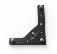
Using ActiveIO technology, this square is used to define the ground plane in systems with SlimX or VersaX cameras, or for very large volumes.&#x20;

&#x20;Long arm: Positive z

* Short arm: Positive x
* Vertical offset: 45.2 mm
* Markers: Active &#x20;
<figure><img src="/files/19I09g9WN8kRodYPPfFx" alt="" width="563"><figcaption></figcaption></figure>

</details>

<details>

<summary>CS-100</summary>

Used to define a ground plane in a small, precise motion capture volumes.

* Long arm: Positive z
* Short arm: Positive x
* Vertical offset: 11.5 mm
* Marker size: 9.5 mm (diameter)

<figure><img src="/files/d93WVoAjQ3P0QykDAbxa" alt=""><figcaption></figcaption></figure>

</details>

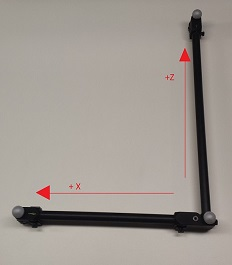
<details>

<summary>CS-200</summary>

* Long arm: Positive z
* Short arm: Positive x
* Vertical offset: 19 mm
* Marker size: 14 mm (diameter)

<figure><img src="/files/JejlPooHreP7ISvCEGPd" alt=""><figcaption></figcaption></figure>

</details>

<details>

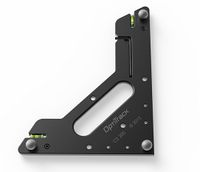
<summary>CS-400</summary>

Used for general for common mocap applications. Contains knobs for adjusting the balance as well as slots for aligning with a force plate.

* Long arm: Positive z
* Short arm: Positive x
* Vertical offset: 45 mm
* Marker size: 19 mm (diameter)

<figure><img src="/files/1qxIPspRVtUJsdzuA2DQ" alt=""><figcaption></figcaption></figure>

</details>

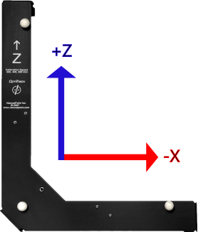
<details>

<summary>Legacy L-Frame Square</summary>

Legacy calibration square designed before changing to the Right-hand coordinate system.

* Long arm: Positive z
* Short arm: Negative x

<figure><img src="/files/dNL5Lb9aXDydmqWDtkad" alt=""><figcaption></figcaption></figure>

</details>

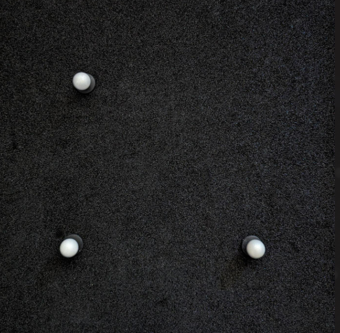
<details>

<summary>Custom Calibration Square</summary>

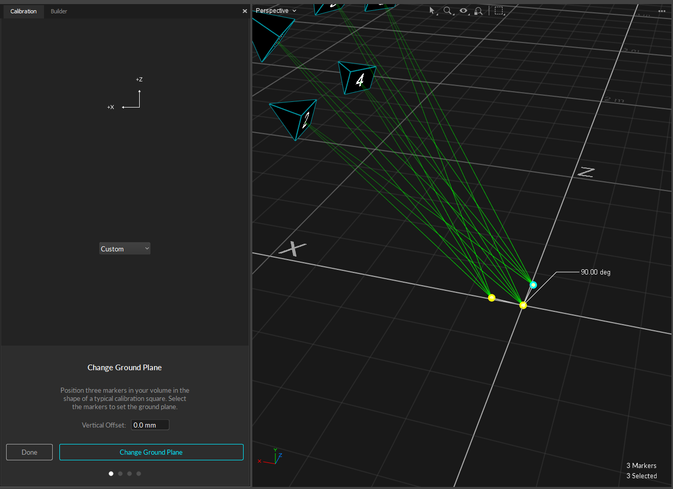
Position three markers in your volume in the shape of a typical calibration square (creating a \~90 degree angle with one arm longer than the other). Then select the markers to set the ground plane.

* Long arm: Positive z
* Short arm: Negative x

<figure><img src="/files/nS96CmaJdhFEi1kt2HdG" alt="" width="563"><figcaption></figcaption></figure>

</details>

{% hint style="info" %}
When creating a custom ground plane, you can use Motive to help you move the markers to create approximately 90 degree between the 3 markers. This is of course contingent on how good your calibration is, however, this will still give you a fairly accurate starting point when setting your ground plane.&#x20;
{% endhint %}

<figure><img src="/files/syO9VSLZsnHcFjnHZAWF" alt=""><figcaption></figcaption></figure>

## Vertical Offset

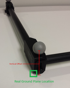
The Vertical Offset is the distance between the center of the markers on the [calibration square](/motive/calibration/calibration-squares.md) and the actual ground and is a required value in setting the global origin.&#x20;

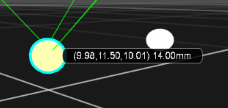
Motive accounts for the vertical offset when using a standard OptiTrack calibration square, setting the origin at the bottom corner of the calibration square rather than the center of the marker.&#x20;

<div><figure><img src="/files/yuP681J0CHUrqRvriTU3" alt=""><figcaption><p>Vertical offset of the CS-400 calibration square.</p></figcaption></figure> <figure><img src="/files/dHKasG2KhU5TENam59ss" alt=""><figcaption><p>Ground plane marker is offset from the global origin after calibration.</p></figcaption></figure></div>

When using a custom calibration square, measure the distance between the center of the marker and the lowest tip at the vertex of the calibration square. Enter this value in the *Vertical Offset* field in the Calibration pane.&#x20;

{% hint style="info" %}
The **Vertical Offset** property can also be used to place the ground plane at a specific elevation. A positive offset value will set the plane below the markers, and a negative value will set the plane above the markers.
{% endhint %}

## Coordinate System&#x20;

The Right-Handed Coordinate System is used as the standard, across internal and exported formats and data streams.&#x20;


---

# Agent Instructions
This documentation is published with GitBook. GitBook is the documentation platform designed so that both humans and AI agents can read, navigate, and reason over technical content effectively. Learn more at gitbook.com.

## Querying This Documentation
If you need additional information that is not directly available in this page, you can query the documentation dynamically by asking a question.

Perform an HTTP GET request on the current page URL with the `ask` query parameter, and the optional `goal` query parameter:

```
GET https://docs.optitrack.com/motive/calibration/calibration-squares.md?ask=<question>&goal=<endgoal>
```

`ask` is the immediate question: it should be specific, self-contained, and written in natural language.
`goal` is optional and describes the broader end goal you are ultimately trying to accomplish on behalf of the user. GitBook uses it to tailor the answer towards what is most useful for that goal.

The response will contain a direct answer to the question and relevant excerpts and sources from the documentation.

Use this mechanism when the answer is not explicitly present in the current page, you need clarification or additional context, or you want to retrieve related documentation sections.