Multiple Device Setup

Overview

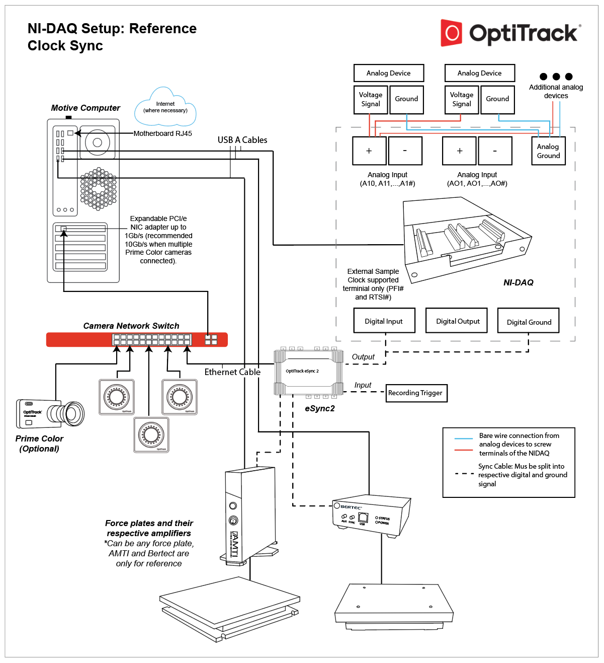
This page demonstrates a sample system setup involving multiple external devices. Specifically, one National Instruments Data Acquisition (NI-DAQ) device, two force plates, and a recording trigger will be integrated. Only basic step-by-step instructions will be covered in this guide. For detailed explanation of each device integrations, visit the following pages:

Requirements

  • Motive

  • Motive: the Peripheral Device module and the NI-DAQmx plugin (15.1.1 or later).

  • Ethernet camera system with the eSync synchronization hub.

  • USB NI-DAQ: Supported Devices with external sample clock support.

  • Force Plate System: Bertec or AMTI

  • Record Trigger device (external device)

Sync Chain Setup Steps

For general instructions on setting up the mocap system, refer to the Hardware Setup pages. This guide assumesthe camera system and the eSync 2 have been already installed.

Step 1. [Hardware Setup]

First of all, connect the external devices to the appropriate input or output ports of the eSync 2.

  • NI-DAQ (child): Connect one of the Output ports of the eSync 2 to an input terminal of the USB NI-DAQ device. The input terminal must support external sample clock signals in order to sync with the clock signal from the eSync 2. When integrating bare wire DAQ devices, respective ground signals must be separated from the BNC port. Sync Signal: Internal Clock

  • Force Plates (child): Connect the Output ports of the eSync 2 to a sync input port on the force plate amplifier. Sync Signal: Recording Pulse (AMTI) / Recording Gate (Bertec) for triggered sync. External clock sync cannot be used in this setup, because the clock signal will be used mainly for synchronizing the NI-DAQ device which usually runs at a faster sampling rate.

  • Recording Trigger (trigger): Using sync cables, connect the trigger device into one of the Input ports of the eSync 2.

Bertec AM6800: For Bertec systems using the AM6800 amplifier, the eSync's output port connects to the ANALOG OUTPUT port of the amplifier. The female 15-pin D-Sub connector included with the Bertec system must be used to separate the ZERO and SYNC cables. The ZERO cable connects to the eSync's output port, and the SYNC cable connects between force plate amplifiers. See: Bertec Hardware Setup

Step 2. [Hardware Setup] Connect the devices.

Connect the USB cables from the force plates and the NI-DAQ device to the host PC.

Step 3. [Software Setup] Install Peripheral Device module and NI-DAQmx driver
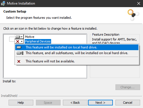
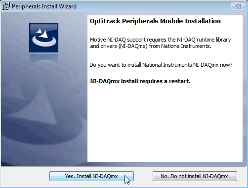
For integrating force plates and NI-DAQ devices, the Peripheral Device module and the NI-DAQmx driver must be installed along with Motive; both of which can be installed during the Motive installation process.

Step 4. [Motive] Launch Motive.

If the devices are properly recognized, they will be listed under the Devices pane in Motive.

Step 5. Place CS-400 on force plate
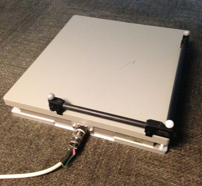
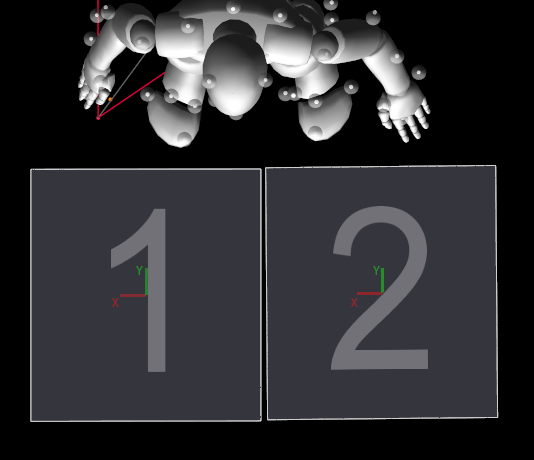
Place the calibration wand on the force plate so that vertex of the wand is located at the right-hand corner of the side where the cable input is located (as shown in the image below). A correct placement of the calibration square is important because it determines the orientation of the force plate and its local coordinate axis within the global system. The coordinate systems for force plates are independent of the system used Motive.

Step 6. [Motive] Zero the devices.

Right-click on the NI-DAQ device or the force plates either on the Devices pane or on the Perspective View and click Zero. This will tare the devices and set the currently detected voltage/force to zero.

Step 7. [Motive → Properties: eSync]

Now, let's configure the synchronization setup. This is done through configuring the properties of the eSync. Open the Devices pane and the Properties pane. Select the eSync under the list of devices and its properties will be listed out in the Properties pane. Here, you can adjust the properties to change the sync source, sync input/output behaviors.

Step 8. [Motive → Properties: eSync] Select the Sync Source.

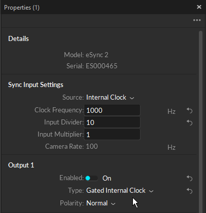
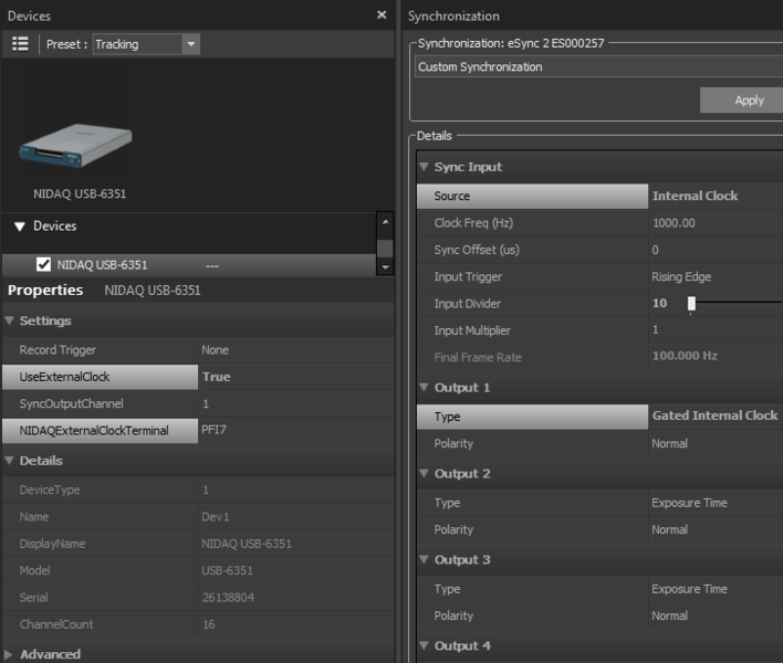
First of all, you need to select and configure the sync input source. In this setup, the Internal Clock signal of the eSync will be used to synchronize the camera system. Set the Sync Input: Source to Internal Clock.

Step 9. [Motive → Properties: eSync] Configure the Sync Source.
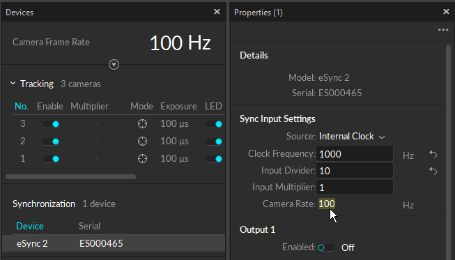
Once the Internal Clock is selected as the sync source, configure the clock signal:

  • Clock Freq (Hz): This sets the frequency of the clock signal. In this setup, the clock signal will be used to sync the camera system frame rate and also the acquisition rate of the NI-DAQ devices. Since the NI-DAQ devices usually sample at a higher frame rate, first set the clock frequency to the desired NI-DAQ sampling rate and apply input divider and multiplier for the camera system.

  • Input Trigger/Divider/Multiplier: Adjust the input divider and multiplier to derive the camera system frame rate from the configured internal clock signal. The final frame rate will be displayed at the bottom of the Sync Input section. Only the supported camera frame rate can be applied.

Step 10. [Motive → Properties: eSync 2] Configure the Sync Outputs.

Now, configure the output signal into the child devices. Configure the corresponding output port that each device is connected.

  • NI-DAQ: Set the output type of the connected output port to Gated Internal Clock signal. This will set the eSync 2 so that the internal clock is sent out when Motive starts recording.

  • Force Plates: Set the output type of the connected output port to Recording Gate (Bertec) or Recording Pulse (AMTI). The force plate systems will synchronize with the recording trigger from the eSync 2.

AMTI Force plates can also be synchronized through Gater Internal Clock signal. See AMTI Force Plate Setup page for more information.

Step 11. [Motive: → Properties: eSync]] Configure the Remote Trigger device.

Now let's configure the Record Trigger device. Under the Record Triggering section, set the trigger source to the input port that the device is connected to, and select appropriate trigger edge depending on the morphology of the trigger signal.

Step 12. [Motive: → Properties: eSync]] Apply the configuration.

Now that the eSync properties have been configured, the sync chain of the connected devices should be set up. Next step is to configure the properties of the external devices.

Step 13. [Motive → Properties: NI-DAQ] Configure NI-DAQ properties in Motive

Click on the NI-DAQ device under the Devices pane and open the Properties pane to configure its sync properties. The following configuration sets the NI-DAQ devices to synchronize its data acquisition with the clock signal from the eSync.

  • Use External Clock: True.

  • NIDAQExternalClockTerminal: Designate input channel of the NI-DAQ.

  • SyncMode: Free Run.

Step 14. [Motive → Properties: Force Plate]

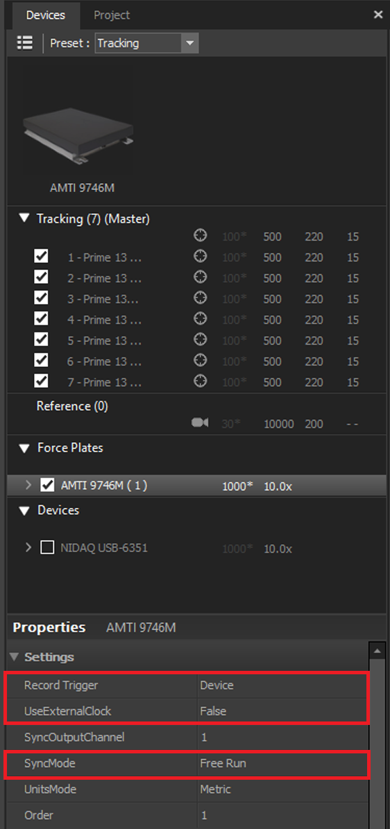
Click on the Force Plate device under the Devices pane and open the Properties pane to configure its sync properties. The following configuration sets the force plates to trigger sync to the recording signal from the eSync 2:

  • Record Trigger: Device

  • Use External Clock: False

  • Sync Mode: Free Run

Step 15. [Motive]

Now the systems are synchronized. When you start recording in Motive, precisely aligned data will be collected.

Step 16. [Motive] Recording Trigger.

To utilize the external recording trigger device, press the record button in Motive and set it to a standby mode. Then use the device to send the recording trigger to the eSync 2, which will either initiate or stop recording each time a trigger is received.