LogoLogo
WebsiteSupportDownloadsForumsQuick LinksContact Us
v3.2
v3.2
  • OptiTrack Documentation
  • WHAT'S NEW
    • What's New in Motive 3.2
  • QUICK START GUIDES
    • Quick Start Guide: Getting Started
    • Quick Start Guide: Prime Color Camera Setup
    • Quick Start Guide: Precision Capture
    • Quick Start Guide: Tutorial Videos
    • Quick Start Guide: Active Marker Tracking
    • Quick Start Guide: Outdoor Tracking Setup
  • HARDWARE
    • Cameras
      • Ethernet Cameras
        • PrimeX 120
        • PrimeX 41
        • PrimeX 22
        • PrimeX 13
        • PrimeX 13W
        • SlimX 13
        • Prime Color
        • VersaX 22
        • VersaX 41
        • VersaX 120
      • USB Cameras
        • Slim 3U
        • Flex 13
        • Flex 3
        • V120:Duo
        • V120:Trio
        • Adjusting Global Origin for Tracking Bars
    • Prepare Setup Area
    • Camera Mount Structures
    • Camera Placement
    • Ethernet Camera Network Setup
      • General Overview and Specs
      • Windows 10 Network Settings
      • Cabling and Load Balancing
      • Switch Configuration for PrimeX 120
      • NETGEAR ProSafe GSM7228S: Disabling the Broadcast Storm Control
      • White/Blacklisting Cameras
    • USB Camera System Setup
      • USB Camera Network Overview and Specs
      • V120:Duo and Trio Setup
      • Tracking Bar Coordinate System
        • Transforming Coordinate System: Global to Local
    • Aiming and Focusing
    • Camera Status Indicators
  • MOTIVE
    • Installation and License Activation
    • Motive Basics
    • Calibration
      • .mcal XML Calibration Files
      • Continuous Calibration
      • Continuous Calibration (Info Pane)
      • Calibration Squares
    • Markers
    • Assets
      • Gizmo Tool: Translate, Rotate, and Scale
    • Rigid Body Tracking
      • Aligning Rigid Body Pivot Point with a Replicated 3D Model
    • Skeleton Tracking
    • Trained Markersets
    • IMU Sensor Fusion
    • Data Recording
      • Data Types
    • Labeling
    • Data Editing
    • Data Export
      • Data Export: BVH
      • Data Export: C3D
      • Data Export: CSV
      • Data Export: FBX
      • Data Export: TRC
    • Data Streaming
    • Camera Video Types
    • Audio Recording
    • Motive HotKeys
    • Measurement Probe Kit Guide
    • Motive Batch Processor
    • Reconstruction and 2D Mode
  • MOTIVE UI PANES
    • Settings
      • Settings: General
      • Settings: Assets
      • Settings: Live Pipeline
      • Settings: Streaming
      • Settings: Views
      • Settings: Mouse and Keyboard
      • Settings: Audio
    • Assets Pane
    • Builder Pane
    • Constraints Pane
      • Constraints XML Files
    • Calibration Pane
    • Data Pane
    • Devices Pane
    • Edit Tools Pane
    • Graph View Pane
    • Info Pane
    • Labels Pane
    • Log Pane
    • Probe Pane
    • Properties Pane
      • Properties Pane: Camera
      • Properties Pane: Force Plates
      • Properties Pane: NI-DAQ
      • Properties Pane: OptiHub2
      • Properties Pane: Rigid Body
      • Properties Pane: Skeleton
      • Properties Pane: Take
      • Properties Pane: Trained Markerset
      • Properties Pane: eSync2
    • Status Panel
    • Toolbar/Command Bar
    • Control Deck
    • Viewport
  • PLUGINS
    • OptiTrack Blender Plugin
      • OptiTrack Blender Plugin
    • OptiTrack Unreal Engine Plugin
      • Unreal Engine: OptiTrack Live Link Plugin
        • Quick Start Guide: Real-Time Retargeting in Unreal Engine with Live Link Content
        • Unreal Editor for Fortnite (UEFN): OptiTrack Plugin for Live Link Hub
        • Unreal Engine: Live Link Camera Stream Setup
        • Live Link Content: Active Puck Static Meshes
      • Unreal Engine: MotionBuilder Workflow
      • Unreal Engine: HMD Setup
      • Unreal Engine VCS Inputs
    • OptiTrack Unity Plugin
      • Unity: HMD Setup
    • OptiTrack OpenVR Driver
    • OptiTrack MATLAB Plugin
    • Autodesk Maya
      • Autodesk Maya: OptiTrack Insight VCS Plugin
    • Autodesk MotionBuilder
      • Autodesk MotionBuilder Plugin
      • Autodesk MotionBuilder: OptiTrack Skeleton Plugin
      • Autodesk MotionBuilder: OptiTrack Optical Plugin
      • Autodesk MotionBuilder: OptiTrack Insight VCS Plugin
      • Autodesk MotionBuilder: Timecode Data
    • OptiTrack Peripheral API
    • External Plugins
      • Houdini 19 Integration
  • ACTIVE COMPONENTS
    • Active Components Hardware
      • Active Puck
      • Wired AnchorPuck
      • CinePuck
      • Wired CinePuck
      • BaseStation
      • Information for Assembling the Active Tags
      • Manus Glove Setup
    • Configuration
      • Active Batch Programmer
      • Active Hardware Configuration: PuTTY
      • Active Component Firmware Compatibility
    • Active Marker Tracking
      • Active Finger Marker Set
  • SYNCHRONIZATION
    • Synchronization Hardware
      • External Device Sync Guide: eSync 2
      • External Device Sync Guide: OptiHub2
    • Synchronization Setup
    • OptiTrack Timecode
  • VIRTUAL PRODUCTION
    • Unreal Engine: OptiTrack InCamera VFX
    • Entertainment Marker Sets
    • PrimeX 41
  • MOVEMENT SCIENCES
    • Movement Sciences Hardware
      • General Motive Force Plate Setup
      • AMTI Force Plate Setup
      • Bertec Force Plate Setup
      • Kistler Force Plate Setup
      • Delsys EMG Setup
      • NI-DAQ Setup
      • Multiple Device Setup
    • Movement Sciences Marker Sets
      • Biomechanics Marker Sets
      • Biomech (57)
      • Rizzoli Marker Sets
    • For Visual3D Users
    • Prime Color Camera Setup
      • Prime Color Setup: Required Components
      • Prime Color Setup: Hardware Setup
      • Prime Color Camera Setup: Camera Settings
      • Prime Color Camera Setup: Prime Color FS Calibration
      • Prime Color Setup: Data Recording / Export
      • Prime Color Camera Setup: FAQ / Troubleshooting
      • Prime Color Camera Setup: Windows Network Settings
  • VIRTUAL REALITY
    • VR Plugins
      • VR Unreal Engine
        • OptiTrack Unreal Engine Plugin
        • Unreal Engine: OptiTrack Live Link Plugin
          • UE5.1 Live Link Retarget External Workaround
        • Unreal Engine VCS Inputs
      • VR Unity
        • OptiTrack Unity Plugin
      • VR OpenVR
        • OptiTrack OpenVR Driver
    • VR HMD Setup
      • Unreal Engine: HMD Setup
      • Unity: HMD Setup
      • Manually Calibrating the HMD Pivot Point
      • Sync Configuration with an HTC Vive System
    • SlimX 13
    • Active Marker Tracking
      • Active Finger Marker Set
    • Synchronization Hardware
      • External Device Sync Guide: eSync 2
      • External Device Sync Guide: OptiHub2
  • ANIMATION
    • Autodesk Maya
      • Autodesk Maya: OptiTrack Insight VCS Plugin
    • Autodesk MotionBuilder
      • Autodesk MotionBuilder Plugin
      • Autodesk MotionBuilder: OptiTrack Skeleton Plugin
      • Autodesk MotionBuilder: OptiTrack Optical Plugin
      • Autodesk MotionBuilder: OptiTrack Insight VCS Plugin
      • Autodesk MotionBuilder: Timecode Data
  • ROBOTICS
    • MoCap4ROS2 Setup
    • OptiTrack Robot Applications
    • Outdoor Tracking Setup
  • DEVELOPER TOOLS
    • Developer Tools Overview
    • Camera SDK
      • Class: cCameraModule
      • Class: cUID
    • Motive API
      • Motive API: Quick Start Guide
      • Motive API Overview
      • Motive API: Function Reference
      • Motive API Camera Calibration
    • NatNet SDK
      • NatNet 4.1
      • NatNet: Class/Function Reference
      • NatNet: Creating a Managed (C sharp) Client Application
      • NatNet: Creating a Native (C++) Client Application
      • NatNet: Data Types
      • NatNet: Matlab Wrapper
      • NatNet: Migration to NatNet 3.0 libraries
      • NatNet: Remote Requests/Commands
      • NatNet: Sample Projects
      • NatNet: Unicast Data Subscription Commands
      • Latency Measurements
    • VRPN Sample
    • Peripheral API: Glove Devices
  • SKELETON MARKER SETS
    • Full Body
      • Baseline (41)
      • Core (50)
      • Biomech (57)
      • Conventional (39)
    • Full Body + Fingers
      • Baseline + Passive Fingers (49)
      • Baseline + Active Fingers (57)
      • Core + Passive Fingers (54)
      • Core + Active Fingers (62)
    • Upper
      • Baseline Upper (25)
      • Conventional Upper (27)
    • Lower
      • Baseline Lower (20)
      • Helen Hayes Lower (19)
      • Conventional Lower (16)
    • Hand and Fingers
      • Left/Right Hand (4) Active
      • Left/Right Hand (10) Active + Passive
      • Active Finger Marker Set
    • Glove Device Setup
      • Manus Glove Setup
      • StretchSense Glove Setup
    • Rizzoli Marker Sets
    • Entertainment Marker Sets
    • Rigid Body Skeleton Marker Set
  • GENERAL TROUBLESHOOTING
    • Licensing Troubleshooting
    • Windows 11 Optimization for Realtime Applications
    • Network Troubleshooting
    • Troubleshooting Q&A
    • Running Motive on High DPI Displays
    • Firewall Settings
Powered by GitBook
On this page
  • Skeleton Properties
  • General Settings
  • Visuals
  • Bones (Advanced Settings)
  • Sensor Fusion
  • Smoothing and Damping
  • Solver (Advanced Settings)

Was this helpful?

Export as PDF
  1. MOTIVE UI PANES
  2. Properties Pane

Properties Pane: Skeleton

An in-depth look at the properties available for skeleton assets.

PreviousProperties Pane: Rigid BodyNextProperties Pane: Take

Last updated 2 months ago

Was this helpful?

This page covers properties specific to skeletons. For general information on using and customizing the Properties pane, see the page. For detailed descriptions of properties for other asset types or devices, please see the following pages:

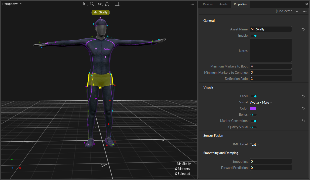
Skeleton properties determine how Skeleton assets are tracked and displayed in Motive. To view related properties, select a Skeleton asset in the or in the 3D viewport, and the corresponding properties will be listed under the . These properties can be modified both in Live and Edit mode. Default creation properties are listed under the .

Advanced Settings

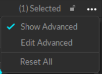
The Properties pane contains advanced settings that are hidden by default. To access these settings, click the button in the top right corner.

Use the Edit Advanced option to customize which settings are in the Advanced Settings category and which appear in the standard view, to show only the settings that are needed specifically for your capture application.
Skeleton Properties

General Settings

The following items are available in the General Properties section. Properties are Standard unless noted otherwise.
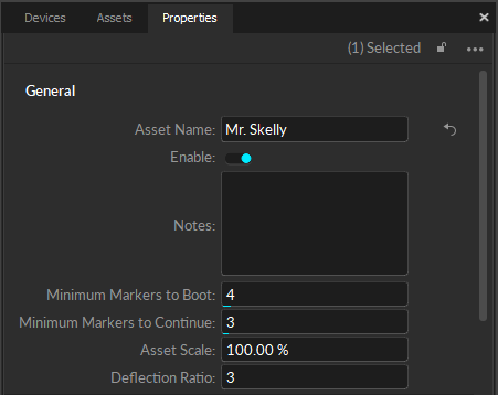
Asset Name

Display the name of selected Skeleton asset in an editable field.

Enable

Enable or Disable tracking of the selected Skeleton. A disabled Skeleton will not be tracked, and its data will not be included in the exported or streamed tracking data or displayed in the 3D Viewport.

  • Select Markers -> Hide for Disabled Assets.

Minimum Markers to Boot

The minimum number of markers that must be tracked and labeled in order for a Skeleton, or each Skeleton bone, to be booted or first tracked.

Minimum Markers to Continue

The minimum number of markers that must be tracked and labeled in order for a Skeleton, or each Skeleton bone, to continue to be tracked after the initial boot.

Asset Scale (Advanced Setting)

Increase or decrease the size of the Skeleton by scaling the asset. By default, the Asset Scale is set to 100%.

Deflection Ratio (Advanced Setting)

Allows the asset to deform more or less to accommodate markers that don't fit the model. High values will allow assets to fit onto markers that don't match the model as well.

Visuals

The following items are available in the Visuals section. Properties are Standard unless noted otherwise.
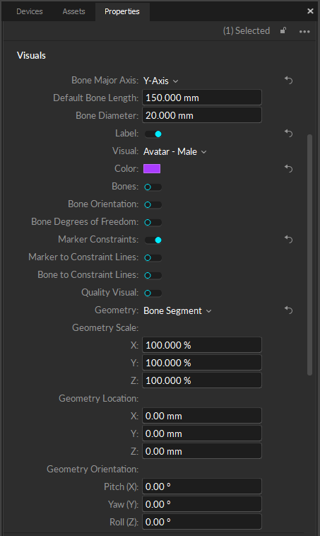
Bone Major Axis (Advanced Setting)

Set the axis with which the skeleton should be aligned. The default value is Y-Axis.

Default Bone Length (Advanced Setting)

Set the offset (in mm) from the bone to the end effector, along the major axis, for bones that do not have child bones.

Bone Diameter (Advanced Setting)

Set the diameter of the bone (in mm).

Label

Visual

Select how the Skeleton will be shown in the 3D perspective view.

  • None: Displays only constraints and marker sticks.

  • Segment: Displays Skeleton as individual Skeleton segments.

  • Avatar (male): Displays Skeleton as a male avatar.

  • Avatar (female): Displays Skeleton as a female avatar.

Color

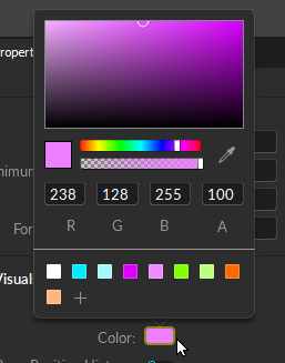
Set the color of the selected Skeleton in the 3D Perspective View. Click the box to bring up the color picker:
Bones

Show or hide Skeleton bones. The bones will display on top of the Visual selection.

Bone Color

This field is available whenever the Bones visual is toggled on and allows you to change the color of the skeleton bones.

Bone Orientation (Advanced Setting)

Displays orientation axes of each segments in the Skeleton.

Bone Degree of Freedom (Advanced Setting)

Display degrees of freedom, position and orientation, for each bone.

Marker Constraints

Show the Marker Constraints as transparent spheres on the Skeleton. Marker Constraints are the expected marker locations according to the skeleton solve.

Marker to Constraint Lines (Advanced Setting)

Show lines between labeled Skeleton markers and corresponding expected marker locations. This helps to visualize the offset distance between actual marker locations and the Marker Constraints.

Bone to Constraint Line (Advanced Setting)

Display a dotted line to connect each Skeleton bone to its respective Marker Constraints.

Quality Visual

When enabled, the color of the Skeleton segments will change whenever there are tracking errors.

  • Red indicates there are no visible markers contributing to the reconstruction in the current frame.

  • Blue indicates a bone has reached its degree of freedom limit.

Geometry (Advanced)

Skeleton assets use the Bone Segment geometry, which is selected by default. To use your own geometric model, select Custom Model. This will open the Attached Geometry field.
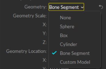
Attach a valid geometric model to the segment to display in the the 3D Viewport. Sphere, box, cylinder, and bone segment shapes are built-in.

Attached Geometry (Advanced)

The Attached Geometry field becomes available whenever Custom Model is selected for the Rigid Body geometry.

Click the folder to the right of the field to browse to the OBJ or FBX file to replace the Skeleton. Properties configured in the corresponding MTL files alongside the OBJ file will be loaded as well.

Geometry Settings (Advanced)

Settings to adjust the scale, location, and orientation (Pitch, Yaw, and Roll) are available.

Bones (Advanced Settings)

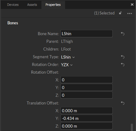
Skeleton templates include pre-defined bones and bone chains that mirror the human body. The Bones properties display data specific to the selected bone. If multiple bones are selected, properties that differ will display Mixed for the value.

To view and update properties for a specific bone, select just that bone in the 3D Viewport.

All properties in the Bones section are Advanced properties.
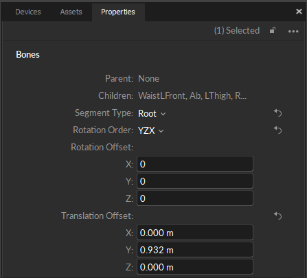
Bone Name

An editable field that shows the name of the selected bone. When more than one bone is selected, the field will display Mixed.

The hip bone is the root of the skeleton and does not display a Bone Name when selected.

It is not recommended to rename Skeleton bones.

Parent

The Parent bone is the first bone in a Bone Chain. This property shows which bone in the Skeleton is the parent of the currently selected bone.

  • When the selected bone is the hip (or root bone), the Parent field will display None.

  • When the selected bone is directly attached to the hip (root bone), this field will display the name of the Asset.

  • When more than one bone is selected and they do not share the same Parent bone, the field will display Mixed.

Children

A Child bone connects to the parent bone in a Bone Chain. This property shows which bone in the Skeleton is the child to the currently selected bone. When the selected bone is the end of the chain, or if there is no bone chain, the Child field will display None.

Segment Type

Identifies the Skeleton bone segment for the selected bone.

Rotation Order

Euler angle rotation order used for calculating the bone hierarchy.

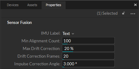
Sensor Fusion

Sensor Fusion properties relate to active devices. They are only applicable to skeletons when using the 6 Rigid Body skeleton template with active devices.

Smoothing and Damping

Smoothing

Apply double exponential smoothing to translation and rotation of the Skeleton. Increasing this setting may help smooth out noise in the Skeleton tracking, but excessive smoothing can introduce latency. The default value is 0 (disabled).

Forward Prediction

Compensate for system latency when tracking the corresponding Skeleton by predicting its movement into the future. For this feature to work best, smoothing needs to be applied as well. Please note that using higher values may impact the tracking stability. The default value is 0 (disabled).

Translation Damping (Advanced)

When needed, you can damp down translational tracking of a Skeleton bone on the selected axis.

Rotation Damping (Advanced)

You can also damp down rotational tracking of a Skeleton.

Rotation Damping Axis (Advanced)

When using Rotation Damping, select whether to apply changes to a selected axis or to all.

Solver (Advanced Settings)

Solver properties allow for the adjustment of normal shrinkage and stretching that can occur normally in the human spine and shoulder.

  • Spine Shrink/Stretch Limit: The maximum amount of stretch (or shrinkage) permitted across all four of the bones that comprise the spine: Abdomen, chest, neck, and head.

  • Shoulder Shrink/Stretch Limit: Widens or narrows the shoulder width by the value specified.
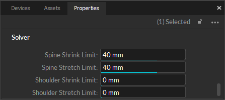
The default values are sufficient for most mocap applications and we recommend NOT changing them. Change these values only if you encounter issues with the solver such as shoulder popping or hand misalignment when an actor is pushing the typical limits, such as hanging by their arms, for example.

Select a skeleton asset in the or in the , and the skeleton's properties will display in the . These properties can be modified both in Live and Edit mode. Default creation properties are listed under the .

To hide the markers associated with a disabled asset in the :

Click to open the Visuals menu.

Display the Skeleton name in the . When selected, a small label will appear over the asset.

For more information on these properties, please see the of the page.

3D Viewport
3D Perspective View
Properties Pane
Properties: Take
Properties: Trained Markerset
Properties: Rigid Body
Properties: Camera
Properties: eSync
Properties: Force Plates
Properties: NI-DAQ
Assets pane
Properties pane
Application Settings
Assets pane
Properties pane
Assets Settings
Properties Pane: Rigid Body
Sensor Fusion section
3D viewport
Properties of the selected Skeleton asset.
Skeleton General Properties
The Visuals Section of the Skeleton Properties pane.
Changing the color of a Skeleton.
Geometry Options for Skeletons.
Attach a Custom Geometry Model.
Skeleton Bones properties for a hip bone. The hip bone is the root of the skeleton.
Skeleton Bone properties for the left shin bone.
Sensor Fusion properties.