Data Export: CSV
Defines the options available when exporting tracking data to a CSV file.
Overview
Captured tracking data can be exported in Comma Separated Values (CSV) format. This file format uses comma delimiters to separate multiple values in each row, which can be imported by spreadsheet software or a programming script. Depending on which data export options are enabled, exported CSV files can contain marker data, and data for Rigid Bodies, Trained Markersets, and/or Skeletons. Data for force plate, NI-DAQs, and other devices will export to separate files if these devices are included in the Take.
For general information on exporting data, please see the Data Export page.
General Export Options
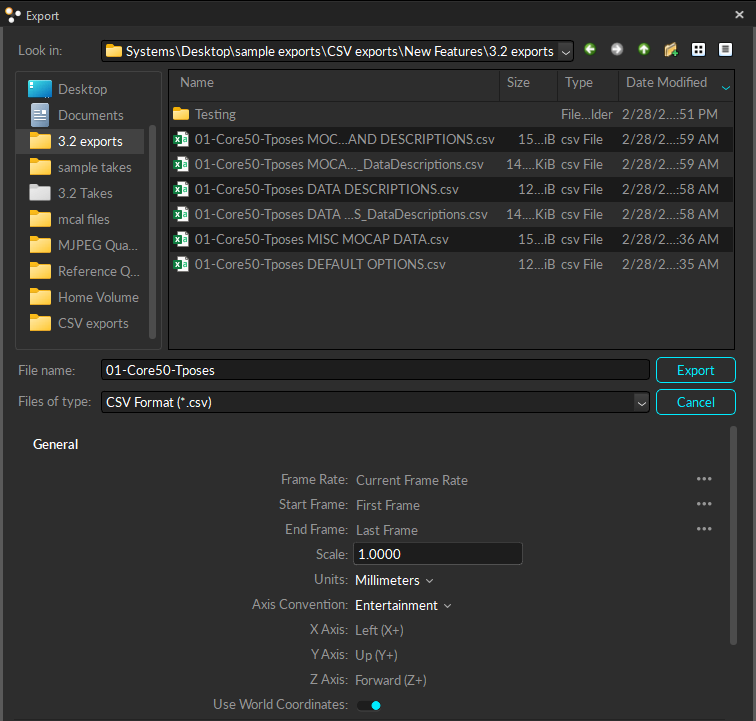
Frame Rate
Number of samples included per second of exported data.
Start Frame
Start frame of the exported data. Set to one of the following:
The recorded first frame of the exported Take (the default option).
The start of the working range (or scope range) as configured under the Control Deck in the Graph View pane.
Custom to enter a specific frame number.
End Frame
End frame of the exported data. Set to one of the following:
The recorded end frame of the exported Take (the default option).
The end of the working range (or scope range) as configured under the Control Deck in the Graph View pane.
Custom to enter a specific frame number.
Scale
Apply scaling to the coordinates/distance of tracked assets in the exported tracking data.
Units
Set the measurement units to use for exported data.
Axis Convention
Sets the axis convention on exported data. This can be set to a custom convention or select preset conventions for Entertainment or Measurement.
X Axis | Y Axis | Z Axis
Allows customization of the axis convention in the exported file by determining which positional data to be included in the corresponding data set.
Use World Coordinates
This option determines whether exported data will be based on world (global) or local coordinate systems.
Coordinate Systems
Coordinates for exported data are either global to the volume or local to the asset.
Global or World Coordinates
Defines the position and orientation in respect to the global coordinate system of the calibrated capture volume. The global coordinate system is the origin of the ground plane, set with a calibration square during the Calibration process.
Local Coordinates
Defines the bone position and orientation in respect to the coordinate system of the parent bone.
Local coordinate axes can be set to visible from Application Settings or in the skeleton properties. The Bone rotation values in the Local coordinate space can be used to roughly represent the joint angles, however, for precise analysis, joint angles should be computed through a biomechanical analysis software using the exported capture data (C3D).
In a skeleton, the hip is always the top-most parent of the segment hierarchy.
Motion Capture Export Options
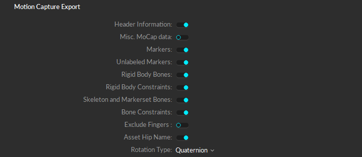
Header information
Detailed information about capture data is included as a header in exported CSV files. See the section CSV Header for specifics.
Misc. MoCap Data
Includes a fourth column of data for each bone or marker tracked.
Mean Error Data is included for each bone.
Size is included for each marker.
Markers
X/Y/Z reconstructed 3D positions for each marker in exported CSV files.
Unlabeled Markers
Includes tracking data of all of the unlabeled makers to the exported CSV file along with other labeled markers. To view only the labeled marker data, turn off this export setting.
Rigid Body Bones
The exported CSV file will contain 6 Degrees of Freedom (6 DoF) data for each rigid body from the Take. This includes orientations (pitch, roll, and yaw) in the chosen rotation type as well as 3D positions (x,y,z) of the rigid body center.
Rigid Body Constraints
3D position data for the location of each Marker Constraint of rigid body assets. This is distinct from the actual marker location. Compared to the positions of the raw marker positions included within the Markers columns, the Rigid Body Constraints show the solved positions of the markers as affected by the rigid body tracking but not affected by occlusions.
Skeleton and Markerset Bones
The exported CSV files will include 6 DoF data for each bone segment of skeletons and trained markersets in exported Takes. 6 DoF data contain orientations in the selected rotation type, and also 3D positions (x,y,z,) for the center of the bone. All skeleton and markerset assets must be solved to export this data.
Bone Constraints
3D position data for the location of each Marker Constraint of bone segments in skeleton and trained markerset assets. Compared to the real marker positions included within the Markers columns, the Bone Markers show the solved positions of the markers as affected by the skeleton tracking but not affected by occlusions.
Exclude Fingers
Exported skeletons will not include the fingers, if they are tracked in the Take file.
Asset Hip Name
When selected, the hip bone data is labeled as Asset_Name:Asset_Name (e.g., Skeleton:Skeleton). When unselected, the exported data will use the classic Motive naming convention of Asset_Name:Hip (e.g., Skeleton:Hip).
Rotation Type
Rotation type determines whether Quaternion or Euler Angles are used for orientation convention in exported CSV files. For Euler rotation, right-handed coordinate system is used and all different orders (XYZ, XZY, YXZ, YZX, ZXY, ZYX) of elemental rotation are available. More specifically, the XYZ order indicates pitch is degree about the X axis, yaw is degree about the Y axis, and roll is degree about the Z axis.
Other Exports
You can export additional data to separate .csv files along with the tracking data.

Data Descriptions
This export option produces a separate file with _DataDescriptions appended to the name. The file contains information about skeletons, rigid bodies, marker sets for each asset, and the cameras in the take. Trained markerset data is not included.
Column A identifies the type of asset data contained in the row, e.g., skeleton, bone, marker, marker set, etc.
Column B identifies the specific item whose data is contained in the row. For example, a skeleton asset will display the name of the skeleton, a marker will display the marker name, a marker set will display the asset name, etc.
Note the hip bone is the root of the skeleton and as such it is identified by the same name.
Column C and Column D data vary depending on the asset type in column A.
For a Skeleton, column C displays the asset number, as sequenced in the export file. Column D is blank.
For a Rigid Body, column C displays the asset number, as sequenced in the export file. Column D displays the parent bone, or -1 to denote that there is no parent.
For a Bone, column C displays the bone sequence number, starting with the root or hip bone as number one. Column D displays the bone's parent. The root or hip bone displays a zero.
For a Bone Marker, column C identifies the bone that the marker is attached to, and column D identifies the asset.
For a Rigid Body Marker, column C identifies the asset the marker or active tag is attached to and column D identifies marker or tag name.
For a Marker set, columns C and D are blank.
For a Marker, column C identifies the asset the marker or active tag is attached to and column D is blank.
Columns E, F, and G contain the X/Y/Z coordinate data at the start of the Take. These columns are not used for Marker set and Marker data.
Marker Set Data
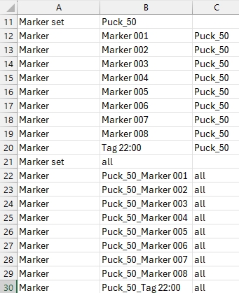
In the data export, a marker set is the group of markers that make up a specific asset. They are presented twice in the .csv file, first by the individual asset and then combined into a single list, the marker set "all."
Individual asset data displays the simplified marker name in column B and the asset name in column C.
the Marker set named "all" contains every marker tracked in the take as part of a skeleton or rigid body asset. This set displays the marker with the asset name as a prefix in column B, and identifies the marker set as "all" in column C.
Camera Descriptions
The cameras used in the Take are listed at the bottom of the export file.
Column B lists the camera's model and serial number.
Columns C, D, and E list the camera's X/Y/Z coordinates.
Columns F, G, H, and I list the camera's quaternion values.
Device Data
For Takes containing active devices (Active Puck or CinePuck) force plates (AMTI or Bertec) or data acquisition (NI-DAQ) devices, additional CSV files will be exported for each connected device. For example, if you have two force plates and a NI-DAQ device in the setup, a total of four CSV files will be created when you export the tracking data from Motive (five, if the Data Description file is also exported). Each of the exported CSV files will contain basic properties and settings at its header, including device information and sample counts. Also, mocap frame rate to device sampling rate ratio is included since force plate and analog data are sampled at higher sampling rates.
Since device data is usually sampled at a higher rate than the camera system, the camera samples are collected at the center of the corresponding device data samples that were collected. For example, if the device data has 9 sub-frames for each camera frame sample, the camera tracking data will be recorded at every 5th frame of device data.
Force Plate Data: Each of the force plate CSV files will contain basic properties such as platform dimensions and mechanical-to-electrical center offset values. The mocap frame number, force plate sample number, forces (Fx/Fy/Fz), moments (Mx, My, Mz), and location of the center of pressure (Cx, Cy, Cz) will be listed below the header.
Analog Data: Each of the analog data CSV files contains analog voltages from each configured channel.
Active Device IMU Data: Exports location data for the specified IMU.
Physical Markers vs Marker Constraints During Occlusion
Rigid Body markers, trained markerset markers, and Skeleton bone markers have corresponding Marker Constraints that are included in the export. Constraints appear as transparent spheres within an asset, and each sphere reflects the position where the asset definition expects to find a 3D marker. When the asset definitions are created, it is assumed that the markers are in fixed positions relative to one another and that these relative positions do not shift over the course of capture.
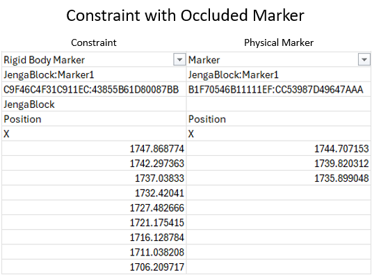
In the CSV file, Rigid Body markers have a physical marker column and a Marker Constraints column.
When a marker is occluded in Motive, the Marker Constraints will display the solved position for where the marker should be in the CSV file. The actual physical marker will display a blank cell or null value since Motive cannot account for its actual location due to its occlusion.
CSV Header
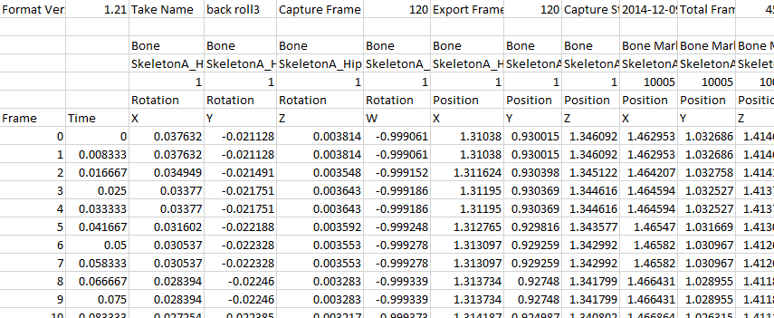
When the header is disabled, this information is excluded from the CSV files. Instead, the file will have frame IDs in the first column, time data on the second column, and the corresponding mocap data in the remaining columns.
1st row
General information about the Take and export settings: Format version of the CSV export, name of the TAK file, the captured frame rate, the export frame rate, capture start time, capture start frame, number of total frames, total exported frames, rotation type, length units, and coordinate space type.
2nd row
Empty
3rd row
Displays which data type is listed in each corresponding column. Data types include raw marker, Rigid Body, Rigid Body marker, bone, bone marker, or unlabeled marker. Read more about Marker Types.
4th row
Includes marker or asset labels for each corresponding data set.
5th row
Displays marker or asset ID.
6th and 7th rows
Shows which data is included in the column: rotation or position and orientation on X/Y/Z.
TIP: Occlusion in the marker data
When there is an occlusion of a marker, the CSV file will contain blank cells, which can interfere when running a script to process the CSV data.
We recommend optimizing the system setup to reduce occlusions. To omit unnecessary frame ranges with frequent marker occlusions, select the frame range with the most complete tracking results.
Another solution is to use Fill Gaps to interpolate missing trajectories in post-processing.
Was this helpful?

