Continuous Calibration Pane
An overview of the Continuous Calibration pane and its functions.
Overview
The Continuous Calibration pane is used to manage and monitor the Continuous Calibration process. This pane is accessed under the View tab in Motive or by clicking the ![]() icon on the main toolbar.
icon on the main toolbar.
The Continuous Calibration feature can be enabled from either the Calibration pane or the Continuous Calibration pane.

Camera Samples
The Camera Samples section provides a visual aid to show which cameras need more marker samples or a better distribution of marker samples for Continuous Calibration to work.
More Markers
A minimum of four markers are required for continuous calibration to work. The More Markers section displays the cameras that require additional markers in their field of view to meet the minimum.

Click any of the camera buttons within the Camera Samples section to select the camera. This will also select the camera in the 2D Camera Viewport and Devices pane.
If a camera appears under More Markers:
Select the camera under More Markers.
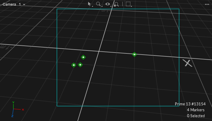
Navigate to the 2D Viewport and from the top left dropdown select From Camera x.
The Viewport will show the camera's field of view and any markers it can see within the cyan box.
Add additional markers within the camera's view until the camera button is removed from More Markers.

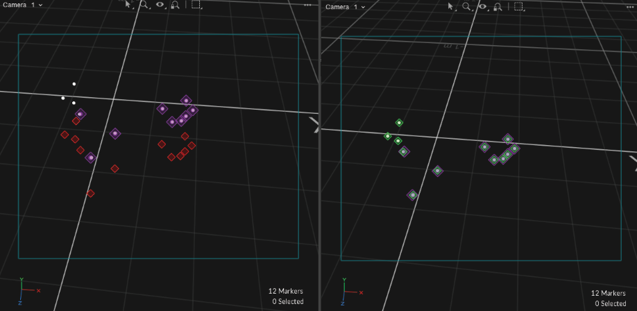
Markers within the field of view that are receiving good tracking rays will appear with a green diamond encompassing the marker.
Markers outside of the FOV will appear standard white.
Markers within FOV that have untracked rays will appear with a red diamond encompassing the marker.
Better Distribution
You may have enough markers so that there are no cameras listed under More Markers, but still see cameras under Better Distribution.
Select a camera listed under Better Distribution.
Navigate to the 2D Viewport and from the top left dropdown select From Camera x.
This will show the camera's field of view and any markers that it can see within the cyan box.
Add additional markers that are more evenly distributed within the camera's view.

For Better Distribution, oftentimes all you need is a single additional marker separated from another cluster of markers, as seen in the image above.
Anchor Markers
Anchor markers can further improve continuous calibration. When properly configured, anchor markers improve continuous calibration updates, especially on systems that consists of multiple sets of cameras that are separated into different tracking areas, by obstructions or walls, without camera view overlap.
Anchor Markers also provide extra assurance that the global origin will not shift during each Continuous Calibration update, although the Continuous Calibration feature itself already checks for this.

The Anchor Markers section allows you to add/remove and import/export Anchor markers. It also shows the mean error under the Distance column for each individual Anchor marker and the overall in the top right in millimeters.
Right click the header to add or remove columns, such as the Active ID column.
When the icon in the top right is a green circle with a check, all Anchor markers are visible by at least one camera.
When the icon is a red circle with an x, at least one Anchor marker is occluded from all cameras.
For additional information regarding Anchor markers, please see this page.
Partitions

For multi-room setups, it is useful to group cameras into partitions. This allows for Continuous Calibration to run in each individual room without the need for camera view overlap.
The Partitions section directly corresponds with Partitions created in the Properties pane for each individual camera. This section displays the status of Continuous Calibration for each partition.
For more information, please see the Partitions section here.
If a Partition or Partitions are not receiving enough marker data to validate or update, they will appear magenta in the table and a red circle with an x icon will appear in the top right of the section.
Partition Table Columns
No.
This is the Partition ID assigned via the camera's Properties pane. By default this value is 1.
Status
Idle - Continuous Calibration is either turned off or there are not enough markers for Continuous Calibration to begin sampling.
Sampling - Continuous Calibration is collecting marker samples.
Evaluating - Continuous Calibration is determining if the latest samples are better than the previous and will update if necessary.
Processing - Processing will occur when an update is processing.
Last Validated
Last Validated will update the timestamp to 0h 0m 0s when the samples have been collected and the calibration solution was not deemed to be better than the solution already in place.
Last Updated
Last Updated will update the timestamp to 0h 0m 0s when good samples were collected and the calibration solution was deemed better than the solution in place.
Error
This is the mean ray error for each partition in millimeters. The overall mean ray error will be displayed in the top right corner of the section.
Anchors
This column denotes the number of Anchor markers that are visible within a partition.
Partitions Settings
Click the ![]() button at the bottom of the Continuous Calibration pane to open the Settings panel.
button at the bottom of the Continuous Calibration pane to open the Settings panel.

The Partitions settings establish the thresholds that determine the quality of the partition's calibration. If a partition fails to meet any of the set thresholds, the row will turn magenta in the Partitions list.

Maximum Error
If the ray error for a Partition exceeds the Maximum Error value, the text in the Partition's row will change to magenta and the icon on the top right of the Partition section will display a red circle with an 'x'.
This setting can be changed to any positive decimal.
Maximum Last Updated
Maximum Last Updated dictates how long Continuous Calibration can go without an update before the user is alerted (by a magenta text and a red circle with an 'x' icon) that Continuous Calibration has not been updated.
Bumped Cameras
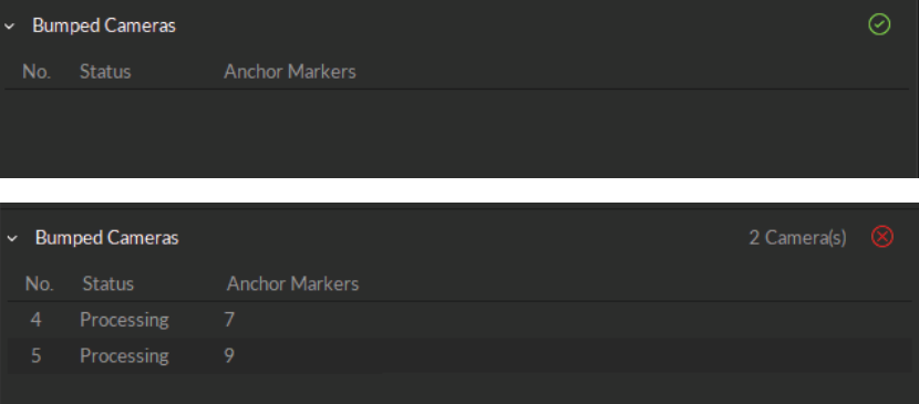
The Bumped Cameras features corrects a camera's position in Motive if it is physically bumped in the real 3D space.

Quick Start Guide
Bumped Cameras needs to be enabled in the Info pane when initializing Continuous Calibration for any fixes to be applied. If it is NOT enabled and a camera is physically displaced, you will need to run a full Calibration to ensure accurate tracking.
Create Anchor markers from the Anchor Markers section or add Active markers.
Enable Bumped Cameras from the Bumped Cameras Settings:
Select Camera Samples for Mode.
Select either Anchor Markers, Active Markers, or Both from Marker Type.
Bumped Cameras is now able to correct physical camera movement without needing a full Calibration.
To see the results of Bumped Cameras steps above you can do the following:
The steps below are not necessary, but something you can do to see Bumped Cameras work in action.
Select the camera's view you intend to physically move in the 2D Camera Viewport.
Make sure Tracked and Untracked Rays are visible from the 'eye' icon in the 2D Camera Viewport.
Physically move the camera so that the markers appear with a red diamond around them (untracked).
Wait a few seconds and notice the camera's view shift to correct in the 2D Camera Viewport.
The red diamonds should now be green.

Bumped Cameras Settings

Mode
Disabled - When Mode is set to Disabled, Bumped Camera correction will not apply.
Camera Samples - When Mode is set to Camera Samples, Bumped Camera correction will correct based on the Camera Samples data. If Camera Samples is populated with cameras this will trigger Bumped Cameras to correct any cameras that may have moved. If a camera has NOT moved, this camera will remain idle in the Bumped Camera section until Camera Samples is clear of needed samples or distribution.
Selected Cameras - When Mode is set to Selected Cameras, this will ONLY correct the camera that is selected by the user from either the Devices, 3D or 2D viewport, or Camera Samples.
A camera MUST be selected during a bump for Selected Cameras mode to correct the camera's position.
It must also be de-selected after the camera posistion has been corrected, else the feature will continue to consume high CPU resources and left long term could have a negative effect in quality tracking.
Marker Type
Anchor Markers - ONLY Anchor Markers will be used to collect data for Bumped Cameras to correct a camera's position.
Active Markers - ONLY Active Markers will be used to collect data for Bumped Cameras to correct a camera's position.
Anchor and Active - BOTH Anchor and Active Markers will be used to collect data for Bumped Cameras to correct a camera's position.
Max Camera Count
If you only wish to have a few cameras corrected you can lower the count of the Max Camera Count. By default this is set to 20.
Last updated
Was this helpful?

