External Device Sync Guide: eSync 2

Overview

This page provides general instructions on how to use the eSync 2 for synchronizing external devices.

The eSync 2 is a synchronization hub that allows advanced users to integrate external systems into OptiTrack motion capture systems. With proper sync chain setups, you can have another (parent) system control the mocap system, or have the mocap system control other (child) systems, or both. Note that the setup may change depending on the type and number of the external devices as well as the characteristics of the communicated sync signals. Use this guide for understanding the general idea of how external devices are implemented and apply the knowledge for your needs.

External Device Synchronization

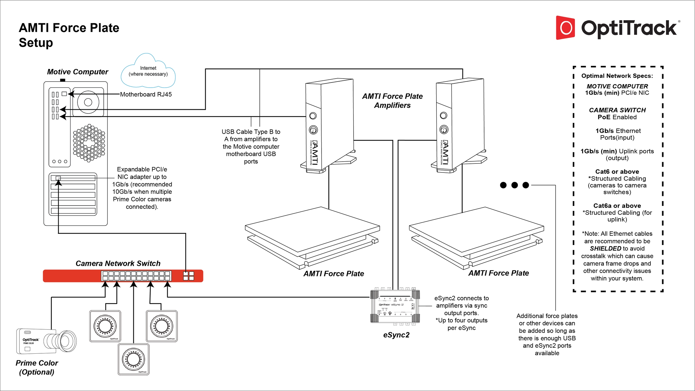
With the eSync 2, Prime series mocap systems can work together with other systems to perform precisely synchronized operations and data collections. This offers benefits in a wide range of applications. Reference video cameras, NI-DAQ devices, Force Plates, and recording triggers are examples of commonly synchronized external devices.

The eSync 2 synchronization hub has multiple sync input and output ports. In general, a parent device connects to the input ports for controlling the mocap system, and the child devices connect to output ports to be controlled by the mocap system. Once the devices are connected to the eSync 2, the input and output signal characteristics need to be specified and configured under the eSync 2's device properties in Motive.

Requirements

  • Ethernet Camera System (PrimeX series or SlimX 13)

  • The eSync 2

  • External Devices (child / parent)

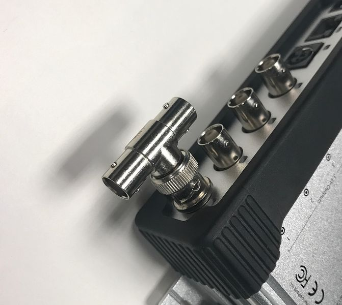
  • Sync Cables: BNC or other sync cables with BNC adapters.

The eSync 2

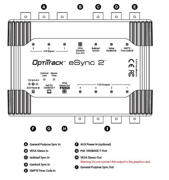
For eSync 2 technical specifications please visit our eSync 2 Support webpage.

Synchronization Setup

For general instructions on setting up the mocap system, refer to the Hardware Setup pages. This guide assumes the camera system and the eSync 2 have been already set up.

Step 1. Before setting up, draw out the schematic of which devices will be the parent or the child of the synchronization chain in respect to the mocap system.

Step 2. Connect the external devices

  • Child Devices (e.g. Force Plates): Connect Output ports of the eSync 2 into sync input ports of the child devices

  • Parent Device (e.g. Genlock): Connect the sync output of a parent device into one of the Input ports of the eSync 2. For integrating Genlock, VESA Stereo In, or SMPTE timecode signals, connect them to the corresponding labeled input ports of the eSync 2.

Step 3. Launch Motive. The eSync 2 should get listed under the Devices pane.

Step 4. [Motive] Open the Properties pane and select the eSync 2 in the Devices pane to access its properties.

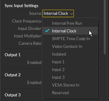
Step 5. [Motive > Properties: eSync 2] Under the Sync Input Settings: Source section, use the drop-down menu to pick a desired sync source for the camera system to synchronize to. Read more under the Input Source Setup section of this page.

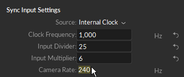
Step 6. [Motive > Properties: eSync 2] Configure the input divider/multiplier settings, and/or the clock frequency settings (for Internal Clock only), to set the camera rate. The final frame rate of the camera system will be displayed next to Camera Rate property or in the Devices pane.

Step 7. [Motive > Properties: eSync 2] Configure the Outputs. Output ports of the eSync 2 are used to tell connected child devices what Motive is doing. Read more under the Output Signal Setup section of this page.

Step 8. [Motive > Properties: eSync 2] If you wish to set up a recording trigger device, connect it to one of the input ports and designate the port under the Recording Trigger section of the eSync 2 properties. Read more under the Recording Trigger Setup section of this page.

Step 9. [Motive > Properties: eSync 2] Lastly, check the Monitor section and make sure all signals are detected properly.

Input Source Setup

Once you have connected the external devices to the eSync 2, the first step is to select and configure the sync source under th eSync 2 properties. The selected source will become the parent sync of both the camera system and other external devices. There are multiple sync source options to choose from under the drop-down menu. Ultimately, only one sync source will be selected and used to synchronize the cameras and subsequent child devices for any particular configuration.

When you are done changing the settings, press Apply to set the configured sync method.

Sync Input: Select the Sync Source

The first step is to define a parent sync source for the camera system. This is configured in the Sync Input → Source entry under the eSync 2 properties:

Internal Free Run

By default, the sync input source is set to Internal Free Run, meaning that the camera system is sampling at a frame rate defined in the Devices pane. In this mode, Prime series cameras are synchronized by communicating the time information with each other through the camera network itself using a high-precision algorithm for timing synchronization. This is the default synchronization protocol for Ethernet camera systems without an eSync 2.

Internal Clock

To use the internal clock of the eSync 2 as the parent sync source for both the camera system and the subsequent child devices, set the sync input source to Internal Clock. When selected, the clock frequency can be adjusted in Sync Input → Clock Freq (Hz) settings.

Input Signal

To use an external sync signal as the parent sync source, set the sync input source to the corresponding input port where the parent device is connected to. See the specifications for more details on each of the input ports.− Input ports (1-3): VIH(max): 3.3V− Isolated Input port: VIH(max): 12V− VESA Stereo Input port: VIH(max): 3.3V− Video Genlock In and SMPTE Timecode

Sync Input: Set the Input Trigger

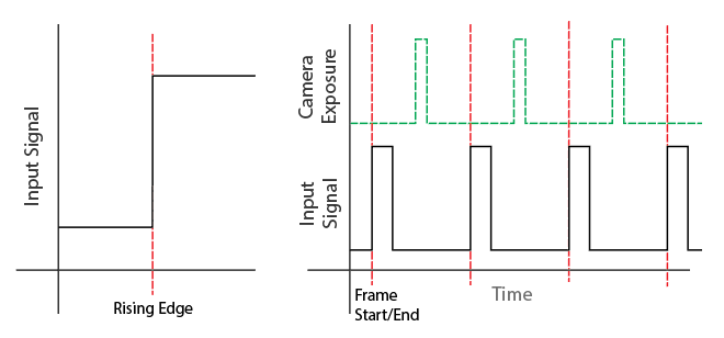
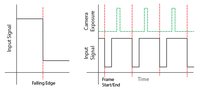
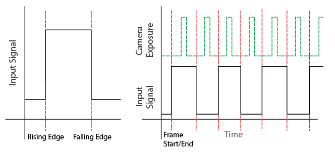
Once the input source is set, next step is to define an appropriate trigger event. Under the Sync Input → Input Trigger option, pick a signal morphology (Either Edge, Rising Edge, or Falling Edge) for the desired trigger event. Note that the suitable event will vary depending on characteristics of the received signal and how you want the system to synchronize with it. The following diagrams show how the camera system responds to received signal triggers. When configured properly, the camera system will expose in respect to the sync signal from the parent device.

Rising Edge:

Every rising edge of the sync input signal defines either the start or the end of a frame, consecutively.

Falling Edge:

Every falling edge of the sync input signal defines either the start or the end of a frame, consecutively.

Either Edge:

Every rising or falling edge of the sync input signal defines either the start or the end of a frame, consecutively. When using both of the edges as the input trigger, the input signal must have 50% duty cycle for the cameras to synchronize properly.

Set the Input Divider/Multiplier

The frame rate of the camera system gets determined by the selected sync input source. When the frequency of the sync source is higher than the supported frame rate, input dividers and multiplier can be applied to adjust the signal frequency for synchronizing the camera system. The final framerate will be calculated and displayed at the bottom, Sync Input → Final Frame Rate, and you can monitor this rate while you apply the adjustments. When the customized sync configurations are applied at the end of the setup, the cameras will start to capture at this final frame rate.

Set Sync Offset

Advanced: Sync Input Trigger and Exposure Timing
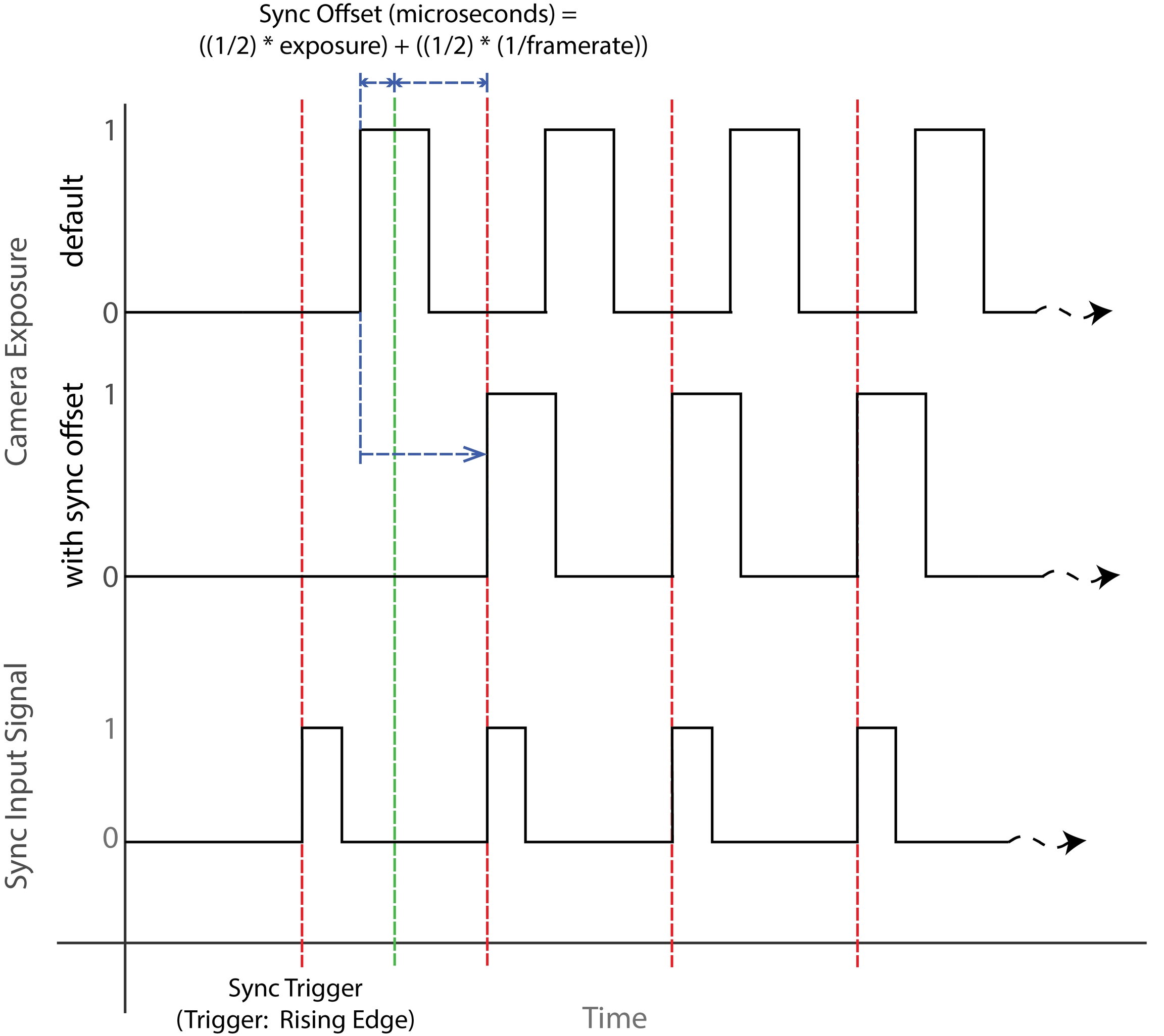
Camera exposures are always positioned at the center of every frame periods, and the precise moment of the camera exposure does not exactly coincide with the trigger event. When synchronizing the camera exposure timing with the sync input signal triggers, make sure this gap is taken into account. To precisely align the input signal trigger with the exposure timing, an offset delay, in microseconds, of half of the frame period plus half of the camera exposure must be applied in the Sync Input → Sync Offset (us). The camera exposure is measured in microseconds on the Ethernet cameras.

Output Source Setup

The eSync 2 has total 4 output ports (3.3 V). If you want to setup the camera system to be a parent of other systems, connect the child devices into the Output ports of the eSync for receiving the reference sync signals. Once the devices are connected, you can configure the output signal source under the eSync 2 properties. Know what type of sync signals are expected by the child devices, and configure the sources accordingly so that appropriate signals are outputted.

The eSync 2 can output the following types of signals:

  • Exposure Time

  • Recording Gate

  • Record Start/Stop Pulse

  • Gated Exposure Time

  • Gated Internal Clock

  • Selected Sync

  • Adjusted Sync

  • Input signals: Relaying input signals.

    • Selected Sync: Raw input signal.

    • Adjusted Sync: Adjusted (offset, multiplier, and divider) signal.

Note: All output signals can be inverted by setting the Output → Polarity to Inverted.

Gated Output Signal (eSync 2):

The gated (while-recording) output signal from the eSync 2 is frame-synchronous with the recorded mocap data. In the live mode, the cameras are continuously shuttering and capturing frames at a defined frame rate. If the recording trigger is received in the middle of a frame period, the eSync waits until the next frame to start recording and asserting gated output signal. This mechanism ensures that the recorded mocap data and the gated output signals are precisely synchronized.

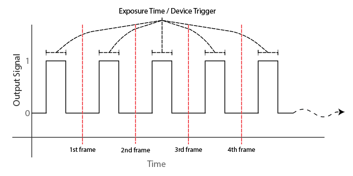
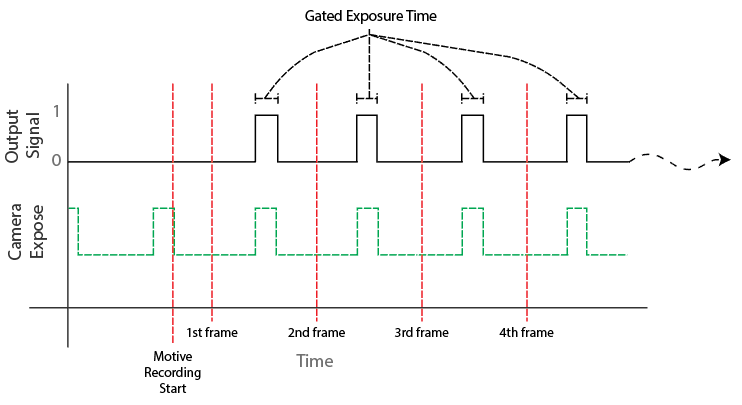
Exposure Time / Gated Exposure Time

Exposure Time/Gated Exposure Time output signals indicate when the cameras are exposing.

When the Output:Type is set to Exposure Time, a high voltage (3.3V) signal will be outputted from the corresponding output port whenever the camera system is exposing, or shuttering, in the Live Mode. The Gated Exposure Time signal works similarly, but the signal will be sent out only when Motive is recording.

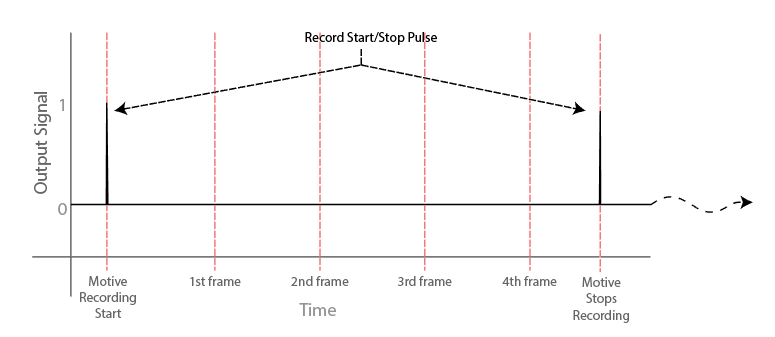
Recording Gate & Recording Start/Stop Pulse
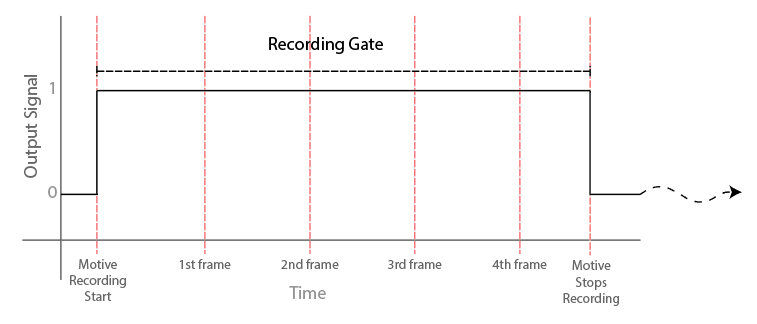
Recording gate/pulse output signals can be used to tell the child device when Motive is recording or not. When configured to Recording Gate, the eSync 2 will output a constant high voltage signal when Motive is recording. When configured to Recording Start/Stop Pulse, the sync hub will output a pulse signal when Motive either starts or stops recording.

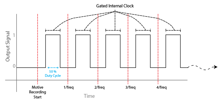
Gated Internal Clock

When configured to Gated Internal Clock, the eSync 2 outputs its internal clock signal while Motive is recording. The internal clock signal has a 50% duty cycle with the signal frequency defined under the Sync Input → Clock Freq (Hz) section.

Using Internal Clock Signal to drive both the camera system and external devices

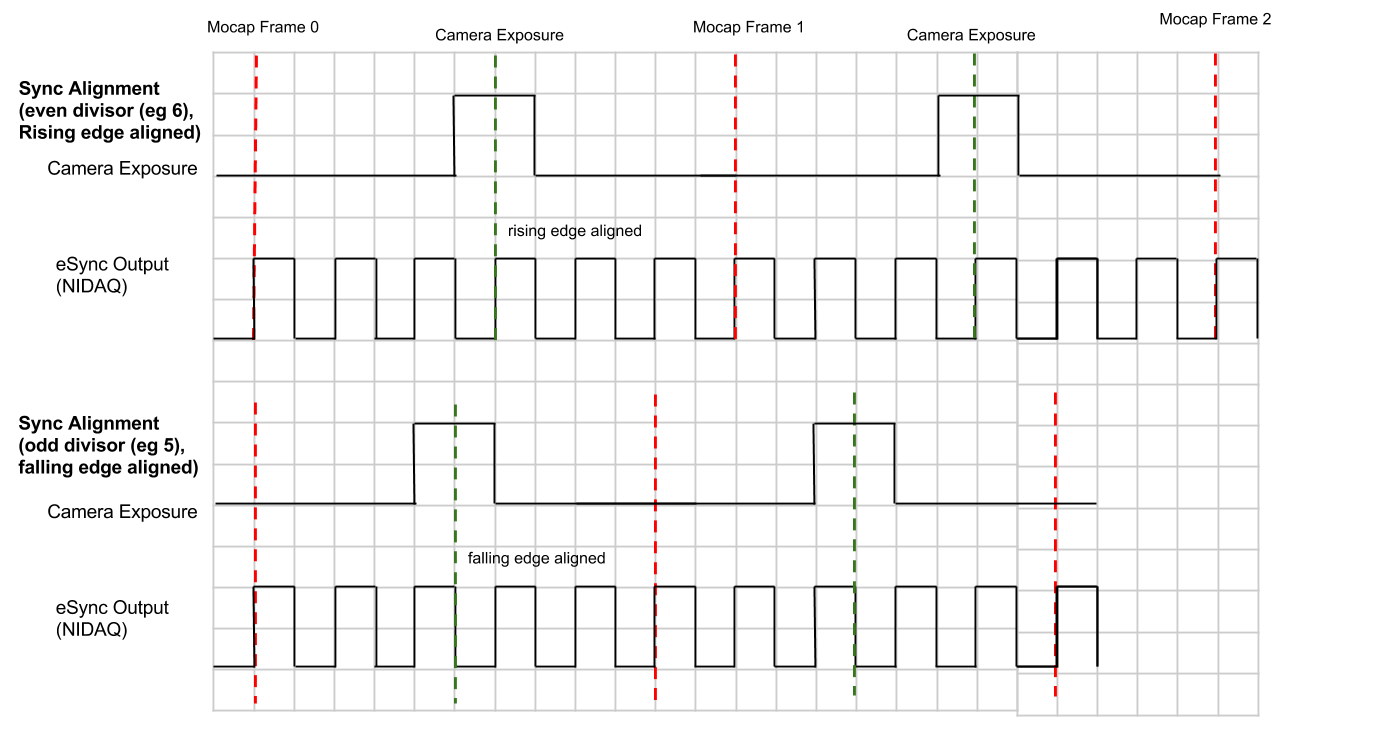
To achieve per-frame synchronization between the camera system and an external device (e.g. force plates, NI-DAQ), the internal clock signal from the eSync 2 can be used to drive both the camera system as well as the external device. This is possible only if the external device has the capability of receiving external clock signal. When the external system runs at a higher sampling rate, a divisor or a multiplier must be applied to the clock signal to achieve the desired framerate on the camera system. Here, please note that depending on the applied divisor/multiplier, the alignment of the outputted signal may vary. The exposure timing of the camera system will always be aligned at the center of the divided or multiplied signal, and whether the exposure timing aligns with the rising edge or falling edge of the output signal may vary depending on the applied divisor. Please see the below image:

Hardware Recording Trigger Setup

With the eSync 2, external triggering devices (e.g. remote start/stop button) can integrate into the camera system and set to trigger the recording start and stop events in Motive. Such devices will connect to input ports of the eSync 2 and configured under the Record Triggering section of the eSync 2 properties.

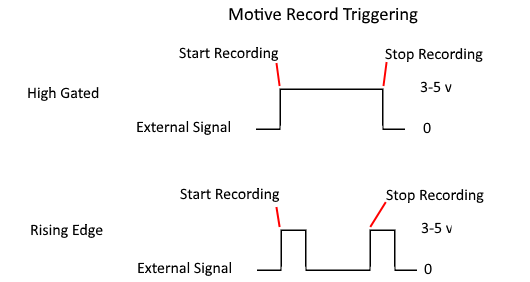
By default, the remote trigger source is set to Software, which is the record start/stop button click events in Motive. Set the trigger source to the corresponding input port and select an appropriate trigger edge when an external trigger source (Trigger Source → isolated or input) is used. Available trigger options include Rising Edge, Falling Edge, High Gated, or Low Gated. The appropriate trigger option will depend on the signal morphology of the external trigger. After the trigger setting have been defined, press the recording button in advance. It sets Motive into a standby mode until the trigger signal is detected through the eSync 2. When the trigger signal is detected, Motive will start the actual recording. The recording will be stopped and return to the 'armed' state when the second trigger signal, or the falling edge of the gated signal, is detected.

Note: For capturing multiple recordings via recording trigger, only the first TAK will contain the 3D data. For the subsequent TAKs_, the 3D data must be reconstructed through the_ post-processing reconstruction pipeline.

Steps

  1. Open the Devices pane and the Properties pane to access the eSync 2 properties.

  2. Under the Record Triggering section, set the source to the respective input port where the trigger signal is inputted.

  3. Choose an appropriate trigger option, depending on the morphology of the trigger signal.

  4. Press the record button in Motive, which prepares Motive for recording. At this stage, Motive awaits for an incoming trigger signal.

  5. When the first trigger is detected, Motive starts recording.

  6. When the second trigger is detected, Motive stops recording and awaits for next trigger for repeated recordings. For High Gated and Low Gated trigger options, Motive will record during respective gated windows.

  7. Once all the recording is finished, press the stop button to disarm Motive.

Troubleshooting

Q : I have set up a custom synchronization chain from a mocap system (parent) to a third-party device (child) that uses a third-party software package to operate, but somehow I am seeing a timing offset between the two recorded data sets. What's happening here?

A: The observed offset is likely due to a time delay from the third party system receiving the signal and initiating the recording. This is a common source of confusion especially for syncing devices that runs on third-party software packages.

The eSync and the OptiHub can be configured to output signals at specified events (e.g. exposure timing, recording pulse, etc.). However, this configuration solely will not accomplish precise synchronization of the two systems because it does not take account of the time delay it takes for the third party system to receive and react to the signal.

To achieve fully precise synchronization, please follow our device specific sync setup guides, if applicable, or take this offset into consideration.