.mcal XML Calibration Files
An overview of the data available in the .mcal calibration file.
Last updated
Was this helpful?
An overview of the data available in the .mcal calibration file.
Last updated
Was this helpful?
Beginning with Motive 3.2, calibration data is stored in an XML file with the file extension .mcal. XML is a human-readable format that can be imported for use in end-user applications.
This page defines the properties in the .mcal file that could be used in third-party applications.
The serial number of the camera. In Motive, this information is located in the section of the .
Properties related to the specified camera, as defined in the pane in Motive.
The camera number assigned by Motive. In the Properties pane, this is shown in the .
This value corresponds to the letter prefix in the device serial number, when present. Pre-set values are used for USB-connected devices.
Prime Cameras
M
00
USB Cameras
None
00
Tracking Bar Cameras Primary
None
01
Tracking Bar Cameras Secondary
None
02
Tracking Bar Cameras Tertiary
None
03
OptiTrack IO X Duo & Trio Device Break-out Connectors
None
0F
eSync Devices
ES
10
Golftec Cameras
GT
20
Color Cameras
C
30
Active Devices
A
40
Leyard Cameras
L
50
The amount of time, in microseconds, that the camera exposes per frame.
The minimum brightness required for a camera to detect a pixel. All pixels below the stated threshold will be ignored.
This is a legacy setting related to LED power.
Indicates whether the camera's infrared lights are set to strobe (0) or to remain on continuously (1).
Indicates the video mode of the camera.
2
Object
4
Precision
1
Grayscale
6
MJPEG
The camera system frame rate.
Indicates the ratio of frames displayed per total frames captured.
Frame Decimation is not supported in all devices.
0
1:1
3
1:4
7
1:8
15
1:16
Indicates the ratio of frames displayed per total frames captured when in Grayscale mode.
Grayscale decimation is not supported in all devices.
0
1:1
2
1:4
4
1:16
For cameras in MJPEG mode, this value indicates the quality of the video recording.
25
Minimum
50
Low
75
Medium
100
High
Indicates whether the camera is set to view infrared spectrum (0) or visible (1) light.
This is a legacy property that no longer affects the system calibration.
Indicates if high power mode is on (1) or off (0) for applicable cameras.
Indicates the imager gain level for the selected camera. Gain settings can be adjusted to amplify or diminish the brightness of the image.
Indicates whether the camera is enabled (1) or disabled (0) from contributing to the reconstruction of 3D data, when recording in object mode.
Internal reference information for the camera.
The internal camera model number.
The camera group number that the selected camera is in.
Defines the center point of the imager on the x-axis.
Defines the center point of the imager on the y-axis.
Intrinsic values are fixed characteristics of the lens and are used to adjust for lens distortion. These values are not displayed in Motive.
The calibration file contains two types of intrinsic values:
OptiTrack Internal Model. Values optimized for Motive's internal calibration calculation. This model is not applicable for use in other contexts.
Standard Camera Model. Standardized values that provide accurate results when exported to the OpenCV model.
The location of the lens center on the imager, on the X axis.
The location of the lens center on the imager, on the Y axis.
The Focal Length of the imager along the Y axis, in pixels.
The Focal Length of the imager along the X axis, in pixels.
K values control the amount of radial distortion applied to the image.
Tangential values account for the distortion that occurs when the imager and the lens are not aligned in parallel. TangentialX is the amount of tilt off the X axis, while TangentialY is the amount of tilt off the Y axis.
The camera's location in X/Y/Z coordinates.
Values that comprise the rotation matrix where the camera's rotation values are stored. Motive uses Row Major rotation matrices.
Indicates the Filter Type to apply to a 2D object for it to be included in the Point Cloud reconstruction. Possible choices are Size & Roundness (2). or None (0).
The minimum pixel size for a 2D object to be included in the Point Cloud reconstruction.
The maximum pixel size for a 2D object to be included in the Point Cloud reconstruction.
The minimum circularity threshold a 2D object must meet to be included in the Point Cloud reconstruction.
The pixel intensity of the grayscale floor.
The minimum number of pixels required between objects before they begin to overlap.
The number of pixels a 2D object is allowed to lean.
The maximum allowable aspect tolerance to process a 2D object (width:height).
The allowable aspect tolerance for very small objects.
The rate at which the aspect tolerance relaxes as object size increase.
Indicates whether the intrusion band setting is on (1) or off (0).
The size of the guard region beyond the object margin for neighbor detection. Corresponds to the Intrusion Band property.
The partition group assigned to the camera for continuous calibration.
This property sets the resolution of the images captured by the selected camera.
0
1080
1
720
2
540
3
272
The type of compression that will be applied to the captured images.
1
Constant Bit-Rate
0
Variable Bit-Rate
The percentage of the maximum data transmission speed to allocate for the camera.
The selected color camera's output transmission rate, as a fraction of the maximum (100 MB/s).
The camera sub-model, as shown in the Camera details.
The .mcal XML file can be exported for use with the OpenCV platform.
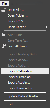
From the File menu, select Export Calibration...
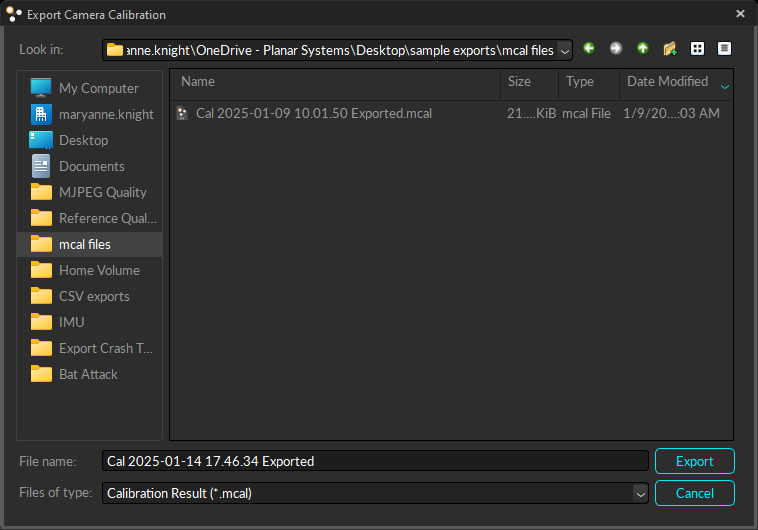
Browse to the directory where you would like the file exported to.
The default file name includes the timestamp of the export, not for the calibration itself.
Indicates the angle of the camera's view. This property can be adjusted in Motive from the menu in the .
Indicates whether the setting is enabled (1) or not (0).
These values are found in the of the Camera Properties in Motive.
Extrinsic values define the physical location of the camera. In Motive, the position values are shown in the Details section of .
Camera Software filter properties are found on the . Some are advanced settings.
Camera Hardware filter properties are found on the . All are advanced settings.
Camera properties relevant to continuous calibration are found in the pane.
Additional properties specific to Color Cameras are located in the pane. These properties are not included in the .mcal file if there are no color cameras present.
This value is applicable only when the is set to 1 (Constant Bit-Rate).
The amount of correction applied to the selected camera's output image.