LogoLogo
WebsiteSupportDownloadsForumsQuick LinksContact Us
v3.2
v3.2
  • OptiTrack Documentation
  • WHAT'S NEW
    • What's New in Motive 3.2
  • QUICK START GUIDES
    • Quick Start Guide: Getting Started
    • Quick Start Guide: Prime Color Camera Setup
    • Quick Start Guide: Precision Capture
    • Quick Start Guide: Tutorial Videos
    • Quick Start Guide: Active Marker Tracking
    • Quick Start Guide: Outdoor Tracking Setup
  • HARDWARE
    • Cameras
      • Ethernet Cameras
        • PrimeX 120
        • PrimeX 41
        • PrimeX 22
        • PrimeX 13
        • PrimeX 13W
        • SlimX 13
        • Prime Color
        • VersaX 22
        • VersaX 41
        • VersaX 120
      • USB Cameras
        • Slim 3U
        • Flex 13
        • Flex 3
        • V120:Duo
        • V120:Trio
        • Adjusting Global Origin for Tracking Bars
    • Prepare Setup Area
    • Camera Mount Structures
    • Camera Placement
    • Ethernet Camera Network Setup
      • General Overview and Specs
      • Windows 10 Network Settings
      • Cabling and Load Balancing
      • Switch Configuration for PrimeX 120
      • NETGEAR ProSafe GSM7228S: Disabling the Broadcast Storm Control
      • White/Blacklisting Cameras
    • USB Camera System Setup
      • USB Camera Network Overview and Specs
      • V120:Duo and Trio Setup
      • Tracking Bar Coordinate System
        • Transforming Coordinate System: Global to Local
    • Aiming and Focusing
    • Camera Status Indicators
  • MOTIVE
    • Installation and License Activation
    • Motive Basics
    • Calibration
      • .mcal XML Calibration Files
      • Continuous Calibration
      • Continuous Calibration (Info Pane)
      • Calibration Squares
    • Markers
    • Assets
      • Gizmo Tool: Translate, Rotate, and Scale
    • Rigid Body Tracking
      • Aligning Rigid Body Pivot Point with a Replicated 3D Model
    • Skeleton Tracking
    • Trained Markersets
    • IMU Sensor Fusion
    • Data Recording
      • Data Types
    • Labeling
    • Data Editing
    • Data Export
      • Data Export: BVH
      • Data Export: C3D
      • Data Export: CSV
      • Data Export: FBX
      • Data Export: TRC
    • Data Streaming
    • Camera Video Types
    • Audio Recording
    • Motive HotKeys
    • Measurement Probe Kit Guide
    • Motive Batch Processor
    • Reconstruction and 2D Mode
  • MOTIVE UI PANES
    • Settings
      • Settings: General
      • Settings: Assets
      • Settings: Live Pipeline
      • Settings: Streaming
      • Settings: Views
      • Settings: Mouse and Keyboard
      • Settings: Audio
    • Assets Pane
    • Builder Pane
    • Constraints Pane
      • Constraints XML Files
    • Calibration Pane
    • Data Pane
    • Devices Pane
    • Edit Tools Pane
    • Graph View Pane
    • Info Pane
    • Labels Pane
    • Log Pane
    • Probe Pane
    • Properties Pane
      • Properties Pane: Camera
      • Properties Pane: Force Plates
      • Properties Pane: NI-DAQ
      • Properties Pane: OptiHub2
      • Properties Pane: Rigid Body
      • Properties Pane: Skeleton
      • Properties Pane: Take
      • Properties Pane: Trained Markerset
      • Properties Pane: eSync2
    • Status Panel
    • Toolbar/Command Bar
    • Control Deck
    • Viewport
  • PLUGINS
    • OptiTrack Blender Plugin
      • OptiTrack Blender Plugin
    • OptiTrack Unreal Engine Plugin
      • Unreal Engine: OptiTrack Live Link Plugin
        • Quick Start Guide: Real-Time Retargeting in Unreal Engine with Live Link Content
        • Unreal Editor for Fortnite (UEFN): OptiTrack Plugin for Live Link Hub
        • Unreal Engine: Live Link Camera Stream Setup
        • Live Link Content: Active Puck Static Meshes
      • Unreal Engine: MotionBuilder Workflow
      • Unreal Engine: HMD Setup
      • Unreal Engine VCS Inputs
    • OptiTrack Unity Plugin
      • Unity: HMD Setup
    • OptiTrack OpenVR Driver
    • OptiTrack MATLAB Plugin
    • Autodesk Maya
      • Autodesk Maya: OptiTrack Insight VCS Plugin
    • Autodesk MotionBuilder
      • Autodesk MotionBuilder Plugin
      • Autodesk MotionBuilder: OptiTrack Skeleton Plugin
      • Autodesk MotionBuilder: OptiTrack Optical Plugin
      • Autodesk MotionBuilder: OptiTrack Insight VCS Plugin
      • Autodesk MotionBuilder: Timecode Data
    • OptiTrack Peripheral API
    • External Plugins
      • Houdini 19 Integration
  • ACTIVE COMPONENTS
    • Active Components Hardware
      • Active Puck
      • Wired AnchorPuck
      • CinePuck
      • Wired CinePuck
      • BaseStation
      • Information for Assembling the Active Tags
      • Manus Glove Setup
    • Configuration
      • Active Batch Programmer
      • Active Hardware Configuration: PuTTY
      • Active Component Firmware Compatibility
    • Active Marker Tracking
      • Active Finger Marker Set
  • SYNCHRONIZATION
    • Synchronization Hardware
      • External Device Sync Guide: eSync 2
      • External Device Sync Guide: OptiHub2
    • Synchronization Setup
    • OptiTrack Timecode
  • VIRTUAL PRODUCTION
    • Unreal Engine: OptiTrack InCamera VFX
    • Entertainment Marker Sets
    • PrimeX 41
  • MOVEMENT SCIENCES
    • Movement Sciences Hardware
      • General Motive Force Plate Setup
      • AMTI Force Plate Setup
      • Bertec Force Plate Setup
      • Kistler Force Plate Setup
      • Delsys EMG Setup
      • NI-DAQ Setup
      • Multiple Device Setup
    • Movement Sciences Marker Sets
      • Biomechanics Marker Sets
      • Biomech (57)
      • Rizzoli Marker Sets
    • For Visual3D Users
    • Prime Color Camera Setup
      • Prime Color Setup: Required Components
      • Prime Color Setup: Hardware Setup
      • Prime Color Camera Setup: Camera Settings
      • Prime Color Camera Setup: Prime Color FS Calibration
      • Prime Color Setup: Data Recording / Export
      • Prime Color Camera Setup: FAQ / Troubleshooting
      • Prime Color Camera Setup: Windows Network Settings
  • VIRTUAL REALITY
    • VR Plugins
      • VR Unreal Engine
        • OptiTrack Unreal Engine Plugin
        • Unreal Engine: OptiTrack Live Link Plugin
          • UE5.1 Live Link Retarget External Workaround
        • Unreal Engine VCS Inputs
      • VR Unity
        • OptiTrack Unity Plugin
      • VR OpenVR
        • OptiTrack OpenVR Driver
    • VR HMD Setup
      • Unreal Engine: HMD Setup
      • Unity: HMD Setup
      • Manually Calibrating the HMD Pivot Point
      • Sync Configuration with an HTC Vive System
    • SlimX 13
    • Active Marker Tracking
      • Active Finger Marker Set
    • Synchronization Hardware
      • External Device Sync Guide: eSync 2
      • External Device Sync Guide: OptiHub2
  • ANIMATION
    • Autodesk Maya
      • Autodesk Maya: OptiTrack Insight VCS Plugin
    • Autodesk MotionBuilder
      • Autodesk MotionBuilder Plugin
      • Autodesk MotionBuilder: OptiTrack Skeleton Plugin
      • Autodesk MotionBuilder: OptiTrack Optical Plugin
      • Autodesk MotionBuilder: OptiTrack Insight VCS Plugin
      • Autodesk MotionBuilder: Timecode Data
  • ROBOTICS
    • MoCap4ROS2 Setup
    • OptiTrack Robot Applications
    • Outdoor Tracking Setup
  • DEVELOPER TOOLS
    • Developer Tools Overview
    • Camera SDK
      • Class: cCameraModule
      • Class: cUID
    • Motive API
      • Motive API: Quick Start Guide
      • Motive API Overview
      • Motive API: Function Reference
      • Motive API Camera Calibration
    • NatNet SDK
      • NatNet 4.1
      • NatNet: Class/Function Reference
      • NatNet: Creating a Managed (C sharp) Client Application
      • NatNet: Creating a Native (C++) Client Application
      • NatNet: Data Types
      • NatNet: Matlab Wrapper
      • NatNet: Migration to NatNet 3.0 libraries
      • NatNet: Remote Requests/Commands
      • NatNet: Sample Projects
      • NatNet: Unicast Data Subscription Commands
      • Latency Measurements
    • VRPN Sample
    • Peripheral API: Glove Devices
  • SKELETON MARKER SETS
    • Full Body
      • Baseline (41)
      • Core (50)
      • Biomech (57)
      • Conventional (39)
    • Full Body + Fingers
      • Baseline + Passive Fingers (49)
      • Baseline + Active Fingers (57)
      • Core + Passive Fingers (54)
      • Core + Active Fingers (62)
    • Upper
      • Baseline Upper (25)
      • Conventional Upper (27)
    • Lower
      • Baseline Lower (20)
      • Helen Hayes Lower (19)
      • Conventional Lower (16)
    • Hand and Fingers
      • Left/Right Hand (4) Active
      • Left/Right Hand (10) Active + Passive
      • Active Finger Marker Set
    • Glove Device Setup
      • Manus Glove Setup
      • StretchSense Glove Setup
    • Rizzoli Marker Sets
    • Entertainment Marker Sets
    • Rigid Body Skeleton Marker Set
  • GENERAL TROUBLESHOOTING
    • Licensing Troubleshooting
    • Windows 11 Optimization for Realtime Applications
    • Network Troubleshooting
    • Troubleshooting Q&A
    • Running Motive on High DPI Displays
    • Firewall Settings
Powered by GitBook
On this page
  • Overview
  • New Calibration
  • Prepare the Volume
  • Masking
  • Wand the Volume
  • Setting the Ground Plane
  • Change Ground Plane
  • Refine Ground Plane
  • Translate and Rotate
  • Scale Volume
  • Load Calibration
  • Open Calibrations Folder
  • Continuous Calibration
  • Anchor Markers

Was this helpful?

Export as PDF
  1. MOTIVE UI PANES

Calibration Pane

An overview of common features available in the Calibration Pane.

PreviousConstraints XML FilesNextData Pane

Last updated 3 months ago

Was this helpful?

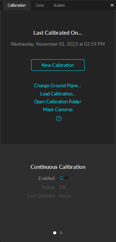
The Calibration pane is used to calibrate the capture volume for accurate tracking. This pane is typically open by default when Motive starts. It can also be opened by selecting Calibration from the View menu, or by clicking the icon.

Overview

Calibration is essential for high quality optical motion capture systems. During calibration, the system computes the position and orientation of each camera and number of distortions in captured images to construct a 3D capture volume in Motive. This is done by observing 2D images from multiple synchronized cameras and associating the position of known calibration markers from each camera through triangulation.

If there are any changes in a camera setup the system must be recalibrated to accommodate those changes. Additionally, calibration accuracy may naturally deteriorate over time due to ambient factors such as fluctuations in temperature. For this reason, we recommend recalibrating the system periodically.

This page will provide a brief overview of the options available on the Calibration Pane. For more detail on these functions and to learn more about calibration outside of the functionality of the Calibration pane, please read the page.

New Calibration

Prepare the Volume

Before you begin the calibration process, ensure the volume is properly setup for the capture.

  • Remove all extraneous reflections or markers in the volume. Cover any that cannot be removed.

When you are ready to begin calibrating, click the New Calibration button.

Masking

The first step in the system calibration process is to mask any reflections that cannot be removed from the volume or covered during calibration, such as the light from another camera.

Prime series camera indicator LED rings will light up in white if reflections are detected.

  • Check the corresponding camera view to identify where the reflection is coming from, and if possible, remove it from the capture volume or cover it for the calibration.

Clear Masks

Cancel

Cancels the calibration process and returns to the Calibration pane's initial window.

Mask

Applies masks to all detected objects in the capture volume.

Skip

This button bypasses the masking process and is not recommended.

Continue

This button will move to the next phase of the Calibration process with the masks applied.

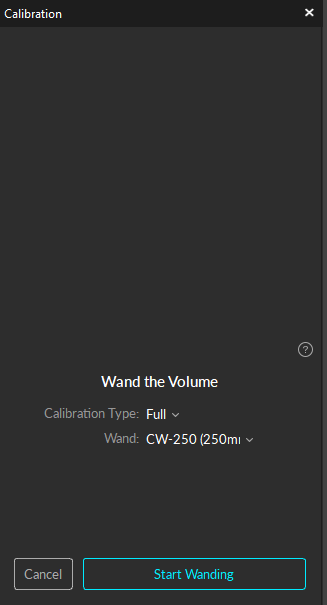
Wand the Volume

Calibration Type

  • Full: Calibrate all the cameras in the volume from scratch, discarding any prior known position of the camera group or lens distortion information. A full calibration will also take the longest time to run.

  • Refine: Adjusts slight changes in the calibration of the cameras based on prior calibrations. This will solve faster than a full calibration. Use this only if the cameras have not moved significantly since they were last calibrated. A refine calibration will allow minor modifications in camera position and orientation, which can occur naturally from the environment, such as due to mount expansion.

Refinement cannot run if a full calibration has not been completed previously on the selected cameras.

Wand

Cancel

This button moves back one step to the masking window.

Start Wanding

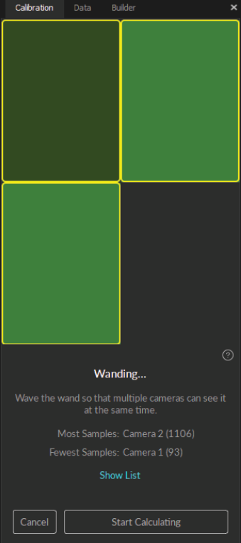
  • The Calibration pane will display a table of the wanding status to monitor the progress. For best results, wand evenly and comprehensively throughout the volume, covering both low and high elevations.

  • Continue wanding until the camera squares in the Calibration pane turn from dark green (insufficient number of samples) to light green (sufficient number of samples). Once all the squares have turned light green the Start Calculating button will become active.

  • Press Start Calculating. Generally, 1,000-4,000 samples per camera are enough. Samples above this threshold are unnecessary and can be detrimental to a calibration's accuracy.

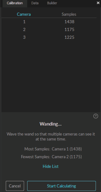
Show list

Displays the number of samples each camera has captured. Between 1,000-4,000 samples is ideal.

Start Calculating

The Start Calculating button stops the collection of samples and begins calculating the calibration based on the samples taken during the wanding stage.

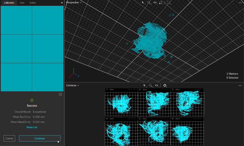
  • Camera squares will start out red, and change color based on the calibration results:

    • Red: Calibration samples are Poor and have a high Mean Ray Error.

    • Light Red: Calibration samples are fair.

    • Gray: Calibration samples are Good.

    • Dark Cyan: Calibration samples are Excellent.

    • Light Cyan: Calibration samples are Exceptional.

  • If the results are acceptable, press Continue to apply the calibration. If not, press Cancel and repeat the wanding process.

  • In general, if the results are anything less than Excellent, we recommend you adjust the camera settings and/or wanding techniques and try again.

Setting the Ground Plane

The final step in the calibration process is to set the ground plane.

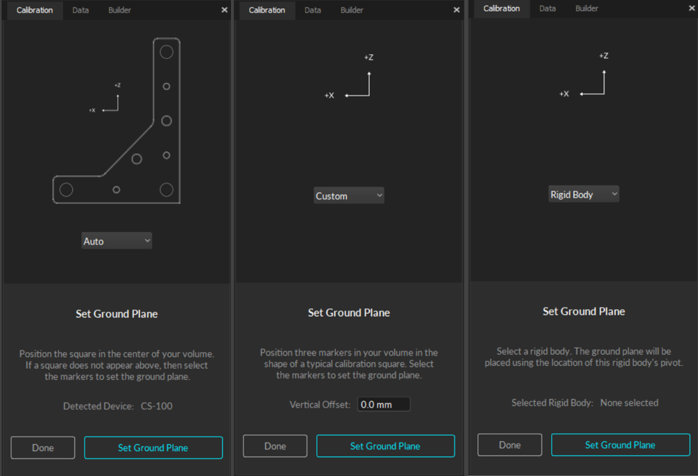
Ground Plane Selection

  • Auto (default setting): Automatically detect the ground plane once it's in the volume.

  • Custom: Create your own custom ground plane by positioning three markers that form a right-angle with one arm longer than the other, like the shape of the calibration square. Measure the distance from the midpoint of the marker to the ground and enter that value in the vertical offset field.

  • Rigid Body: Select a rigid body and set the ground plane to the rigid body's pivot point.

Once you have selected the appropriate ground plane, click Set Ground Plane to complete the calibration process.

Change Ground Plane

Refine Ground Plane

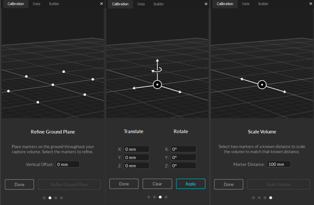
The Ground Plane Refinement feature improves the leveling of the coordinate plane. This is useful when establishing a ground plane for a large volume, because the surface may not be perfectly uniform throughout the plane.

To use this feature, place several markers with a known radius on the ground, and adjust the vertical offset value to the corresponding radius. Select these markers in Motive and press Refine Ground Plane. This will adjust the leveling of the plane using the position data from each marker.

Translate and Rotate

To adjust the position and orientation of the global origin after the capture has been taken, use the capture volume translation and rotation tool.

To apply these changes to recorded Takes, you will need to reconstruct the 3D data from the recorded 2D data after the modification has been applied.

Scale Volume

To rescale the volume, place two markers a known distance apart. Enter the distance, select the two markers in the 3D Viewport, and click Scale Volume.

Load Calibration

To load a previously completed calibration, click Load Calibration, which will open to the Calibrations folder. Select the Calibration (*.cal) file you wish to load and click OK.

Open Calibrations Folder

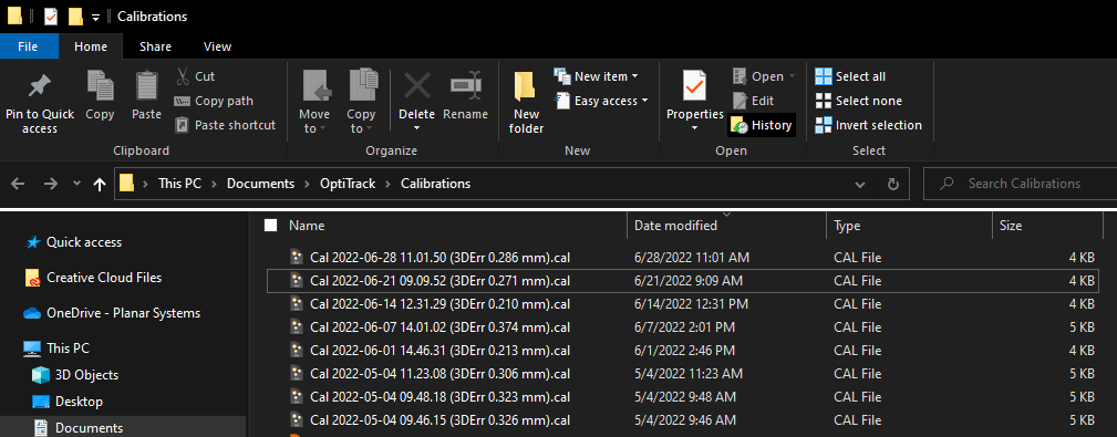
Calibration files are automatically saved in the default Calibrations folder every time a calibration is completed. Click Open Calibration Folder to manage calibration files using Windows File Explorer. Calibration files cannot be opened or loaded into Motive from this window.

Continuous Calibration

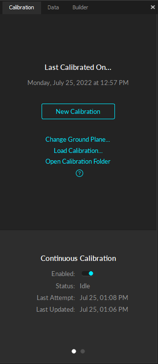
  • Status: Displays the current status of Continuous Calibration:

    • Sampling: Motive is sampling the position of at least four markers.

    • Evaluating: Motive is calculating the newly acquired samples.

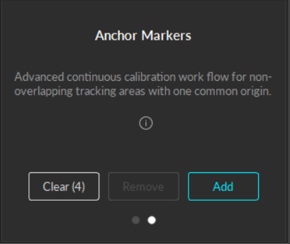
Anchor Markers

Anchor markers can be used to further improve continuous calibration updates, especially on systems that consists of multiple sets of cameras that are separated into different tracking areas, by obstructions or walls, with limited or no camera view overlap.

Place the cameras. Read more on the page.

Aim and focus the cameras. Read more on the page.

Need help? Click the button on the Calibration pane to open the documentation page.

During masking, the calibration pane will display the cameras in a grid. When a camera detects reflections in its view, a warning icon will display for that camera in the Calibration pane.

In the , click Mask to apply masks over all reflections in the view that cannot be removed or covered, such as other cameras.
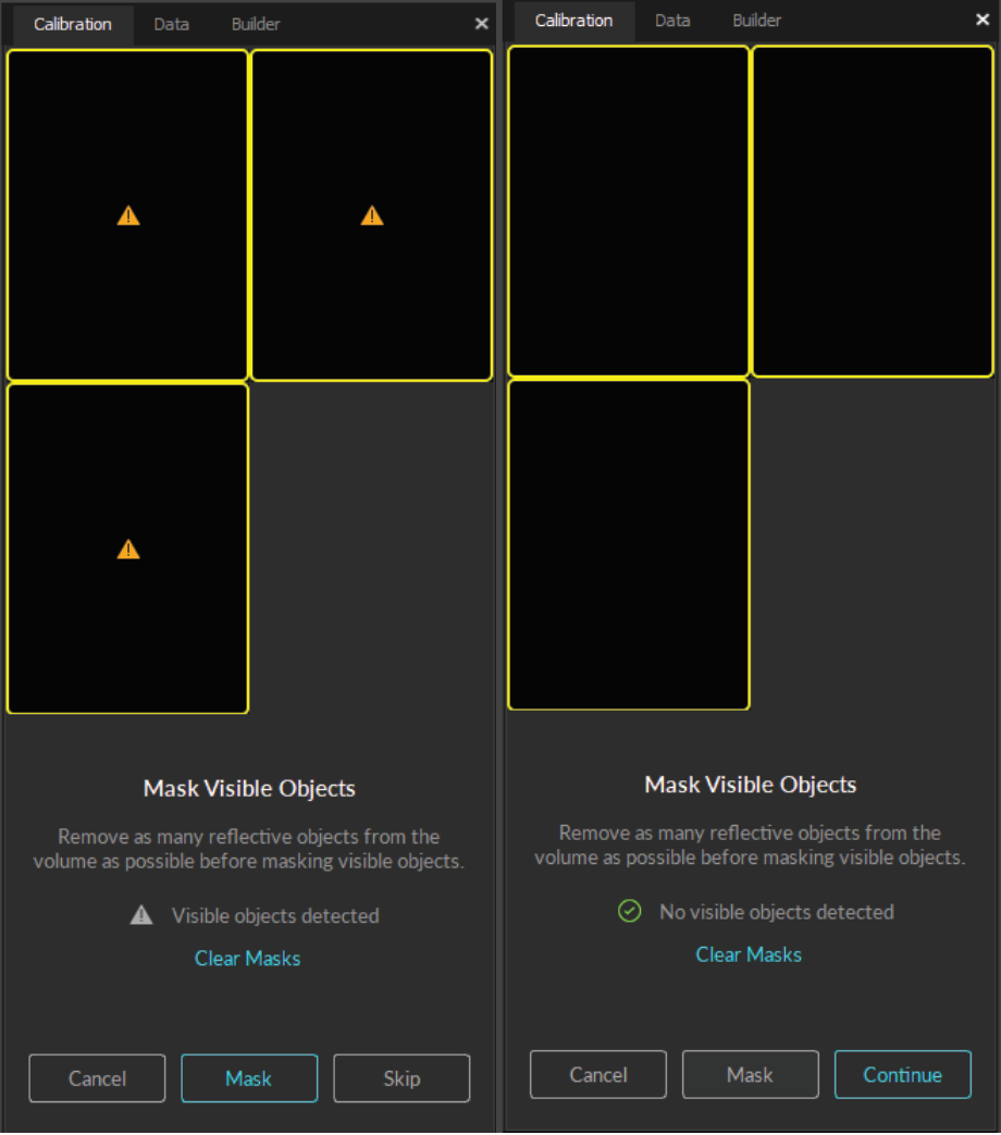
If masks were previously applied during another calibration or manually via the and they are no longer needed, click Clear Masks to remove them.

Select the wand to use to calibrate the volume. Please refer to the section on the page for more detail.

The Start Wanding button begins the calibration process. Please see in the Calibration page for more information on wanding.

On the main Calibration pane, Click Change Ground Plane... for additional tools to further refine your calibration. Use the page selector at the bottom of the pane to access the various pages.
The continuous calibration feature continuously monitors and refines the camera calibration to its best quality. When enabled, minor distortions to the camera system setup can be adjusted automatically without wanding the volume again. For detailed information, read the page.

Enabled: Turns on .

Click the right dot at the bottom of the Calibration pane to view the anchor marker window.

For more information regarding anchor markers, visit the section of the Continuous Calibration page.

Camera Placement
Aiming and Focusing
Calibration pane
Continuous Calibration
Calibration
Calibration
Calibration
Wand Types
Wanding Steps
2D viewport
Anchor Marker Setup
The Calibration pane.
Masking, Left: Visible objects detected; Right: No visible objects detected.
Camera squares changing from grey (no samples taken) to dark green (some samples taken) to light green (sufficient samples taken).
Adequate samples collected for 3 cameras.
An exceptional calibration in Motive.
Set Ground Plane options, from left: Auto, Custom, and Rigid Body.
Change Ground Plane Tools, from left: Refine Ground Plane, Translate and Rotate, and Scale Volume.
Motive's Calibrations Folder in Windows File Explorer.
Continuous Calibration status.