Settings: Views
Motive's Views Settings defined.
Last updated
Motive's Views Settings defined.
Last updated
Use the Application Settings panel to customize Motive and set default values. This page will cover the items available on the View tab. Properties are Standard unless noted otherwise.
Please see the following pages for descriptions of the settings on other tabs:
Application Settings can be accessed from the View menu or by clicking the icon on the main toolbar.
Advanced Settings
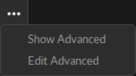
The Settings panel contains advanced settings that are hidden by default. To access these settings, click the button in the top right corner.
Use the Edit Advanced option to customize which settings are in the Advanced Settings category and which appear in the standard view, to show only the settings that are needed specifically for your capture application.
To restore all settings to their default values, select Reset Settings from the Edit menu.
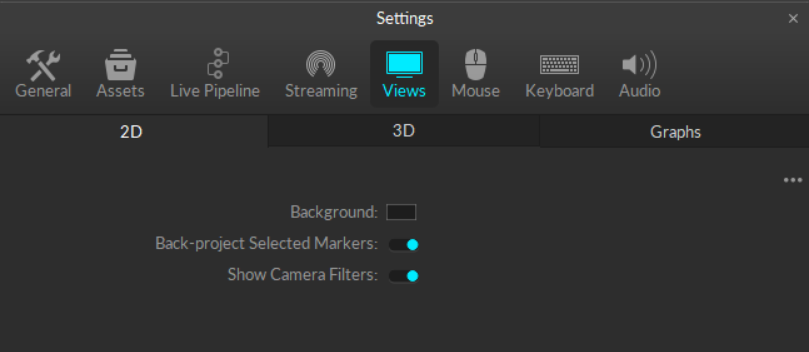
The 2D tab of the Views settings contains display settings for the Cameras View in Motive. These are all standard settings.
(Default: Black) Set the background color of the Camera View.
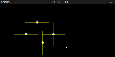
(Default: On) Display yellow crosshairs in the 2D camera view based on the calculated position of the markers selected in the 3D Perspective View.
Crosshairs that are not directly over the marker may indicate occlusion or poor camera calibration.
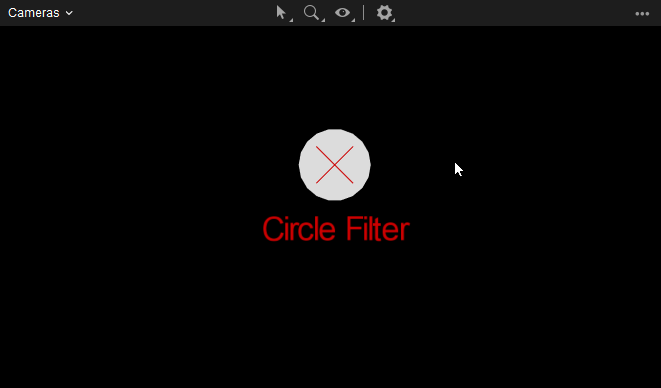
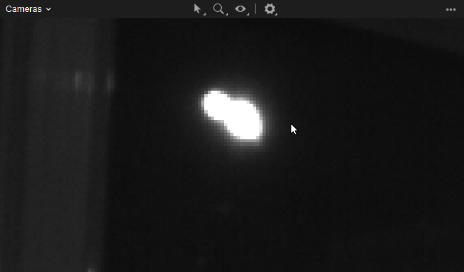
(Default: On) When enabled, the Cameras View displays a red graphic over markers filtered out by the camera's circularity and size filters. This is useful for determining why certain cameras are not tracking specific markers in the view.
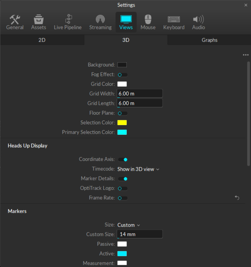
The 3D tab contains display settings for the Perspective View in Motive. Settings are Standard unless noted otherwise.
This section contains settings that control the look of the 3D Perspective View. All are standard settings.
(Default: black) Set the background color of the Perspective View.
(Default: off) Turn on a gradient “fog” effect.
(Default: white) Set the color of the ground plane grid.
(Default: 6 meters) Set the width, in meters, of the ground plane grid.
(Default: 6 meters) Set the length, in meters, of the ground plane grid.
(Default: off) Display the floor plane in the Perspective View. When disabled, only the floor grid is visible.
(Default: gray) Set the color for the floor plane. This option is only available when the Floor Plane setting is enabled.
(Default: yellow) Set the color of selected objects in the 3D Viewport. This color is applied to secondary items when multiple items are selected.
(Default: cyan) Set the color of the primary selected object in the 3D Viewport. When multiple objects are selected, the primary selection is the object that was selected last.
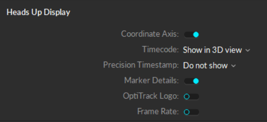
Settings in this section determine which informational overlays to include in the 3D Viewport. All settings are standard unless noted otherwise.
When using an external timecode signal through an eSync device, this setting determines where to display the timecode:
Show in 3D View: Display the timecode at the bottom of the 3D Viewport. This is the default setting.
Show in Control Deck: Display the timecode in the control deck below the 3D Viewport.
Do not Show: Hide the timecode.
Determine where to display the timecode for Precision Time Protocol (PTP) devices, if in use:
Show in 3D View: Display the PTP timecode at the bottom of the 3D Viewport.
Show in Control Deck: Display the PTP timecode in the control deck below the 3D Viewport.
Do not Show: Hide the PTP timecode. This is the default setting.
(Default: on) Show marker count details in the bottom-right corner:
Total markers tracked
Total markers selected
(Default: off) Display the OptiTrack logo in the top right corner.
(Default: off) Display the refresh rate in the top left corner.
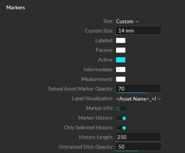
Settings in this section determine how markers are displayed in the 3D Viewport. All settings are standard unless noted otherwise.
(Default: custom) Determine whether markers are represented by the calculated size or overwritten with a set diameter (custom).
(Default: 14mm) Determines the fixed diameter of all 3D markers when the marker Size is set to Custom.
(Default: white) Set the color for labeled markers. Markers labeled using either a Rigid Body or Skeleton solve are colored according to their asset properties.
(Default: white) Set the color for passive markers. Retro-reflective markers or continuously illuminating IR LEDs are recognized as passive markers in Motive.
(Default: cyan) Set the color for active markers.
(Default: white) Set the color for active markers that have yet to be identified in Motive. The marker color will change to the Active color once the marker is identified.
To adjust the number of frames it takes for Motive to identify an active marker, go to Settings -> Live Pipeline -> Solver -> Live Pipeline Presets -> Active Pattern.
(Default: white) Set the color for measurement points created using the Measurement Probe.
The Measurement Probe is used to collect the x/y/z coordinates of a fixed point in the capture volume that is not linked to a physical marker.
(Default: 70) Set the opacity level for markers in a solved asset. Lower values reduce the brightness and color of the markers in the 3D Viewport.
Determine whether marker labels displayed in the 3D Viewport will include the Asset name (the default setting) or just the marker label name.
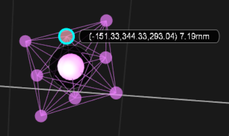
(Default: off) Display the 3D positions and estimated diameter of selected markers. If the marker label visual is also enabled, the marker info will display at the end of the label.
(Default: on) Display a trail to show the history of marker positions over time. When the marker is selected, the trail will use the color chosen in the Selection Color setting (yellow by default). The trail for unselected markers will follow the color of the marker itself.
(Default: on) When marker history is selected, this setting restricts the marker history trails to only the markers selected in the 3D Viewport.
(Default: 250) Set the number of past frames to include in the marker history.
(Default: 50) Set the opacity level for marker sticks when their markers are not being tracked. Lower values reduce the brightness and color of the sticks in the 3D Viewport.
Settings in this section determine how cameras are displayed in the 3D Viewport. All settings are standard.
(Default: teal) Set the color of tracking cameras in the 3D Perspective View. Tracking cameras are set to Object mode or Precision mode.
(Default: magenta) Set the color of reference cameras in the 3D Perspective View. Reference cameras are set to capture MJPEG grayscale videos or color videos (Prime Color series).
(Default: off) Use color to distinguish cameras by partitions rather than function.
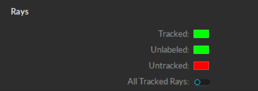
Cameras detect reflected rays of infrared light to track objects in the capture volume. Settings in this section determine how camera rays are displayed in the 3D Viewport. All settings are standard unless noted otherwise.
(Default: green) Set the color for Tracked Rays, which are rays that connect a camera to a marker.
(Default: green) Set the color for rays that are tracked but connect to unlabeled markers.
(Default: red) Set the color for untracked rays, which are rays that do not connect to a marker.
The 3D Viewport Visual Aids includes an option to view the Capture Volume. Settings in this section determine how the Capture Volume visual displays. All settings are standard.
(Default: checkered blue) Set the color used to visualize the capture volume.
(Default: 3) Set the minimum number of cameras required to form a field of view (FOV) overlap when visualizing the parameters of the capture volume.
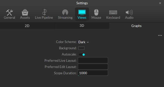
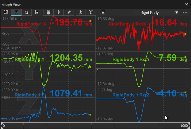
The Graphs tab under the Views settings contains display settings for the Graph Pane. These are all standard settings.
(Default: dark) Set the color to use for the plot guidelines.
(Default: black) Set the background color to use for the plots.
(Default: on) When enabled, the y-axis of each plot will autoscale to fit all the data in the view, and zoom automatically for best visualization. For fixed y-plot ranges, this setting can be disabled. See the Graph View pane page for more information.
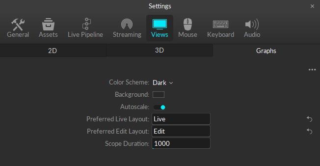
(Default: none) Preferred graph layout used for Live mode. Enter the name of the layout you wish to use exactly as it appears on the layout menu. Both System layouts and User layouts can be used.
(Default: none) Preferred graph layout used for Edit mode. Enter the name of the layout you wish to use exactly as it appears on the layout menu. Both System layouts and User layouts can be used.
Graph layouts are .xml files saved in C:\ProgramData\OptiTrack\Motive\GraphLayouts.
You can copy the .xml files to your project folders for sharing and later use. Copy them back into the GraphLayouts folder when needed to make them available in Motive.
(Default: 1000) The scope, in frames, of the domain range used for plotting graphs.
(Default: on) Display the coordinate axis in the lower left corner. This overlay can also be toggled on or off from the Visuals menu in the 3D Viewport.
This overlay can also be toggled on or off from the Visuals menu in the 3D Viewport.
(Default: off) Display all tracked rays. Additional options to display tracked rays are available from the Visual Aids Menu in the 3D Viewport. Click the button and select Tracked Rays to see more.