LogoLogo
WebsiteSupportDownloadsForumsQuick LinksContact Us
v3.3
v3.3
  • OptiTrack Documentation
  • WHAT'S NEW
    • What's New in Motive 3.3
  • QUICK START GUIDES
    • Quick Start Guide: Getting Started
    • Quick Start Guide: Prime Color Camera Setup
    • Quick Start Guide: Precision Capture
    • Quick Start Guide: Tutorial Videos
    • Quick Start Guide: Active Marker Tracking
    • Quick Start Guide: Outdoor Tracking Setup
  • HARDWARE
    • Cameras
      • Ethernet Cameras
        • PrimeX 120
        • PrimeX 41
        • PrimeX 22
        • PrimeX 13
        • PrimeX 13W
        • SlimX 13
        • Prime Color
        • VersaX 22
        • VersaX 41
        • VersaX 120
      • USB Cameras
        • Slim 3U
        • Flex 13
        • Flex 3
        • Duo 3
        • Trio 3
        • Adjusting Global Origin for Tracking Bars
    • Prepare Setup Area
    • Camera Mount Structures
    • Camera Placement
    • Ethernet Camera Network Setup
      • General Overview and Specs
      • Windows 10 Network Settings
      • Cabling and Load Balancing
      • Switch Configuration for PrimeX 120
      • NETGEAR ProSafe GSM7228S: Disabling the Broadcast Storm Control
      • White/Blacklisting Cameras
    • USB Camera System Setup
      • USB Camera Network Overview and Specs
      • Duo 3 and Trio 3 Setup
      • Tracking Bar Coordinate System
        • Transforming Coordinate System: Global to Local
    • Aiming and Focusing
    • Camera Status Indicators
  • MOTIVE
    • Installation and License Activation
    • Motive Basics
    • Calibration
      • .mcal XML Calibration Files
      • Continuous Calibration
      • Continuous Calibration (Info Pane)
      • Calibration Squares
    • Markers
    • Assets
      • Gizmo Tool: Translate, Rotate, and Scale
    • Rigid Body Tracking
      • Aligning Rigid Body Pivot Point with a Replicated 3D Model
    • Skeleton Tracking
    • Trained Markersets
    • IMU Sensor Fusion
    • Data Recording
      • Data Types
    • Labeling
    • Data Editing
    • Data Export
      • Data Export: BVH
      • Data Export: C3D
      • Data Export: CSV
      • Data Export: FBX
      • Data Export: TRC
    • Data Streaming
    • Camera Video Types
    • Audio Recording
    • Motive HotKeys
    • Measurement Probe Kit Guide
    • Motive Batch Processor
    • Reconstruction and 2D Mode
  • MOTIVE UI PANES
    • Settings
      • Settings: General
      • Settings: Assets
      • Settings: Live Pipeline
      • Settings: Streaming
      • Settings: Views
      • Settings: Mouse and Keyboard
      • Settings: Audio
    • Assets Pane
    • Builder Pane
    • Constraints Pane
      • Constraints XML Files
    • Calibration Pane
    • Data Pane
    • Devices Pane
    • Edit Tools Pane
    • Graph View Pane
    • Info Pane
    • Labels Pane
    • Log Pane
    • Probe Pane
    • Properties Pane
      • Properties Pane: Camera
      • Properties Pane: Force Plates
      • Properties Pane: NI-DAQ
      • Properties Pane: OptiHub2
      • Properties Pane: Rigid Body
      • Properties Pane: Skeleton
      • Properties Pane: Take
      • Properties Pane: Trained Markerset
      • Properties Pane: eSync2
    • Status Panel
    • Toolbar/Command Bar
    • Control Deck
    • Viewport
  • PLUGINS
    • OptiTrack Blender Plugin
      • OptiTrack Blender Plugin
    • OptiTrack Unreal Engine Plugin
      • Unreal Engine: OptiTrack Live Link Plugin
        • Quick Start Guide: Real-Time Retargeting in Unreal Engine with Live Link Content
        • Unreal Editor for Fortnite (UEFN): OptiTrack Plugin for Live Link Hub
        • Unreal Engine: Live Link Camera Stream Setup
        • Live Link Content: Active Puck Static Meshes
      • Unreal Engine: MotionBuilder Workflow
      • Unreal Engine: HMD Setup
      • Unreal Engine VCS Inputs
    • OptiTrack Unity Plugin
      • Unity: HMD Setup
    • OptiTrack OpenVR Driver
    • OptiTrack MATLAB Plugin
    • Autodesk Maya
      • Autodesk Maya: OptiTrack Insight VCS Plugin
    • Autodesk MotionBuilder
      • Autodesk MotionBuilder Plugin
      • Autodesk MotionBuilder: OptiTrack Skeleton Plugin
      • Autodesk MotionBuilder: OptiTrack Optical Plugin
      • Autodesk MotionBuilder: OptiTrack Insight VCS Plugin
      • Autodesk MotionBuilder: Timecode Data
    • OptiTrack Peripheral API
    • External Plugins
      • Houdini 19 Integration
  • ACTIVE COMPONENTS
    • Active Components Hardware
      • Active Puck
      • Wired AnchorPuck
      • CinePuck
      • Wired CinePuck
      • BaseStation
      • Information for Assembling the Active Tags
      • Manus Glove Setup
    • Configuration
      • Active Batch Programmer
      • Active Hardware Configuration: PuTTY
      • Active Component Firmware Compatibility
    • Active Marker Tracking
      • Active Finger Marker Set
  • SYNCHRONIZATION
    • Synchronization Hardware
      • External Device Sync Guide: eSync 2
      • External Device Sync Guide: OptiHub2
    • Synchronization Setup
    • OptiTrack Timecode
  • VIRTUAL PRODUCTION
    • Unreal Engine: OptiTrack InCamera VFX
    • Entertainment Marker Sets
    • PrimeX 41
  • MOVEMENT SCIENCES
    • Movement Sciences Hardware
      • General Motive Force Plate Setup
      • AMTI Force Plate Setup
      • Bertec Force Plate Setup
      • Kistler Force Plate Setup
      • Delsys EMG Setup
      • NI-DAQ Setup
      • Multiple Device Setup
    • Movement Sciences Marker Sets
      • Biomechanics Marker Sets
      • Biomech (57)
      • Rizzoli Marker Sets
    • For Visual3D Users
    • Prime Color Camera Setup
      • Prime Color Setup: Required Components
      • Prime Color Setup: Hardware Setup
      • Prime Color Camera Setup: Camera Settings
      • Prime Color Camera Setup: Prime Color FS Calibration
      • Prime Color Setup: Data Recording / Export
      • Prime Color Camera Setup: FAQ / Troubleshooting
      • Prime Color Camera Setup: Windows Network Settings
  • VIRTUAL REALITY
    • VR Plugins
      • VR Unreal Engine
        • OptiTrack Unreal Engine Plugin
        • Unreal Engine: OptiTrack Live Link Plugin
          • UE5.1 Live Link Retarget External Workaround
        • Unreal Engine VCS Inputs
      • VR Unity
        • OptiTrack Unity Plugin
      • VR OpenVR
        • OptiTrack OpenVR Driver
    • VR HMD Setup
      • Unreal Engine: HMD Setup
      • Unity: HMD Setup
      • Manually Calibrating the HMD Pivot Point
      • Sync Configuration with an HTC Vive System
    • SlimX 13
    • Active Marker Tracking
      • Active Finger Marker Set
    • Synchronization Hardware
      • External Device Sync Guide: eSync 2
      • External Device Sync Guide: OptiHub2
  • ANIMATION
    • Autodesk Maya
      • Autodesk Maya: OptiTrack Insight VCS Plugin
    • Autodesk MotionBuilder
      • Autodesk MotionBuilder Plugin
      • Autodesk MotionBuilder: OptiTrack Skeleton Plugin
      • Autodesk MotionBuilder: OptiTrack Optical Plugin
      • Autodesk MotionBuilder: OptiTrack Insight VCS Plugin
      • Autodesk MotionBuilder: Timecode Data
  • ROBOTICS
    • MoCap4ROS2 Setup
    • OptiTrack Robot Applications
    • Outdoor Tracking Setup
  • DEVELOPER TOOLS
    • Developer Tools Overview
    • Camera SDK
      • Class: cCameraModule
      • Class: cUID
    • Motive API
      • Motive API: Quick Start Guide
      • Motive API Overview
      • Motive API: Function Reference
      • Motive API Camera Calibration
    • NatNet SDK
      • NatNet 4.1
      • NatNet: Class/Function Reference
      • NatNet: Creating a Managed (C sharp) Client Application
      • NatNet: Creating a Native (C++) Client Application
      • NatNet: Data Types
      • NatNet: Matlab Wrapper
      • NatNet: Migration to NatNet 3.0 libraries
      • NatNet: Remote Requests/Commands
      • NatNet: Sample Projects
      • NatNet: Unicast Data Subscription Commands
      • Latency Measurements
    • VRPN Sample
    • Peripheral API: Glove Devices
  • SKELETON MARKER SETS
    • Full Body
      • Baseline (41)
      • Core (50)
      • Biomech (57)
      • Conventional (39)
    • Full Body + Fingers
      • Baseline + Passive Fingers (49)
      • Baseline + Active Fingers (57)
      • Core + Passive Fingers (54)
      • Core + Active Fingers (62)
    • Upper
      • Baseline Upper (25)
      • Conventional Upper (27)
    • Lower
      • Baseline Lower (20)
      • Helen Hayes Lower (19)
      • Conventional Lower (16)
    • Hand and Fingers
      • Left/Right Hand (4) Active
      • Left/Right Hand (10) Active + Passive
      • Active Finger Marker Set
    • Glove Device Setup
      • Manus Glove Setup
      • StretchSense Glove Setup
    • Rizzoli Marker Sets
    • Entertainment Marker Sets
    • Rigid Body Skeleton Marker Set
  • GENERAL TROUBLESHOOTING
    • Licensing Troubleshooting
    • Windows 11 Optimization for Realtime Applications
    • Network Troubleshooting
    • Troubleshooting Q&A
    • Running Motive on High DPI Displays
    • Firewall Settings
Powered by GitBook
On this page
  • Overview
  • Quick Start Guide
  • Mount the Wired AnchorPuck
  • Attach the LED Cables
  • Connect to the Camera Network
  • Wired AnchorPuck in Motive
  • Product Specifications
  • Active Marker LED Specifications
  • Basic Specs

Was this helpful?

Export as PDF
  1. ACTIVE COMPONENTS
  2. Active Components Hardware

Wired AnchorPuck

Quick Start Guide, specifications, and additional information for the Wired AnchorPuck.

PreviousActive PuckNextCinePuck

Was this helpful?

Overview

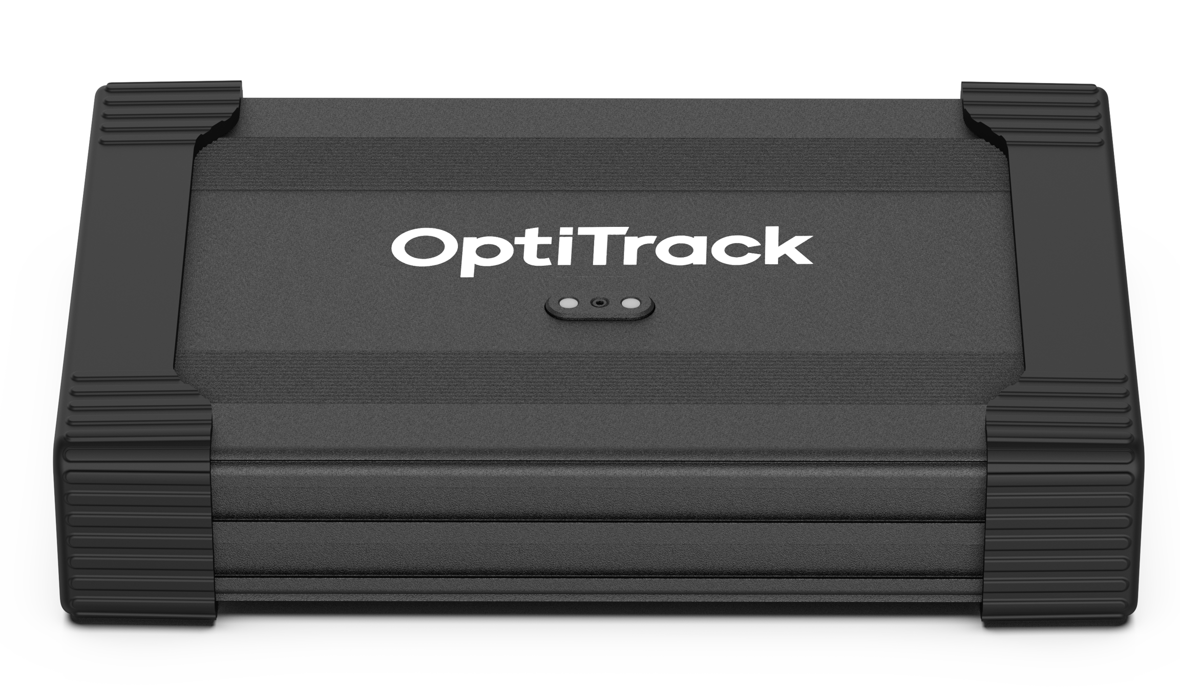
The Wired AnchorPuck is OptiTrack’s purpose-built tracking tool for Virtual Production, Studios, and Stages.
Power

Powered and connected to the camera system through a PoE+ switch, the Wired AnchorPuck is able to use higher-powered LEDs than a battery-operated Puck. Without a battery to charge, the Wired AnchorPuck is truly a set-it-and-forget-it device.

Origin

Ease of Use

The Wired AnchorPuck’s settings can be changed directly within the Motive software, without the need for the Active Batch Programmer. This allows you to quickly reconfigure the Wired AnchorPuck in place whenever needed.

Quick Start Guide

Mount the Wired AnchorPuck

The Wired AnchorPuck has five mounting options, to accommodate different environments and mounting surfaces.

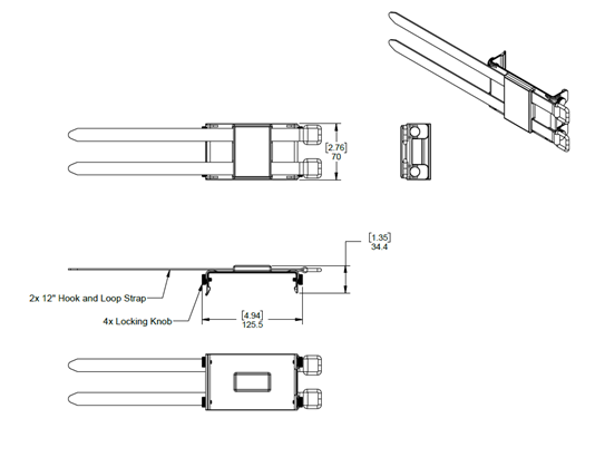
The Flat Strap mount has 2 hook and loop straps that wrap around a flat surface to which the Wired AnchorPuck is being mounted.

  • Insert the Wired AnchorPuck into the mounting panel and secure it using the 4 locking knobs.

  • Wrap the straps around the surface, pulling each strap through its loop until secured.
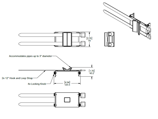
The Pipe Strap mount has 2 hook and loop straps that wrap around a round surface up to 3" in diameter, such as a pipe or speed rail.

  • Insert the Wired AnchorPuck into the mounting panel and secure it using the 4 locking knobs.

  • Position the mount with the pipe grip against the pipe.

  • Wrap the straps around the pipe, pulling each strap through its loop until secured.
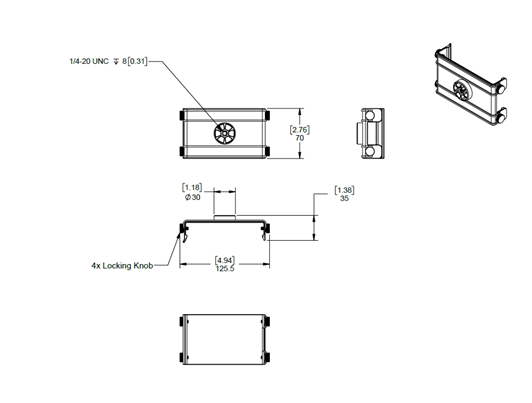
The 1/4 -20 mount attaches the Wired AnchorPuck to a 1/4-20 standard tripod mount.

  • Insert the Wired AnchorPuck into the mounting panel and secure it using the 4 locking knobs.

  • Attach the mount to the tripod.

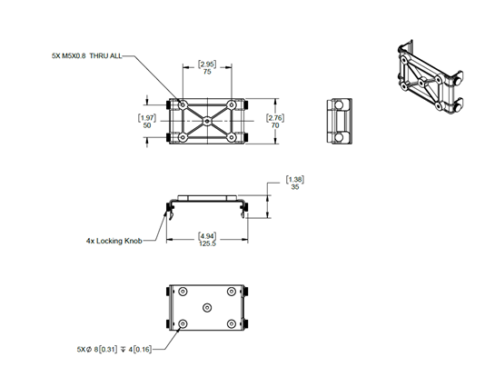
The Bolt mount attaches the Wired AnchorPuck to a surface using up to 5 M5 bolts.

  • Insert the Wired AnchorPuck into the mounting panel and secure it using the 4 locking knobs.

  • Attach the mount to the surface using M5 bolts.
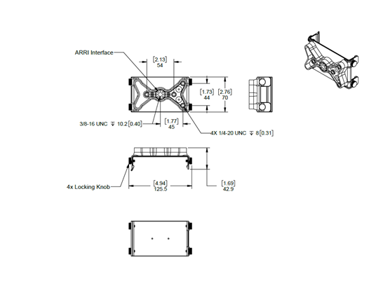
The Bolt mount attaches the Wired AnchorPuck to a surfacing using an anodized aluminum ARRI interface.

  • Insert the Wired AnchorPuck into the mounting panel and secure it using the 4 locking knobs.

  • Attach the mount to the tripod using a single ARRI connector.
Attach the LED Cables

Attach the LED cables to the ports on either side of the Wired AnchorPuck. At least 1 LED cable is required, up to 12 can be attached.

LED cables come in various lengths that can be extended with the optional Extension Cables as needed.

In some instances, you may find it more advantageous to attach the LEDs prior to mounting the puck, to ensure that all LED cables can reach the Wired AnchorPuck mounting location.

Connect to the Camera Network

Connect the Wired AnchorPuck to a PoE+ switch on the camera system network using a shielded Cat 6 or Cat 6a Ethernet cable.

Wired AnchorPuck in Motive

Product Specifications

Active Marker LED Specifications

The following specifications apply for active IR LEDs on the Wired AnchorPuck:

  • 850 nm IR spectrum

  • 12 LEDs

  • LED Output High

  • Illuminations synchronized with camera exposures

  • Optical Detection Distance: 60m as tested with a PrimeX 41 camera. Note that this may vary based on application.

Basic Specs

Wired AnchorPuck Body Dimension
  • Length: 173mm (6.81”)

  • Width: 114.5mm (4.51”)

  • Height: 36mm (1.42”)

Weight
  • 0.5Kg (1.11 lb)

Attachment

The Wired AnchorPuck has 5 optional mounting accessories, to accommodate various methods and surfaces.

  • Flat Strap Mount

  • Pipe Strap Mount

  • ¼-20 Mount

  • Bolt Mount

  • ARRI Mount

Power
  • The Wired AnchorPuck requires 22W of power through a Cat 6 or Cat 6a Ethernet cable attached to a PoE+ switch.

  • The device does not include or require a battery.

IMU
  • None

Gyroscope
  • None

With up to 12 extended markers that can be attached and placed at specific, non-changing points of reference in the volume, the Wired AnchorPuck is the perfect tool for in your capture volume.

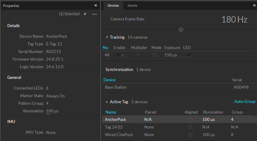
When connected to the OptiTrack system, the Wired AnchorPuck IMU is shown in the . Select it to view its properties in the Properties pane.
Please see the section , above, for more information, including technical diagrams for each mount.

Use only fully-shielded Cat 6 or Cat 6a cables. Please see the section of the page for more information on Ethernet cables and network configuration.

Devices Pane
Mount the Wired AnchorPuck
Cabling and Load Balancing
setting origin
Ethernet Cabling Requirements
A Wired AnchorPuck.
Technical diagram for the Flat Strap Mount.
Technical diagram of the Pipe Strap Mount.
Technical diagram of the 1/4 -20 Mount.
Technical diagram of the Bolt Mount.
Technical diagram of the ARRI Mount.