CinePuck
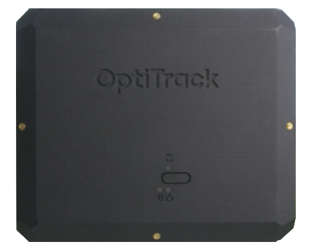
This page provides specifications and additional information for the CinePuck.
The CinePuck is designed specifically for Virtual Production or Broadcast studios. For more information on how to use the CinePuck for Virtual Production, please visit the Virtual Production section of this documentation.

Active Markers
LED Specifications
The following specifications apply for active IR LEDs on the CinePuck:
850 nm IR spectrum
8 LEDs
Illuminations synchronized with camera exposures
Illumination angle: ±60°
Basic Specs
CinePuck Body Dimensions
Dimensions
Width: 153.30mm (~6.04”)
Length: 127.68mm(~5.03”)
Height: 25.70(~1.01”)
Weight
11.58 oz (~328.29g)
Attachment
x1 ARRI-Style Anti-Twist Mount w/ 3/8"-16 threads
x6 Standard Tripod Mounts w/ 1/4"-20 threads
Battery
2200mAh Lithium polymer battery
Charging
5V micro USB Type C
~7.5 hours* of battery life (*Battery life varies depending on frame rate and exposure settings)
5hrs zero to full charge
IMU
Dimensions
Width: 15mm
Length: 15mm
Height: 5.720mm
Weight
< 1.75g
Gyroscope
Dynamic Range
500 +/- °/sec
BaseStation Load Capacity
The number of devices with IMUs (such as CinePucks) that can attach to a BaseStation is determined by the system frame rate and the divisor applied to the BaseStation. The table below shows the IMU maximum for common frame rates with a divisor rate of 1, 2, and in some cases 3.
60
26
54
83
70
22
47
71
80
19
39
62
90
16
36
54
100
14
32
49
110
13
29
44
120
11
26
40
130
10
24
140
9
22
34
150
9
20
160
8
19
30
170
7
17
180
7
16
26
190
6
15
200
6
14
23
210
5
14
220
5
13
21
230
5
12
240
4
11
18
250
4
11
As noted, the table does not include all possible frame rate and divisor combinations. If you are familiar with using Tera Term or PuTTy, you can determine the maximum number of IMUs for any specific frame rate and divisor combination not shown on the table.
Use PuTTy to change the divisor rate on the BaseStation.
Connect an IMU puck to PuTTy.
Attempt to set the ID of the puck to an unrealistically high value. This triggers a warning that includes the current number of slots available for the given frame rate.
Set the IMU puck ID to the highest available slot for the frame rate and confirm that it appears in Motive.
BaseStations have 16 radio frequency (RF) channels available for use (11-26). When adding more than one BaseStation to a system, the IMU count is simply the maximum number of IMUs multiplied by the number of BaseStations (up to 16). For example, in a system with 4 BaseStations running at 90Hz and a divisor rate of 3, the number of allowable IMUs would be 216 (54*4=216).
CinePuck in Motive
To use a CinePuck in Motive, it must first be an asset. Please see the Builder pane page for instructions on creating a rigid body asset, and the page IMU Sensor Fusion for instruction on pairing the IMU.
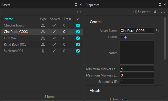
Use the Auto-Configure feature to automatically pair and align a CinePuck to its associated IMU. When auto-configured, Motive changes the name of the Rigid Body and its associated marker constraints to CinePuck_G###.
To use a different naming convention, use the Manual Pair option instead.
Once the CinePuck rigid body is created, it will be available in the Assets pane. Select the CinePuck either in the Assets pane or the 3D Viewport to display its properties in the Properties pane.

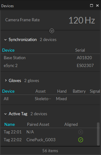
When connected to the OptiTrack system, the properties for the CinePuck IMU and its associated BaseStation are shown in the Devices Pane. Please see the Devices Pane page for more details.

Watch the video below to see a demonstration of a CinePuck setup and calibration at the 4:20 mark. Please also see our InCamera VFX page for more details.
Was this helpful?

