Properties Pane: Rigid Body
An in-depth look at the properties available for Rigid Bodies.
Rigid body properties determine how the corresponding Rigid Body asset is tracked and displayed in the 3D Viewport. This page covers the properties specific to Rigid Bodies. For general information on using and customizing the Properties pane, see the Properties Pane page. For detailed descriptions of properties for other asset types or devices, please see the following pages:
Rigid Body Properties
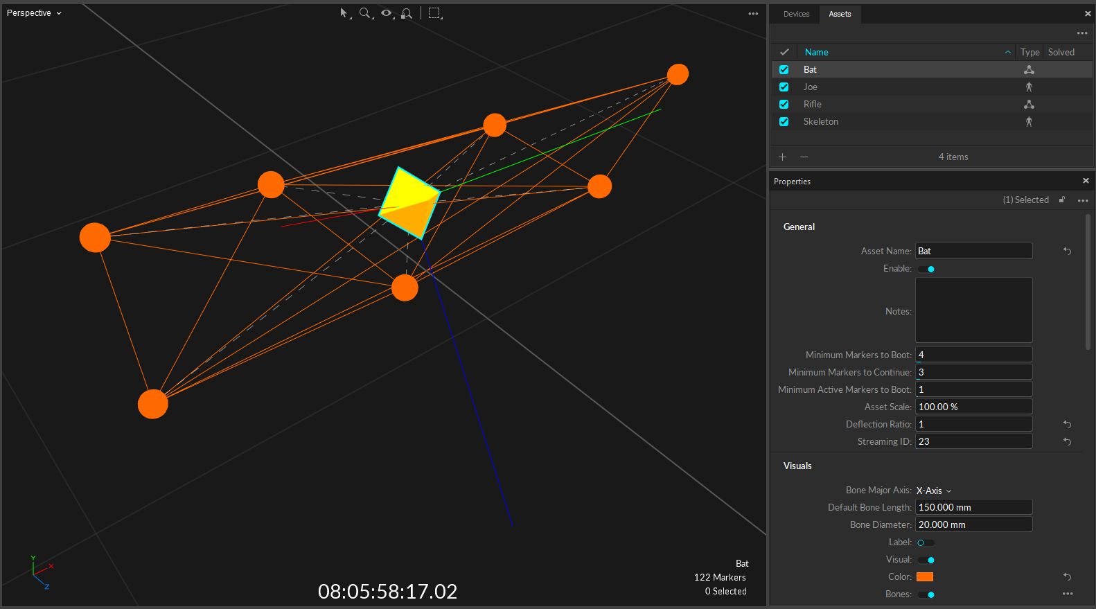
Select a Rigid Body asset in the Assets pane or in the 3D viewport, and the corresponding properties will be listed under the Properties pane. These properties can be modified both in Live and Edit mode. Default creation properties are listed under the Assets Settings.
Advanced Settings
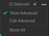
The Properties pane contains advanced settings that are hidden by default. To access these settings, click the ![]() button in the top right corner.
button in the top right corner.
Use the Edit Advanced option to customize which settings are in the Advanced Settings category and which appear in the standard view, to show only the settings that are needed specifically for your capture application.
General Properties
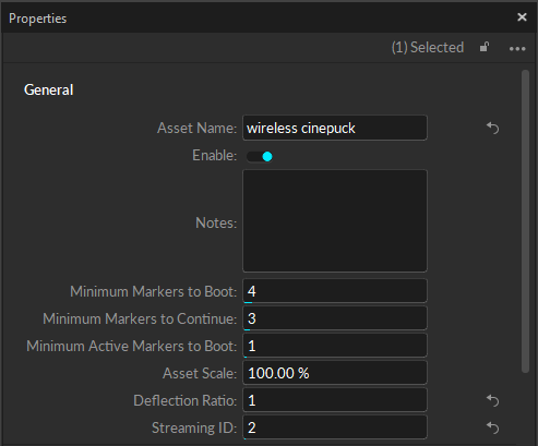
The following items are available in the General Properties section. Properties are Standard unless noted otherwise.
Asset Name
Enter a custom name for the Rigid Body. The default name is "Rigid Body X," where X is the Rigid Body ID. The Asset Name can also be changed by right-clicking the Rigid Body in the Assets pane.
Enable
Enable or Disable tracking of the selected Rigid Body. A disabled Rigid Body will not be tracked, and its data will not be included in the exported or streamed tracking data or displayed in the 3D Viewport.
To hide the markers associated with a disabled asset in the 3D Viewport:
Click
 to open the Visuals menu.
 Select Markers -> Hide for Disabled Assets.
Notes
An optional text field for storing additional information about the Rigid Body. The data in the Notes field is not included when exporting the asset to a CSV file.
Minimum Markers to Boot
Sets the minimum number of markers that must be tracked and labeled in order for a Rigid Body asset, or each Skeleton bone, to be booted or first tracked.
Minimum Markers to Continue
Sets the minimum number of markers that must be tracked and labeled in order for a Rigid Body asset, or each Skeleton bone, to continue to be tracked after the initial boot.
Minimum Active Markers to Boot (Advanced Setting)
Sets the minimum number of active markers that must be tracked and labeled for Rigid Bodies to be booted or first tracked. For more information on working with Active Markers, see the pages Active Marker Tracking and IMU Sensor Fusion.
Asset Scale (Advanced Setting)
Increase or decrease the size of the Rigid Body bone by scaling the asset. By default, the Asset Scale is set to 100%.
Deflection Ratio (Advanced Setting)
Allows the asset to deform more or less to accommodate markers that don't fit the model. High values will allow assets to fit onto markers that don't match the model as well.
Streaming ID
User definable ID for the selected Rigid Body. When working with capture data in the external pipeline, this value can be used to address specific Rigid Bodies in the scene.
Visuals
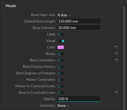
The following items are available in the Visuals section. Properties are Standard unless noted otherwise.
Bone Major Axis (Advanced Setting)
Set the axis with which the bone should be aligned. The coordinate at the end of the bone is expected to be on this axis.
Default Bone Length (Advanced Setting)
Set the offset (in mm) from the bone to the end effector, along the major axis, for bones that do not have child bones.
Bone Diameter (Advanced Setting)
Set the diameter of the bone (in mm).
Label
Display the Rigid Body name in the 3D Perspective View. When selected, a small label in the same color as the Rigid Body will appear over the centroid.
Visual
Display the marker sticks and bone constraint lines in the 3D Perspective View.
Color
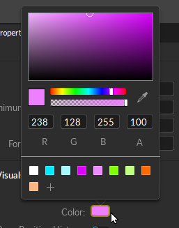
Set the color of the selected Rigid Body in the 3D Perspective View. Click the box to bring up the color picker:
Bones
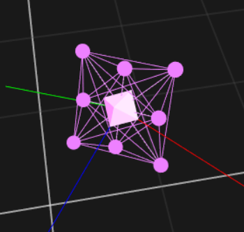
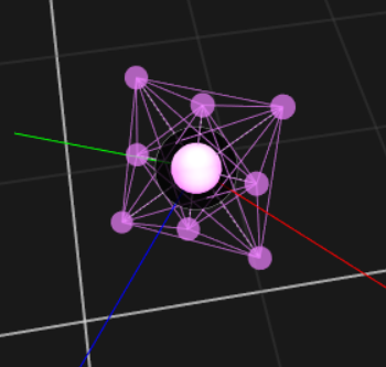
Display a visual of the bone, or pivot point, of the Rigid Body in the 3D Viewport. The shape of the bone indicates whether the asset is solved or unsolved.
Bones Color
Set the color of the bone in the 3D Perspective View. By default, the bone uses the same color as the Rigid Body asset.
Bone Orientation (Advanced Setting)
Display the Rigid Body's local coordinate axes. This option can be useful in visualizing the orientation of the Rigid Body, and for setting orientation offsets. The setting is enabled in the images above.
Bone Position History
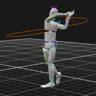
Show the history of the Rigid Body’s position in the Perspective view. When enabled, the option to set the history length becomes available.
Bone Degrees of Freedom (Advanced Setting)
Display degrees of freedom, position and orientation, for each bone pivot.
Marker Constraints
Show the Marker Constraints as transparent spheres on the Rigid Body. Marker Constraints are the expected marker locations according to the Rigid Body solve.
Marker to Constraint Lines (Advanced Setting)
Show lines between labeled Rigid Body markers and corresponding expected marker locations. This helps to visualize the offset distance between actual marker locations and the Marker Constraints.
Bone to Constraint Line (Advanced Setting)
Display a dotted line to connect each Marker Constraint to the Rigid Body bone pivot.
Opacity
Sets the opacity of an attached object. An OBJ file typically comes with a corresponding MTL file which defines its properties, and the transparency of the object is defined within these MTL files. The Opacity value under the Rigid Body properties rescales the loaded property. In other words, you can set the transparency in the MTL file and rescale it using the Opacity property in Motive.
Geometry (Advanced Setting)
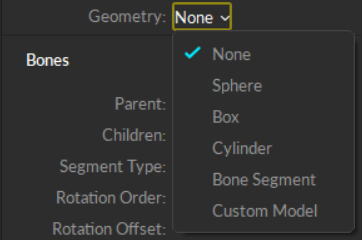
Attach a valid geometric model to the rigid body to display in the the 3D Viewport. Sphere, box, cylinder, and bone segment shapes are built-in; to use your own geometric model, select Custom Model. This will open the Attached Geometry field.
Attached Geometry
The Attached Geometry field becomes available whenever Custom Model is selected for the Rigid Body geometry.

Click the folder to the right of the field to browse to the OBJ or FBX file to replace the Rigid Body. Properties configured in the corresponding MTL files alongside the OBJ file will be loaded as well.
Geometry Settings
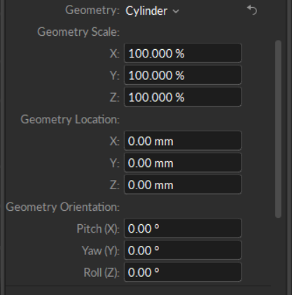
Whenever a geometric model is attached, settings to adjust the scale, location, and orientation (Pitch, Yaw, and Roll) are available.
Geometry Tips and Examples
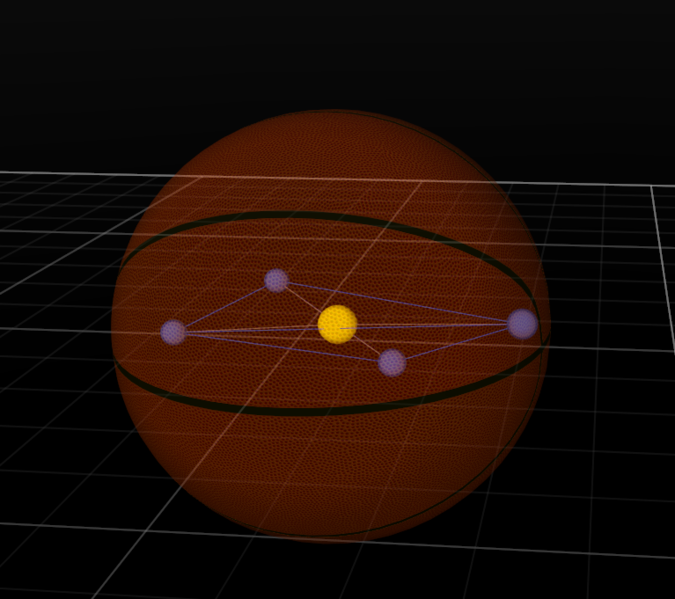
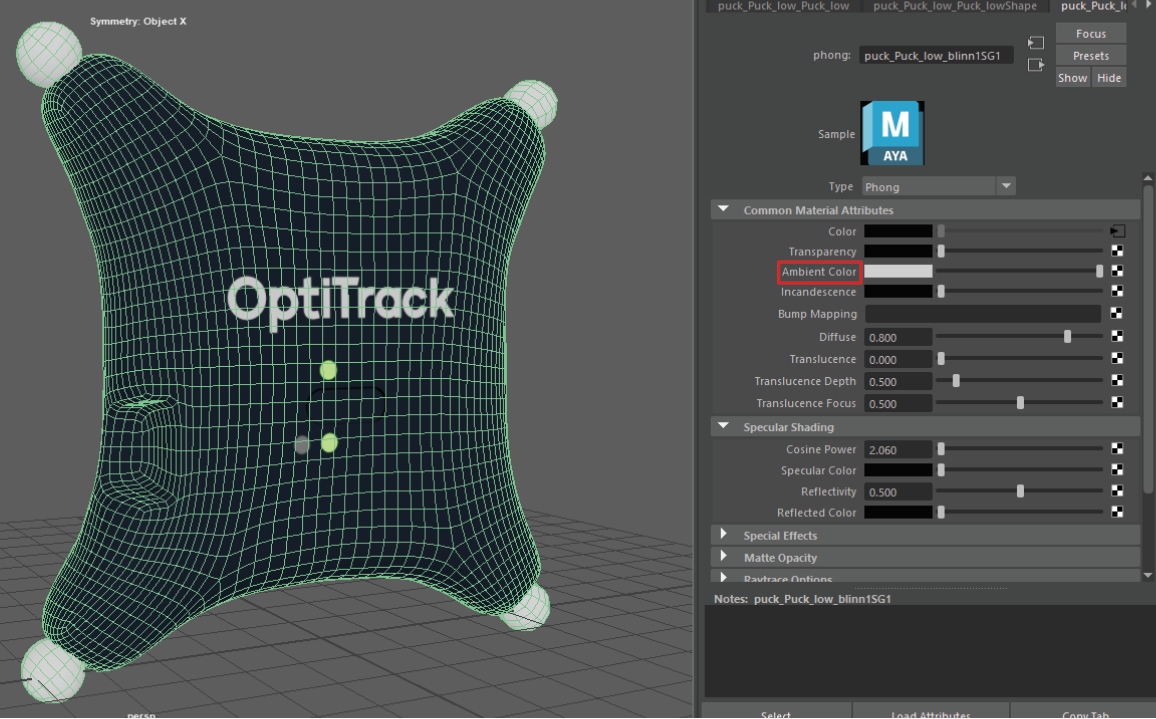
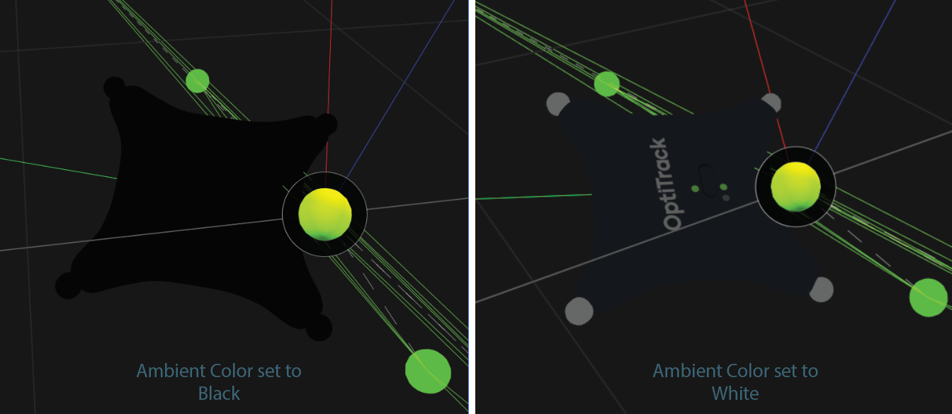
If you are exporting an OBJ file from Maya, make sure the Ambient Color setting is set to white upon export. If this color is set to black, it will remove textures when the Rigid Body is deselected.
Bones (Advanced Setting)
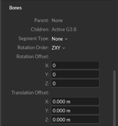
The Bone is the pivot point of a Rigid Body. Unlike Skeletons or Trained Markersets, Rigid Bodies are comprised of a single bone.
Parent
The Parent bone is the first bone in a Bone Chain, as used in Skeleton and Trained Markerset assets.
Children
A Child bone connects to the parent bone in a Bone Chain, as used in Skeleton and Trained Markerset assets. For Rigid Bodies, Motive displays one of the asset's marker labels.
Segment Type
Used for Skeleton and Trained Markerset assets to identify bone segments. For Rigid Bodies, this value is set to None.
Rotation Order
Euler angle rotation order used for calculating the bone hierarchy.
Rotation Offset
Enter values along one of the axis to reorient the Rigid Body coordinate axis.
Translation Offset
Enter values along one of the axis to move the Rigid Body pivot point.
Sensor Fusion
Active devices such as CinePucks and Pucks are often equipped with an Inertial Measurement Unit (IMU) that increases the accuracy of tracking when fused with the rigid body. Sensor Fusion properties affect how Motive corrects drift that can occur between data from the IMU and data from the active markers.
To learn more about pairing IMUs to Rigid Bodies, see the IMU Sensor Fusion page.
Sensor Fusion settings do not apply to devices (active or passive) that do not contain IMUs.
Min Alignment Count (Advanced)
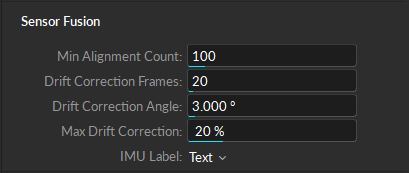
The minimum number of measurements required for the IMU to auto-align. A higher number may result in a better outcome in a suboptimal environment. For example, if the CinePuck isn't being detected as expected, adjusting this value may obtain better results.
Drift Correction Frames (Advanced)
The number of frames over which drift correction can apply.
IMUs will drift over time from their correct value without the value actually changing. Motive counters this by using the optical data as a source of truth, however optical data can be noisy and less precise than IMU data. Drift correction is the process by which the optical data is used to correct the IMU data.
Drift Correction Angle (Advanced)
Determines the angle (in degrees) between the calculated drift correction and the current drift correction that will trigger correction.
When this value is exceeded, Motive will immediately correct the sensor fusion rotation to optical. This can help in circumstances where the IMU is physically impacted, such as when it is attached to an object with recoil.
Max Drift Correction (Advanced)
The rate of drift correction.
This changes how heavily the optical data is weighted or trusted in calculating the drift correction. A drift correction of 1 will look much like the optical data, whereas a drift correction close to 0 will more closely match the IMU data.
IMU Label
Display a label with the status of the Rigid Body's IMU in the 3D Perspective View. If the asset Label is enabled, the IMU state is appended to the asset name.
None - No visual is displayed.
Text - Descriptive text provides detailed information about the IMU state.
Icon - An icon-only visual is used.
The text label includes the following information:
Tag Name.
The status of Sensor Fusion:
Rotate to Align (##/100): this status indicates that more rotations are required to align the IMU with the Rigid Body.
Fused: Sensor Fusion completed successfully.
The Optical status indicates whether the Minimum Markers to Continue threshold has been met (Optical) or not (no optical). The status Optical Good means that most of the markers can be seen and tracked.
The % status denotes the percentage of IMU packets that an IMU Tag is successfully delivering for every 100 frames.
Smoothing and Damping
Smoothing
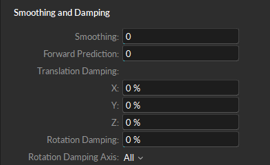
Apply double exponential smoothing to translation and rotation of the Rigid Body. Increasing this setting may help smooth out noise in the Rigid Body tracking, but excessive smoothing can introduce latency. The default value is 0 (disabled).
Forward Prediction
Compensate for system latency when tracking the corresponding Rigid Body by predicting its movement into the future. Please note that using higher values may impact the tracking stability. The default value is 0 (disabled).
Translation Damping (Advanced)
When needed, you can damp down translational tracking of a Rigid Body bone on the selected axis.
Rotation Damping (Advanced)
You can also damp down rotational tracking of a Rigid Body.
Rotation Damping Axis (Advanced)
When using Rotation Damping, select whether to apply changes to a selected axis or to all.
IMU Properties
Active devices such as CinePucks and Pucks are often equipped with an Inertial Measurement Unit (IMU) that increases the accuracy of tracking when fused with the rigid body. To learn more about pairing IMUs to Rigid Bodies, read the IMU Sensor Fusion page.
To view properties related to the IMU, select the Active Tag paired to the Rigid Body in the Devices pane.
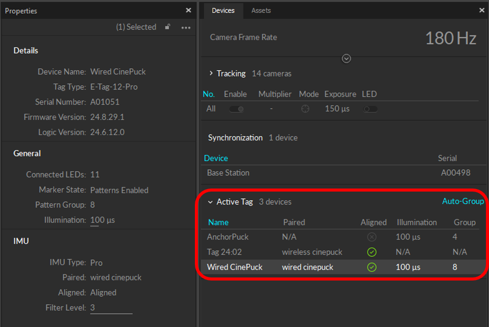
Wireless IMU properties are read-only in Motive.
Tags/Pucks ship pre-configured for every set of devices in the same order, with no Label overlap.
It's necessary to reconfigure wireless active devices when:
You have purchased new Tags/Pucks to add to a system from a previous order.
There is a need to change the RF communication channel to avoid interference.
Use the Active Batch Programmer to update these properties.
Details
Device Name
Identifies the type of device in which the IMU is installed:
An AnchorPuck is an ethernet-connected device used for continuous calibration.
A Wired CinePuck is an ethernet-connected device used for camera tracking in ICVFX .
Tag 00:00 devices are wireless active Pucks and CinePucks that connect to the camera system using a BaseStation. The first set of numbers in the tag name denotes the RF Frequency of the associated BaseStation and the second set identifies the uplink id for the device.
Tag Type
Identifies the type of tag in terms of Connection type, number of LEDs, and IMU type, if available.
E-Tag-12
E-Tag-12-Pro
Legacy IMU Tag
Serial Number
The serial number of the IMU. This value is available only for ethernet-connected IMUs.
Firmware Version (Advanced)
The Firmware version currently installed on the IMU. This value is available only for ethernet-connected IMUs.
Firmware updates should only be done at the recommendation of OptiTrack Support.
Logic Version (Advanced)
The configuration for the device's programmable logic hardware (FPGA programming). This value is available only for ethernet-connected IMUs.
General
The General IMU properties vary depending on the IMU type. For wireless devices, this section will display the BaseStation and RF Channel only.
Connected LEDs (Advanced)
The number of LED active markers on the device.
Marker State
Patterns Enabled sets the LEDs to pulse on and off according to a preset pattern.
Always On sets the LEDs to illuminate every frame.
Pattern Group
A preset collection of LED patterns that ensures a unique id for each active marker in the device. Pattern groups also make it easier to assign a different set of patterns to each device in the volume.
Pattern groups each specify 8 marker patterns. Wired pucks with more than 8 markers will occupy the selected pattern group and part of the next group.
Motive will attempt to prevent overlapping patterns with wired active tags, but can not directly read or change the pattern group values of wireless tags.
If running a wireless tag and a wired tag concurrently, confirm that the markers are in different pattern groups by selecting them in the 3D view and reading the label that appears.
Motive will also notify users when it detects duplicate active patterns in the scene.
Illumination
The amount of time, in microseconds, that each marker is lit during illumination.
BaseStation (Advanced)
The serial number of the BaseStation where the active device is connected.
This property is available only for wireless devices that connect to a BaseStation.
RF Channel
The Radio frequency communication channel used to communicate with the BaseStation for wireless devices. This is the first component of the Active Tag name in the Devices Pane.
This property is available only for wireless devices that connect to a BaseStation.
IMU
Paired
Identifies the rigid body currently paired to the IMU. Lists None if the IMU is currently unpaired.
Aligned
Displays the current state of the IMU pairing.
Unpaired
Paired
Aligned
IMU Type
Identifies the type of IMU in the device.
Legacy
Pro
Uplink ID
The Uplink ID is a number programmed to a tag that allows its paired base station to identify it uniquely from other tags. This number should be unique for each device associated with a base station. For wireless devices, the Uplink ID is the second component of the Active Tag name in the Devices Pane.
Last updated
Was this helpful?

