Properties Pane: Camera
An in-depth look at the properties available for Cameras.
Camera properties determine how and what a camera captures when recording. These settings can be configured to optimize your capture application.
This page covers the properties specific to cameras. For general information on using and customizing the Properties pane, see the Properties Pane page. For detailed descriptions of properties for various asset types or other devices, please see the following pages:
Advanced Settings
The Properties pane contains advanced settings that are hidden by default. To access these settings, click the ![]() button in the top right corner.
button in the top right corner.
Use the Edit Advanced option to customize which settings are in the Advanced Settings category and which appear in the standard view, to show only the settings that are needed specifically for your capture application.
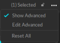
Show Properties
Select one or more cameras in either the Devices pane, the Cameras View, or the 3D Viewport to view Camera properties. When a single camera is selected, the Properties pane displays properties specific to the selection. When multiple cameras are selected, only shared values are displayed. Where the selected cameras have different values, Motive displays the text Mixed or places the toggle button in the middle position ![]() .
.
Changes made to camera settings through the Properties Pane apply to all selected cameras.
Camera Details
This section provides basic information about the selected camera(s). Properties are Standard unless noted otherwise. Most are read-only.
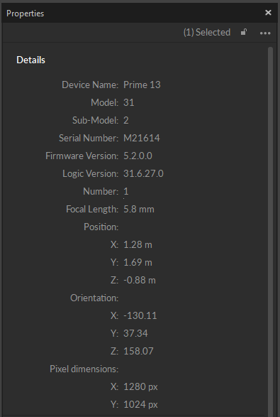
Device Name
Displays the name of the selected camera type, e.g., Prime 13, Slim 3U, etc.
Model (Advanced)
Displays the model number of the selected camera, where applicable.
Sub-Model (Advanced)
Displays the sub-model number of the selected camera, where applicable.
Serial Number
Displays the camera serial number.
Firmware Version (Advanced)
Displays the camera's firmware version.
Logic Version (Advanced)
Displays the camera's logic version. For internal Support use.
Number
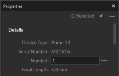
Displays the camera number assigned by Motive.
Camera numbering is determined by the Camera ID setting on the General tab of Motive's settings panel. To open up the number field for editing, set the Camera ID to Custom.
Focal Length
Displays the focal length of the camera's lens.
Position (Advanced)
Displays the x/y/z coordinates of the camera in relation to the global origin.
Orientation (Advanced)
Displays the orientation (pitch/yaw/roll) of the camera in relation to the global origin.
Pixel Dimensions (Advanced)
Displays the resolution of the camera's image sensor, in pixels.
General Settings
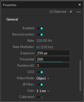
The following items are available in the General Properties section. Properties are Standard unless noted otherwise.
Enabled
A camera must be enabled to record data and contribute to the reconstruction of 3D data, if recording in object mode. Disable a camera if you do not want it included in the data capture.
Reconstruction
This setting determines whether the selected camera contributes to the real-time reconstruction of the 3D data.
When this setting is disabled, Motive continues to record the camera's 2D frames into the capture file, they are just not processed in the real-time reconstruction. A post-processing reconstruction pipeline allows you to obtain fully contributed 3D data in Edit mode.
For most applications, it's fine to have all cameras contribute to the 3D reconstruction engine. In a system with a high camera-count, this can slow down the real-time processing of the point cloud solve and result in dropped frames. Resolve this by disabling some cameras from real-time reconstruction and using the collected 2D data later in post-processing.
Rate
Shows the frame rate of the camera. The camera frame rate can be changed from the Devices pane.
Frame Rates and Windowing
Each camera model has a native frame rate, which is the maximum frame rate that will provide the highest resolution and largest field of view (FOV). When a camera runs above its native frame rate, the resolution and FOV are reduced, resulting in a smaller image. This allows the camera to keep up with the higher frame rate.
See the specifications page for the selected camera model for more detail.
Rate Multiplier
Shows the rate multiplier or divider applied to the master frame rate. The master frame rate depends on the sync configuration.
Exposure
Sets the amount of time that the camera exposes per frame in microseconds. The minimum and maximum values allowed depend on both the type of camera and the frame rate.
Higher exposure allows more light in, creating a brighter image that can increase visibility for small and dim markers. However, setting the exposure too high can introduce false markers, larger marker blooms, and marker blurring, all of which can negatively impact marker data quality.
Prior to Motive 3.2, exposure value was measured in scanlines for tracking bars and Flex3 series cameras.
Threshold
Defines the minimum brightness for a pixel to be recognized by a camera, with all pixels below the threshold ignored.
Increasing the threshold can help filter interference by non-markers (e.g. reflections and external light sources), while lowering the threshold can allow dimmer markers to be seen by the system (e.g. smaller markers at longer distances from the camera).
Threshold is an important setting while using Duplex mode, because MJPEG usually works best with brighter images while object mode does best using dark images with hotspots. For cameras in Duplex mode, we recommend setting the threshold around 220-255.
Partition ID (Advanced)
Camera partitions create the ability to have several capture volumes (multi-room) tied to a single system. Continuous Calibration collects samples from each partition and calibrates the entire system even when there is no camera overlap between spaces.
LED
This setting enables the IR LED ring on the selected camera. To track passive retro-reflective markers, this setting must be set to true (enabled) to illuminate the IR LED rings for tracking.
If the IR illumination is too bright for the capture, decrease the camera exposure setting to decrease the amount of light received by the imager, dimming the captured frames.
Video Mode
Select from the following video types:
Tracking: Tracking modes capture the 2D marker data used in the reconstruction of 3D data.
Object mode: Performs on-camera detection of centroid location, size, and roundness of the markers, and sends respective 2D object metrics to Motive to calculate the 3D data. Recommended as the default mode for recording.
Precision mode: Performs on-camera detection of marker reflections and their centroids and sends the respective data to Motive to determine the precise centroid location. Precision mode is more processing intensive than Object mode.
Reference Modes: Reference modes capture grayscale video as a visual aid during the take. Cameras in these modes do not contribute to the reconstruction of 3D data.
Grayscale: Raw grayscale is intended for aiming and monitoring the camera views and diagnosing tracking problems and includes aiming crosshairs by default. Grayscale video cannot be exported.
MJPEG: A reference mode that captures grayscale frames, compressed on-camera for scalable reference videos. MJPEG videos can be exported along with overlay information such as markers, rigid bodies, and skeleton data.
Duplex Mode: Duplex mode captures in both Object and MJPEG mode, providing reference video and tracking data from the same camera. Duplex mode unlocks more reference viewpoints when needed and supports post production markerless workflows.
Duplex mode is available in the following cameras:
PrimeX 22, 41, and 120
SlimX 22, 41, and 120
VersaX 22, 41, and 120
Duplex mode is available with the Motive:Body and Motive:Body-Unlimited licenses only.
MJPEG Quality
For cameras in MJPEG or Duplex mode, this indicates the quality of the video recording. This property is only visible when an applicable video mode is selected.
IR Filter
Sets the camera to view either visible or IR spectrum light on cameras equipped with a Filter Switcher. When enabled, the camera captures in IR spectrum, and when disabled, the camera captures in the visible spectrum.
Infrared Spectrum should be selected when the camera is being used for marker tracking applications. Visible Spectrum can optionally be selected for full frame video applications, where external, visible spectrum lighting will be used to illuminate the environment instead of the camera’s IR LEDs. Common applications include reference video and external calibration methods that use images projected in the visible spectrum.
Gain
Sets the imager gain level for the selected camera. Gain settings can be adjusted to amplify or diminish the brightness of the image.
This setting can be beneficial when tracking at long ranges. However, note that increasing the gain level will also increase the noise in the image data and may introduce false reconstructions.
Before changing the gain level, we recommend adjusting other camera settings first to optimize image clarity, such as increasing exposure and decreasing the lens f-stop.
Calibrated (Advanced)
Shows whether the selected camera has been calibrated. This property does not indicate the quality of the calibration.
Display
Show Field of View
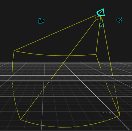
When enabled, the estimated field of view (FOV) of the selected camera is shown in the perspective viewport. When the camera is selected, the lines display in yellow. When the camera is not selected, the lines display in cyan.
Show Frame Delivery Info
Frame delivery information is used to determine how fast a camera is delivering its frame packets. When enabled, the frame delivery information is shown in the Camera views.
This setting can also be enabled by right-clicking a camera in the Cameras view or in the 3D Viewport and selecting Frame Delivery Visual.
Aiming Crosshairs are controlled globally through Motive's general settings. To see and change those settings:
Click
 to open the Settings panel.
 In the Aim Assist section of the General tab, select a value for Aiming Crosshairs:
None
Grayscale Only (default)
All Modes
2D Display Options
Properties specific to cameras that support Duplex mode.

Duplex Object Color
Set the color to use to display detected objects when in Duplex mode.
Prime Color Camera Properties
Prime color cameras also have the following additional properties that can be configured:
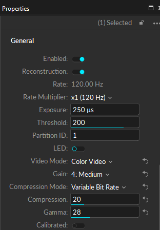
Resolution
Default: 1920 x 1080
This property sets the resolution of the images captured by the selected camera.
You may need to reduce the maximum frame rate to accommodate the additional data produced by recording at higher resolutions. The table below shows the maximum allowed frame rates for each respective resolution setting.
960 x 540 (540p)
500 FPS
1280 x 720 (720p)
360 FPS
1920 x 1080 (1080p)
250 FPS
Compression Mode
Default: Constant Bit Rate.
This property determines how much the captured images will be compressed.
Constant Bit-Rate
In the Constant Bit-Rate mode, Prime Color cameras vary the degree of image compression to match the data transmission rate given under the Bit Rate settings. At a higher bit-rate setting, the captured image will be compressed less. At a lower bit-rate setting, the captured image will be compressed more to meet the given data transfer rate. Compression artifacts may be introduced if it is set too low.
The Constant Bit-Rate mode is used by default and recommended because it is easier to control the data transfer rate and efficiently utilizes the available network bandwidth.
Variable Bit-Rate
The Variable Bit-Rate setting keeps the amount of the compression constant and allows the data transfer rate to vary. This mode is beneficial when capturing images with objects that have detailed textures because it keeps the amount of compression consistent on all frames. However, this mode may also cause dropped frames if the camera needs to compress highly detailed images, spiking the data transfer rate, which may overflow the network bandwidth as a result. For this reason, we recommend using the Constant Bit-Rate setting in most applications.
Compression
The compression property sets the percentage (100%) of the maximum data transmission speed to allocate for the camera.
Bit Rate
Default: 100 MB/s
Available only while using Constant Bit-rate Mode
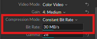
The bit-rate setting determines the selected color camera's output transmission rate.
The maximum data transmission speed that a Prime color camera can output is 100 megabytes per second (MB/s). At this setting, the camera will capture the best quality image, however, it could overload the network if there isn't enough bandwidth to handle the transmitted data.
Since the bit-rate controls the rate of data each color camera outputs, this is one of the most important settings to adjust when configuring the system.
When a system is experiencing 2D frame drops, one of the following system requirements is not being met:
Network bandwidth
CPU processing speed
RAM/disk memory
Decreasing the bit-rate in such cases may slow the data transmission speed of the color camera enough to resolve the problem.
Bit Rate and Image Quality
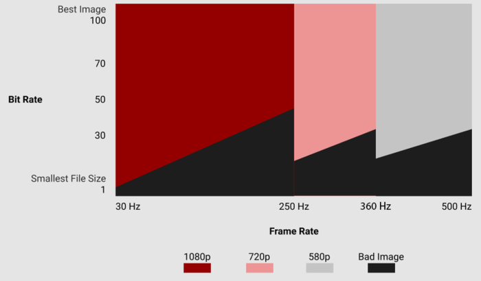
While the image quality increases at a higher bit-rate setting, this also results in larger file sizes and possible frame drops due to data bandwidth bottlenecks. The desired result may differ depending on the capture application and its intended use. The below graph illustrates how the image quality varies depending on the camera frame rate and bit-rate settings.
Tip: Monitoring data output from each camera
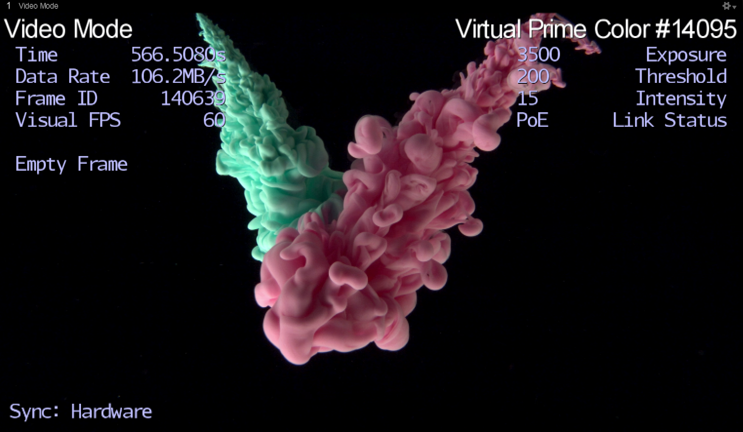
Data output from the entire camera system can be monitored through the Status Panel. Output from individual cameras can be monitored from the 2D Camera Preview pane when the Camera Info display is enabled under the visual aids ( ![]() ) option.
) option.
Gamma
Default : 24
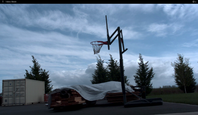
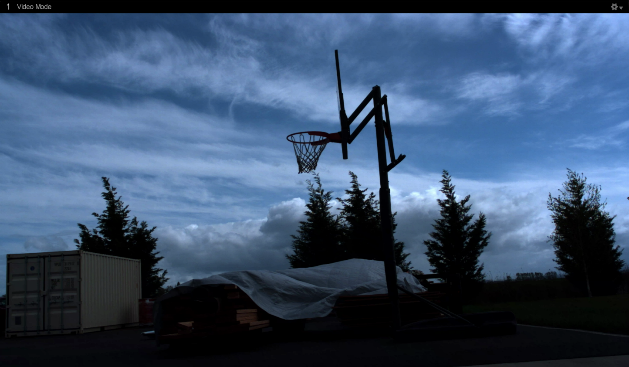
Gamma correction is a non-linear amplification of the output image. The gamma setting will adjust the brightness of dark pixels, mid-tone pixels, and bright pixels differently, affecting both brightness and contrast of the image. Depending on the capture environment, especially with a dark background, you may need to adjust the gamma setting to get best quality images.
Last updated
Was this helpful?

