Control Deck
An in-depth look at the features and functions available on the Control Deck.
Overview
Motive has two modes: Live and Edit. The Control Deck contains the operations for recording or playback, depending on which mode is active. Toggle between the two by selecting one from the ![]() button on the Control Deck or by using the Shift + ~ hotkey.
button on the Control Deck or by using the Shift + ~ hotkey.
Tip: Prime series cameras will illuminate in blue when in live mode, in green when recording, and are turned off in edit mode. See more at Camera Status Indicators.
Live Mode
Live mode is used when recording new Takes or when streaming a live capture. In this mode, all enabled cameras continuously capture 2D images and reconstruct the detected reflections into 3D data in real-time.

Live/Edit Mode
Use the Live/Edit button to switch between Live and Edit modes. When in Live mode, the Perspective View of the 3D Viewport will display the capture volume.
Take Name
Recorded captures are known as Takes in Motive, and are saved with the file extension .tak. The Take Name is an editable field that populates by default as Take <date & time> when Motive is first launched or if the field is left blank.
Session Folders in Live
The Take file is saved in the Session Folder currently open. If there is no Session Folder open or the Persistent Data Folders setting has been disabled, the Take will be saved in the Default file location: C:\Users\<user_name>\Documents\OptiTrack\Default.
Read more about Session Folders and Take management on the Data Pane page.
When switching from Edit to Live mode, the default Take Name depends on the name of the Take currently open in Edit mode.
If the current file has a default name then the new file will also use the default.
If the current file has a unique name, the new file will use the same name, adding a Take Suffix. The default suffix adds an underscore as a separator followed by three digits, including leading zeroes, e.g., My Take_001, incrementing up from the highest number of the Takes with the same name.
To Change the default Take Suffix, click the ![]() button to open the Application Settings panel. Go to the General tab -> General Section -> Take Suffix.
button to open the Application Settings panel. Go to the General tab -> General Section -> Take Suffix.
Timecode
Timecode displays the recording time and subframe in the format H:MM:SS:### where # is the recorded subframe number. The number of subframes per second is equal to the camera frame rate.
External Timecode Display Options
When using an external timecode signal through an eSync device, you can display the timecode signal here in the Control Deck or at the bottom of the 3D Viewport (the default setting).
To update, click the ![]() button to open the Application Settings panel. Go to the Views tab -> 3D -> Heads Up Display -> Timecode. Options are:
button to open the Application Settings panel. Go to the Views tab -> 3D -> Heads Up Display -> Timecode. Options are:
Show in 3D View
Show in Control Deck
Do not Show
Frame Counter
Displays the current frame number during recording.
Record / Stop
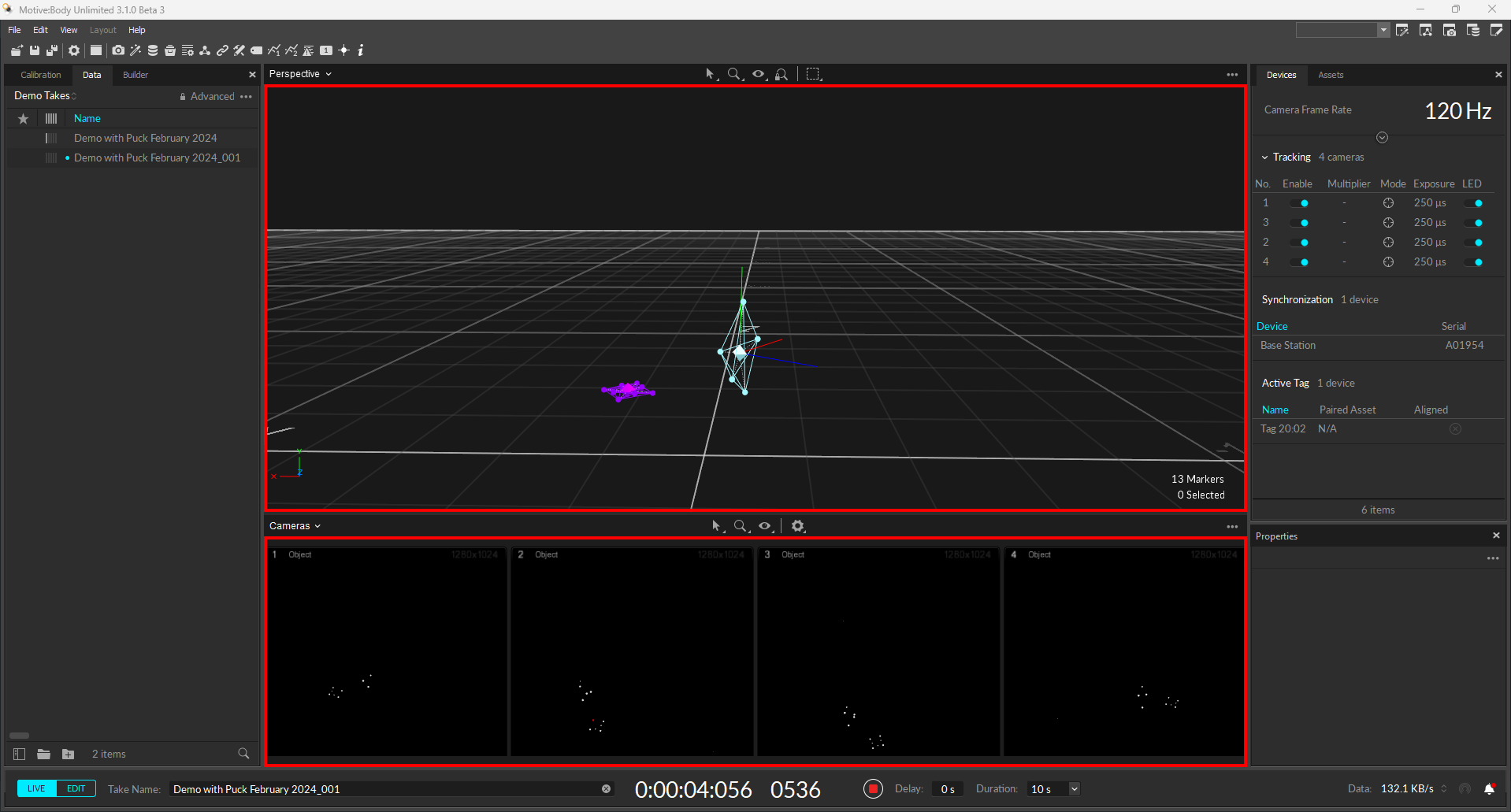
When you are ready to begin recording, click the Record button. While recording, a red outline visual displays around the Viewport panes and the Record button becomes a Stop Recording button: ![]()
Recording Delay
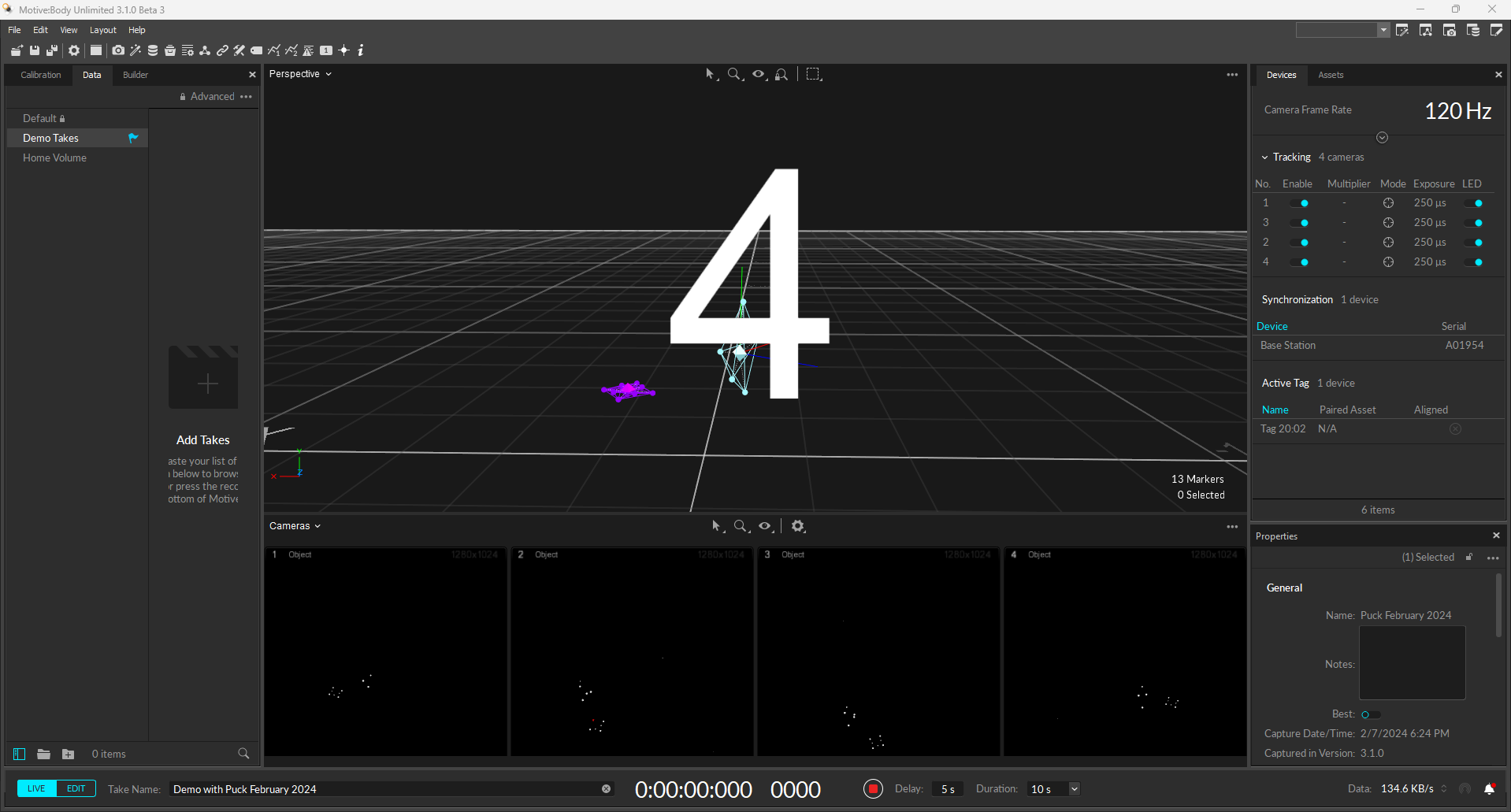
The Recording Delay feature adds a countdown before the start of the capture, allowing time to set the scene and ensure all actors are in place.
Recording Duration
Click to select one of the pre-set recording duration times (up to 60 seconds) or set to Manual to control the length of the take.
Edit Mode
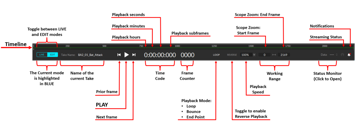
Edit Mode is used for playback of captured Take files. In this mode, you can playback and stream recorded data and complete post-processing tasks.
The Cameras View displays the recorded 2D data while the 3D Viewport represents either recorded or real-time processed data as described below.
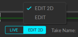
There are two modes for editing:
Edit: Playback in standard Edit mode displays and streams the processed 3D data saved in the recorded Take. Changes made to settings and assets are not reflected in the Viewport until the Take is reprocessed.
Edit 2D: Playback in Edit 2D mode performs a live reconstruction of the 3D data, immediately reflecting changes made to settings or assets. These changes are displayed in real-time but are not saved into the recording until the Take is reprocessed and saved. To playback in 2D mode, click the Edit button and select Edit 2D.
Regardless of the selected Edit mode, you must reprocess the Take to create new 3D data based on the modifications made.
Please see the Data Editing page for more information about editing Takes.
Take Name
Displays the name of the current Take.
Playback Controls
Use the playback controls to play the Take at regular speed or to move one frame at a time, forward or back.
Timecode
Timecode displays the recording time and subframe in the format H:MM:SS:### where # is the recorded subframe number. The number of subframes per second is equal to the camera frame rate.
Frame Counter
Displays the current frame number during playback.
Playback Mode
There are three modes for playback:
Loop: replays the selected range from the start until stopped manually. This is the default mode.
Bounce: playback reverses direction when it reaches either the end or start of the selected range, continuing to alternate directions until stopped manually.
End Point: playback stops when the selected range reaches the end.
Reverse Playback
Click REVERSE to playback the selected range in reverse. Unlike the Bounce playback mode, this setting maintains the reverse direction until turned off and is used with the Loop and End Point playback modes.
Playback Speed
Increase the playback speed or use a preset reduced rate (ranging from 5% to 50%) to slow it down.
View Range
The View Range fields show the Starting Frame and the Ending Frame numbers for the range selected for playback. The View Range is also known as the Working Range as it can be used to facilitate post-processing by restricting playback to the specific section being edited.
When the entire Take is selected (as in the Edit Mode image, above) the Start Frame will show 0, and the End Frame will show the final frame of the Take. If a specific range is selected, the View Range will display the Starting Frame and the Ending Frame numbers of that Working Range.

You can also use the View Range fields to manually enter the desired Working Range.
Timeline Controls
In Edit mode, the Timeline is displayed across the top of the Control Deck.

The Scrubber is a vertical white bar that shows the location of the current frame. Drag the scrubber left or right to move to a different frame.
The Working Range is a horizontal green line with vertical handles for the Starting and Ending frames. Click and drag the handles to adjust the range.
The selected frame range on a graph is shaded in yellow, with 2 yellow vertical lines to define the Starting and Ending frames. Read the Graph View Pane page for more information about working with graph data.
Status Monitor

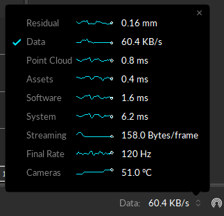
Located on the right corner of the control deck, the status monitor displays specific operational parameters in Motive.
Click the monitor to see all monitored data. The blue check mark in the leftmost column indicates the status that displays on the control deck when the monitor window is closed. To select a different status to display, click the column to the left of the status name to move the check mark.
Residual
This is the average of residual values of all live-reconstructed 3D points. This is available only in Live mode or in 2D Edit mode.
Data
The current incoming data transfer rate (KB/s) for all attached cameras.
Point Cloud
The measured latency of the point cloud reconstruction engine.
Assets
The measured latency of the rigid body solver and the skeleton solver combined.
Software
The measured software latency. This represents the amount of time it takes Motive to process each frame of captured data. This includes reconstructing the 2D data into 3D data, labeling and modeling the trackable assets, displaying in the viewport, and other processes configured in Motive.
System
Available only on Ethernet Camera systems (Prime series and Slim13E). The measured total system latency. This is the time measured from the middle of the camera exposures until Motive has fully solved all of the tracking data.
Streaming
The data rate at which the tracking data is streamed to connected client applications.
Final Rate
The final data acquisition rate of the system.
Cameras
Available only on Ethernet Camera systems (Prime series or Slim 13E). The average temperature, in Celsius, on the imager boards of the cameras in the system.
Streaming Status
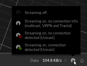
Streaming status is available only for Unicast streaming. This status is disabled for Multicast streaming.
Hover over the icon to see streaming connection status messages.
Click the icon to quickly access the Data Streaming settings.
Notifications
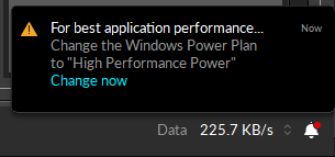
Important software notifications are reported at the right corner of the control deck. Click on the ![]() button to view the messages.
button to view the messages.
Only important configuration notifications are reported here. Software status messages are reported on the Log pane.
Was this helpful?

