Properties Pane: Force Plates
Overview
This page covers the properties specific to Force Plates. For general information on using and customizing the Properties pane, see the Properties Pane page. For detailed descriptions of properties for various asset types or other devices, please see the following pages:
Force Plate Setup
Follow the manufacturer's instructions to setup the force plate and install the software required to operate it on the Motive PC. This software must be installed before the force plate can be used in Motive.
For detailed information, please see the following force plate setup pages:
Connecting Multiple Force Plates
When connecting more than one force plate, use devices from the same manufacturer for the plates to work together properly. Collectively, the connected force plates are known as the Force Plate Group.
Force Plate Properties
Select a force plate in the Devices pane or in the 3D viewport, and the corresponding properties will be listed under the Properties pane. These properties can be modified only in Live mode.
Advanced Settings
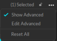
The Properties pane contains advanced settings that are hidden by default. To access these settings, click the ![]() button in the top right corner.
button in the top right corner.
Use the Edit Advanced option to customize which settings are in the Advanced Settings category and which appear in the standard view, to show only the settings that are needed specifically for your capture application.
Force Plate Group Policy
Group policy requires certain properties to be identical on all devices in the force plate group. Shared settings include:
Enabled status
Sampling rates
Sync modes
These settings must have the same values for all force plates in the group.
If you need to disable a specific force plate in the group, power off its amplifier or disable the device through Windows Device Manager.
Settings
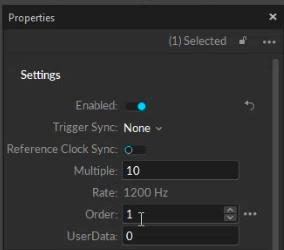
The following items are available in the Settings section. All of these are standard properties.
Enabled
Enables the selected force plate. Only enabled force plates are shown in Motive and used for data collection.
Triggered Sync
Select whether the force plate is synchronized through a recording trigger. This must be set to Device when force plates are synchronized through recording trigger signal from the eSync2. This must be set to None when synchronizing through a clock signal.
Reference Clock Sync
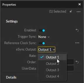
Enables the force plate system to synchronize to an external clock signal, the eSync2. When this setting is enabled, the eSync Output setting becomes available.
eSync Output
Select the output port that the force plate amplifier is connected to on the eSync2. This setting is only visible when Reference Clock Sync is enabled.
Multiple
This sets the multiplier applied to the camera system frame rate. This setting is only available when using triggered sync and can also be configured from the Devices pane. The resulting rate determines the sampling rate of the force plates.
Rate
The resulting data acquisition rate of the force plates, based on the camera frame rate set in the Devices pane and the multiplier property set above, when using triggered sync. For reference clock sync configurations, this will match the frequency of the clock signal. For triggered sync setups, this will be the product of the Multiple value (above) and the camera system frame rate.
Order
The assigned number of the force plate.
User Data
A text field available to input user-specified information.
Details
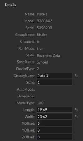
The following items are available in the Details section. Properties are Standard unless noted otherwise.
*Values for properties noted with an asterisk (*) are derived from the force plate manufacturer's software.
Name (Advanced)*
The name of the selected force plate.
Model*
The model number of the force plate.
Serial*
The force plate serial number.
Group Name*
The force plate group name, typically the name of the manufacturer.
Channels (Advanced)
The number of active channels available in the selected device. For force plates, this defaults to 6, with channels responsible for measuring 3-dimensional force and moment data.
Run Mode / Sync Mode (Advanced)
The Mode property varies depending on whether Motive is in Live or Edit mode. When Live, the property will display Run Mode Live. When in edit mode, the property Sync Mode displays either a 1 if the device was set to use a trigger sync, and a 0 if it was not synced or it was set to a reference clock.
State
Indicates the state that the force plate is in. If the force plate is streaming data, the state is Receiving Data. If the force plate is on standby for data collection, the state is Ready.
SyncStatus
Current status of the force plate synchronization: need sync, ready for sync, or sync.
DeviceType (Advanced)
A numeric value (2) assigned by Motive to identify the device as a force plate.
DisplayName
A free-form text field that will be used to label the force plate in the graph view.
Scale (Advanced)
Size scale of the resultant force vector shown in the 3D viewport.
AmpModel (Advanced)
The amplifier model used by the force plate.
AmpSerial (Advanced)
The serial number of the amplifier used by the force plate.
Model Type*
Model type of the force plate.
Length
Length of the force plate.
Width
Width of the force plate.
X/Y/Z Offset
Distance offset from the geometrical center, as defined by the calibration square placement, to the electrical center of the force plate. The offset values are in meters relative to the force plate's coordinate system.
Calibration
The following items are available in the Settings section.
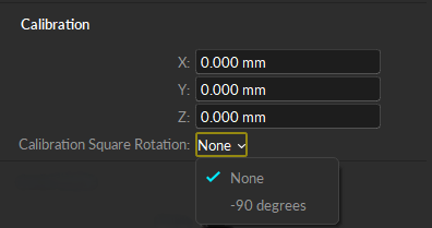
X/Y/Z Coordinates
Adjust the pivot point along the x/y/z axis.
Calibration Square Rotation (Advanced)
Determines the location of the force plate relative to the calibration square. Use None (the default) if placing the calibration square on top of the force plate in the lower right corner. Select -90 degrees if the square is placed next to the force plate, against the lower right corner.
Advanced
The items available in the Advanced section are for use by OptiTrack Support. This section is available only when the Advanced Settings are displayed.
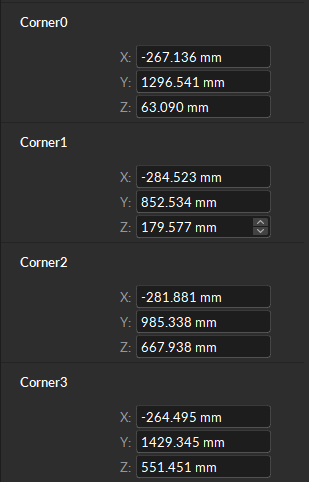
Corners
Displays the positions of the four force plate corners. Positions are measured with respect to the global coordinate system, which is calibrated when you Set Position using the CS-400 calibration square.
Last updated
Was this helpful?

