LogoLogo
WebsiteSupportDownloadsForumsQuick LinksContact Us
v3.2
v3.2
  • OptiTrack Documentation
  • WHAT'S NEW
    • What's New in Motive 3.2
  • QUICK START GUIDES
    • Quick Start Guide: Getting Started
    • Quick Start Guide: Prime Color Camera Setup
    • Quick Start Guide: Precision Capture
    • Quick Start Guide: Tutorial Videos
    • Quick Start Guide: Active Marker Tracking
    • Quick Start Guide: Outdoor Tracking Setup
  • HARDWARE
    • Cameras
      • Ethernet Cameras
        • PrimeX 120
        • PrimeX 41
        • PrimeX 22
        • PrimeX 13
        • PrimeX 13W
        • SlimX 13
        • Prime Color
        • VersaX 22
        • VersaX 41
        • VersaX 120
      • USB Cameras
        • Slim 3U
        • Flex 13
        • Flex 3
        • V120:Duo
        • V120:Trio
        • Adjusting Global Origin for Tracking Bars
    • Prepare Setup Area
    • Camera Mount Structures
    • Camera Placement
    • Ethernet Camera Network Setup
      • General Overview and Specs
      • Windows 10 Network Settings
      • Cabling and Load Balancing
      • Switch Configuration for PrimeX 120
      • NETGEAR ProSafe GSM7228S: Disabling the Broadcast Storm Control
      • White/Blacklisting Cameras
    • USB Camera System Setup
      • USB Camera Network Overview and Specs
      • V120:Duo and Trio Setup
      • Tracking Bar Coordinate System
        • Transforming Coordinate System: Global to Local
    • Aiming and Focusing
    • Camera Status Indicators
  • MOTIVE
    • Installation and License Activation
    • Motive Basics
    • Calibration
      • .mcal XML Calibration Files
      • Continuous Calibration
      • Continuous Calibration (Info Pane)
      • Calibration Squares
    • Markers
    • Assets
      • Gizmo Tool: Translate, Rotate, and Scale
    • Rigid Body Tracking
      • Aligning Rigid Body Pivot Point with a Replicated 3D Model
    • Skeleton Tracking
    • Trained Markersets
    • IMU Sensor Fusion
    • Data Recording
      • Data Types
    • Labeling
    • Data Editing
    • Data Export
      • Data Export: BVH
      • Data Export: C3D
      • Data Export: CSV
      • Data Export: FBX
      • Data Export: TRC
    • Data Streaming
    • Camera Video Types
    • Audio Recording
    • Motive HotKeys
    • Measurement Probe Kit Guide
    • Motive Batch Processor
    • Reconstruction and 2D Mode
  • MOTIVE UI PANES
    • Settings
      • Settings: General
      • Settings: Assets
      • Settings: Live Pipeline
      • Settings: Streaming
      • Settings: Views
      • Settings: Mouse and Keyboard
      • Settings: Audio
    • Assets Pane
    • Builder Pane
    • Constraints Pane
      • Constraints XML Files
    • Calibration Pane
    • Data Pane
    • Devices Pane
    • Edit Tools Pane
    • Graph View Pane
    • Info Pane
    • Labels Pane
    • Log Pane
    • Probe Pane
    • Properties Pane
      • Properties Pane: Camera
      • Properties Pane: Force Plates
      • Properties Pane: NI-DAQ
      • Properties Pane: OptiHub2
      • Properties Pane: Rigid Body
      • Properties Pane: Skeleton
      • Properties Pane: Take
      • Properties Pane: Trained Markerset
      • Properties Pane: eSync2
    • Status Panel
    • Toolbar/Command Bar
    • Control Deck
    • Viewport
  • PLUGINS
    • OptiTrack Blender Plugin
      • OptiTrack Blender Plugin
    • OptiTrack Unreal Engine Plugin
      • Unreal Engine: OptiTrack Live Link Plugin
        • Quick Start Guide: Real-Time Retargeting in Unreal Engine with Live Link Content
        • Unreal Editor for Fortnite (UEFN): OptiTrack Plugin for Live Link Hub
        • Unreal Engine: Live Link Camera Stream Setup
        • Live Link Content: Active Puck Static Meshes
      • Unreal Engine: MotionBuilder Workflow
      • Unreal Engine: HMD Setup
      • Unreal Engine VCS Inputs
    • OptiTrack Unity Plugin
      • Unity: HMD Setup
    • OptiTrack OpenVR Driver
    • OptiTrack MATLAB Plugin
    • Autodesk Maya
      • Autodesk Maya: OptiTrack Insight VCS Plugin
    • Autodesk MotionBuilder
      • Autodesk MotionBuilder Plugin
      • Autodesk MotionBuilder: OptiTrack Skeleton Plugin
      • Autodesk MotionBuilder: OptiTrack Optical Plugin
      • Autodesk MotionBuilder: OptiTrack Insight VCS Plugin
      • Autodesk MotionBuilder: Timecode Data
    • OptiTrack Peripheral API
    • External Plugins
      • Houdini 19 Integration
  • ACTIVE COMPONENTS
    • Active Components Hardware
      • Active Puck
      • Wired AnchorPuck
      • CinePuck
      • Wired CinePuck
      • BaseStation
      • Information for Assembling the Active Tags
      • Manus Glove Setup
    • Configuration
      • Active Batch Programmer
      • Active Hardware Configuration: PuTTY
      • Active Component Firmware Compatibility
    • Active Marker Tracking
      • Active Finger Marker Set
  • SYNCHRONIZATION
    • Synchronization Hardware
      • External Device Sync Guide: eSync 2
      • External Device Sync Guide: OptiHub2
    • Synchronization Setup
    • OptiTrack Timecode
  • VIRTUAL PRODUCTION
    • Unreal Engine: OptiTrack InCamera VFX
    • Entertainment Marker Sets
    • PrimeX 41
  • MOVEMENT SCIENCES
    • Movement Sciences Hardware
      • General Motive Force Plate Setup
      • AMTI Force Plate Setup
      • Bertec Force Plate Setup
      • Kistler Force Plate Setup
      • Delsys EMG Setup
      • NI-DAQ Setup
      • Multiple Device Setup
    • Movement Sciences Marker Sets
      • Biomechanics Marker Sets
      • Biomech (57)
      • Rizzoli Marker Sets
    • For Visual3D Users
    • Prime Color Camera Setup
      • Prime Color Setup: Required Components
      • Prime Color Setup: Hardware Setup
      • Prime Color Camera Setup: Camera Settings
      • Prime Color Camera Setup: Prime Color FS Calibration
      • Prime Color Setup: Data Recording / Export
      • Prime Color Camera Setup: FAQ / Troubleshooting
      • Prime Color Camera Setup: Windows Network Settings
  • VIRTUAL REALITY
    • VR Plugins
      • VR Unreal Engine
        • OptiTrack Unreal Engine Plugin
        • Unreal Engine: OptiTrack Live Link Plugin
          • UE5.1 Live Link Retarget External Workaround
        • Unreal Engine VCS Inputs
      • VR Unity
        • OptiTrack Unity Plugin
      • VR OpenVR
        • OptiTrack OpenVR Driver
    • VR HMD Setup
      • Unreal Engine: HMD Setup
      • Unity: HMD Setup
      • Manually Calibrating the HMD Pivot Point
      • Sync Configuration with an HTC Vive System
    • SlimX 13
    • Active Marker Tracking
      • Active Finger Marker Set
    • Synchronization Hardware
      • External Device Sync Guide: eSync 2
      • External Device Sync Guide: OptiHub2
  • ANIMATION
    • Autodesk Maya
      • Autodesk Maya: OptiTrack Insight VCS Plugin
    • Autodesk MotionBuilder
      • Autodesk MotionBuilder Plugin
      • Autodesk MotionBuilder: OptiTrack Skeleton Plugin
      • Autodesk MotionBuilder: OptiTrack Optical Plugin
      • Autodesk MotionBuilder: OptiTrack Insight VCS Plugin
      • Autodesk MotionBuilder: Timecode Data
  • ROBOTICS
    • MoCap4ROS2 Setup
    • OptiTrack Robot Applications
    • Outdoor Tracking Setup
  • DEVELOPER TOOLS
    • Developer Tools Overview
    • Camera SDK
      • Class: cCameraModule
      • Class: cUID
    • Motive API
      • Motive API: Quick Start Guide
      • Motive API Overview
      • Motive API: Function Reference
      • Motive API Camera Calibration
    • NatNet SDK
      • NatNet 4.1
      • NatNet: Class/Function Reference
      • NatNet: Creating a Managed (C sharp) Client Application
      • NatNet: Creating a Native (C++) Client Application
      • NatNet: Data Types
      • NatNet: Matlab Wrapper
      • NatNet: Migration to NatNet 3.0 libraries
      • NatNet: Remote Requests/Commands
      • NatNet: Sample Projects
      • NatNet: Unicast Data Subscription Commands
      • Latency Measurements
    • VRPN Sample
    • Peripheral API: Glove Devices
  • SKELETON MARKER SETS
    • Full Body
      • Baseline (41)
      • Core (50)
      • Biomech (57)
      • Conventional (39)
    • Full Body + Fingers
      • Baseline + Passive Fingers (49)
      • Baseline + Active Fingers (57)
      • Core + Passive Fingers (54)
      • Core + Active Fingers (62)
    • Upper
      • Baseline Upper (25)
      • Conventional Upper (27)
    • Lower
      • Baseline Lower (20)
      • Helen Hayes Lower (19)
      • Conventional Lower (16)
    • Hand and Fingers
      • Left/Right Hand (4) Active
      • Left/Right Hand (10) Active + Passive
      • Active Finger Marker Set
    • Glove Device Setup
      • Manus Glove Setup
      • StretchSense Glove Setup
    • Rizzoli Marker Sets
    • Entertainment Marker Sets
    • Rigid Body Skeleton Marker Set
  • GENERAL TROUBLESHOOTING
    • Licensing Troubleshooting
    • Windows 11 Optimization for Realtime Applications
    • Network Troubleshooting
    • Troubleshooting Q&A
    • Running Motive on High DPI Displays
    • Firewall Settings
Powered by GitBook
On this page

Was this helpful?

Export as PDF
  1. VIRTUAL REALITY
  2. VR HMD Setup

Sync Configuration with an HTC Vive System

PreviousManually Calibrating the HMD Pivot PointNextSlimX 13

Was this helpful?

OpenVR Driver

This synchronization setup is not required for integrating HTC Vive with OptiTrack system. For integrating HTC Vive with OptiTrack system, please use the . This driver will completely override the tracking of an HTC Vive HMD so that the HMD can be tracked just using the OptiTrack system without the lighthouse base stations, and when using the OpenVR driver, synchronization between two systems is not necessary. This article is for specific applications where both lighthouse base station and the OptiTrack system must be running simultaneously.

To download the driver, visit the of the OptiTrack page.

Notes on the Sync Settings

The sync settings listed on this page have not been tested with the latest version of the firmware. This means that the appropriate sync offset value indicated on this page might not be correct. For integrating into SteamVR, please consider using the to completely override the tracking.

This article provides instructions on how to synchronize an OptiTrack Motion Capture system with an HTC Vive virtual reality system, specifically the lighthouse base stations, to avoid overlapping of the infrared tracking lights. The HTC Vive system also uses infrared LEDs and lasers for tracking its head-mounted display (HMD) and controllers. When using an OptiTrack mocap system in conjunction with the HTC Vive system, the infrared tracking from the two systems can interfere with each other. For this reason, the two systems must be synchronized in a way so that the two different tracking lights do not temporally overlap. Currently, sync configurations with only OptiTrack Prime-series camera systems have been tested.

Let’s go through the synchronization setup. The following setup instructions assume that the two tracking base stations of the HTC Vive system are set to channel b and c and are optically synchronized. The channel b base station will serve as the master device for synchronizing the two systems. Sync out signal from the channel b station will feed into one of the input ports on the eSync 2, and a sync offset (specified in microseconds, or μs) will be applied to so that IR lights from the two systems don’t interfere with each other. The following section describes the instructions in detail.

Note:

  • The eSync 2 is required in order to synchronize HTC Vive lighthouses with the camera system.

  • Synchronization with Flex camera systems is not supported.

Synchronization Configuration

Step 1: Set up the HTC Vive system.

The base stations will synchronize optically in this setup. Refer to the respective documentation for more details on setting up the HTC Vive system. Set the tracking stations to channels b and c, so that they are optically synchronized (in the absence of a sync cable connection between them).

Step 2: Set up the OptiTrack mocap system.

Refer to the wiki pages for more details.

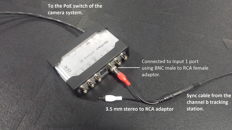
Step 3: Connect the sync output from the channel b base station into the input port 1 of the eSync 2 synchronization hub.
Step 4: Motive: Synchronization pane. Configure the synchronization in Motive.

Open the Synchronization pane in Motive, and set the synchronization type to Custom Synchronization.

Step 5: Motive: Synchronization pane. Configure the Sync Input.

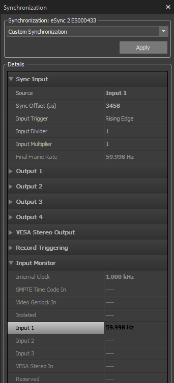
Set the Sync Input to Input 1, which was the input port of the eSync 2 where the sync cable was connected to. If the sync cable is properly connected and the HTC Vive system is properly working, the bottom signal monitor will display a frequency of approximately 60 Hz detected through the Input 1 port of the eSync 2. Note that this configuration will synchronize the OptiTrack camera system to the sync signal coming through the Input port.

Step 6: Motive: Synchronization pane. Introduce Sync Offset (μs).
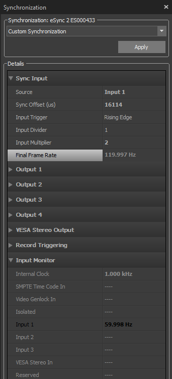
Now that the OptiTrack system’s shutter timing is synchronized with the base stations of the HTC Vive system, you will need to introduce a sync offset to avoid overlapping of the tracking lights. The following list of offset sync parameters are tested to avoid the interference. Input these parameters into the Synchronization pane. If you wish to increase the final frame rate of the mocap system, you will need to apply a multiplier.

  • Final Frame Rate: 120 Hz

  • Sync Multiplier: 2

  • Sync Offset: 1780 μs

  • Final Frame Rate: 240 Hz

  • Sync Multiplier: 4

  • Sync Offset: 3150 μs

Notes on the Sync Settings

Step 7: Motive: Synchronization pane. Apply sync configuration.

Press Apply to employ the sync configuration. The tracking IR lights from both systems will no longer interfere, and the HTC Vive components will be working properly and available in the SteamVR application.

Step 8: Motive: Cameras pane. Lower the camera exposure on the OptiTrack system.

Another important note is that high camera exposure settings may cause IR light from the base stations to be detected by the OptiTrack system. It's suggested to keep the camera exposure below 1000 us for all of the cameras.

Now that the two systems are synchronized to avoid the IR interference, both systems can be used together to provide immersive VR experiences. Note that the instructions listed on this page are tested to work with HTC Vive system, but alternative approaches may also be possible.

The sync output of the base stations use 3.5 mm stereo (TRS) cables, whereas the Input ports of the eSync 2 are BNC ports. You will need to use a stereo female to RCA male adapter (e.g. ) as well as an RCA-to-BNC adaptor (included with the eSync 2) to connect the channel b base station and the eSync 2 hub. After attaching the stereo to RCA adaptor, connect the red RCA cable into the eSync 2 using a BNC adapter, as shown in the following photo.

The sync settings listed on this page have not been tested with the latest version of the firmware. This means that the appropriate sync offset value indicated on this page might not be correct. For integrating into SteamVR, please consider using to completely override the tracking.

OptiTrack OpenVR Driver
Plug-ins section
Downloads
OptiTrack OpenVR Driver
Hardware Setup
http://www.monoprice.com/product?p_id=5612
OptiTrack OpenVR Driver
Connecting an HTC Vive system into the eSync 2.
Custom synchronization configuration without applying multipliers to the final frame rate. 60 Hz input signal detected for the connected input under the Input Monitor.
Custom synchronization configuration with multiplier (X2) applied to the input signal, resulting in final frame rate of approx. 120 Hz.