LogoLogo
WebsiteSupportDownloadsForumsQuick LinksContact Us
v3.2
v3.2
  • OptiTrack Documentation
  • WHAT'S NEW
    • What's New in Motive 3.2
  • QUICK START GUIDES
    • Quick Start Guide: Getting Started
    • Quick Start Guide: Prime Color Camera Setup
    • Quick Start Guide: Precision Capture
    • Quick Start Guide: Tutorial Videos
    • Quick Start Guide: Active Marker Tracking
    • Quick Start Guide: Outdoor Tracking Setup
  • HARDWARE
    • Cameras
      • Ethernet Cameras
        • PrimeX 120
        • PrimeX 41
        • PrimeX 22
        • PrimeX 13
        • PrimeX 13W
        • SlimX 13
        • Prime Color
        • VersaX 22
        • VersaX 41
        • VersaX 120
      • USB Cameras
        • Slim 3U
        • Flex 13
        • Flex 3
        • V120:Duo
        • V120:Trio
        • Adjusting Global Origin for Tracking Bars
    • Prepare Setup Area
    • Camera Mount Structures
    • Camera Placement
    • Ethernet Camera Network Setup
      • General Overview and Specs
      • Windows 10 Network Settings
      • Cabling and Load Balancing
      • Switch Configuration for PrimeX 120
      • NETGEAR ProSafe GSM7228S: Disabling the Broadcast Storm Control
      • White/Blacklisting Cameras
    • USB Camera System Setup
      • USB Camera Network Overview and Specs
      • V120:Duo and Trio Setup
      • Tracking Bar Coordinate System
        • Transforming Coordinate System: Global to Local
    • Aiming and Focusing
    • Camera Status Indicators
  • MOTIVE
    • Installation and License Activation
    • Motive Basics
    • Calibration
      • .mcal XML Calibration Files
      • Continuous Calibration
      • Continuous Calibration (Info Pane)
      • Calibration Squares
    • Markers
    • Assets
      • Gizmo Tool: Translate, Rotate, and Scale
    • Rigid Body Tracking
      • Aligning Rigid Body Pivot Point with a Replicated 3D Model
    • Skeleton Tracking
    • Trained Markersets
    • IMU Sensor Fusion
    • Data Recording
      • Data Types
    • Labeling
    • Data Editing
    • Data Export
      • Data Export: BVH
      • Data Export: C3D
      • Data Export: CSV
      • Data Export: FBX
      • Data Export: TRC
    • Data Streaming
    • Camera Video Types
    • Audio Recording
    • Motive HotKeys
    • Measurement Probe Kit Guide
    • Motive Batch Processor
    • Reconstruction and 2D Mode
  • MOTIVE UI PANES
    • Settings
      • Settings: General
      • Settings: Assets
      • Settings: Live Pipeline
      • Settings: Streaming
      • Settings: Views
      • Settings: Mouse and Keyboard
      • Settings: Audio
    • Assets Pane
    • Builder Pane
    • Constraints Pane
      • Constraints XML Files
    • Calibration Pane
    • Data Pane
    • Devices Pane
    • Edit Tools Pane
    • Graph View Pane
    • Info Pane
    • Labels Pane
    • Log Pane
    • Probe Pane
    • Properties Pane
      • Properties Pane: Camera
      • Properties Pane: Force Plates
      • Properties Pane: NI-DAQ
      • Properties Pane: OptiHub2
      • Properties Pane: Rigid Body
      • Properties Pane: Skeleton
      • Properties Pane: Take
      • Properties Pane: Trained Markerset
      • Properties Pane: eSync2
    • Status Panel
    • Toolbar/Command Bar
    • Control Deck
    • Viewport
  • PLUGINS
    • OptiTrack Blender Plugin
      • OptiTrack Blender Plugin
    • OptiTrack Unreal Engine Plugin
      • Unreal Engine: OptiTrack Live Link Plugin
        • Quick Start Guide: Real-Time Retargeting in Unreal Engine with Live Link Content
        • Unreal Editor for Fortnite (UEFN): OptiTrack Plugin for Live Link Hub
        • Unreal Engine: Live Link Camera Stream Setup
        • Live Link Content: Active Puck Static Meshes
      • Unreal Engine: MotionBuilder Workflow
      • Unreal Engine: HMD Setup
      • Unreal Engine VCS Inputs
    • OptiTrack Unity Plugin
      • Unity: HMD Setup
    • OptiTrack OpenVR Driver
    • OptiTrack MATLAB Plugin
    • Autodesk Maya
      • Autodesk Maya: OptiTrack Insight VCS Plugin
    • Autodesk MotionBuilder
      • Autodesk MotionBuilder Plugin
      • Autodesk MotionBuilder: OptiTrack Skeleton Plugin
      • Autodesk MotionBuilder: OptiTrack Optical Plugin
      • Autodesk MotionBuilder: OptiTrack Insight VCS Plugin
      • Autodesk MotionBuilder: Timecode Data
    • OptiTrack Peripheral API
    • External Plugins
      • Houdini 19 Integration
  • ACTIVE COMPONENTS
    • Active Components Hardware
      • Active Puck
      • Wired AnchorPuck
      • CinePuck
      • Wired CinePuck
      • BaseStation
      • Information for Assembling the Active Tags
      • Manus Glove Setup
    • Configuration
      • Active Batch Programmer
      • Active Hardware Configuration: PuTTY
      • Active Component Firmware Compatibility
    • Active Marker Tracking
      • Active Finger Marker Set
  • SYNCHRONIZATION
    • Synchronization Hardware
      • External Device Sync Guide: eSync 2
      • External Device Sync Guide: OptiHub2
    • Synchronization Setup
    • OptiTrack Timecode
  • VIRTUAL PRODUCTION
    • Unreal Engine: OptiTrack InCamera VFX
    • Entertainment Marker Sets
    • PrimeX 41
  • MOVEMENT SCIENCES
    • Movement Sciences Hardware
      • General Motive Force Plate Setup
      • AMTI Force Plate Setup
      • Bertec Force Plate Setup
      • Kistler Force Plate Setup
      • Delsys EMG Setup
      • NI-DAQ Setup
      • Multiple Device Setup
    • Movement Sciences Marker Sets
      • Biomechanics Marker Sets
      • Biomech (57)
      • Rizzoli Marker Sets
    • For Visual3D Users
    • Prime Color Camera Setup
      • Prime Color Setup: Required Components
      • Prime Color Setup: Hardware Setup
      • Prime Color Camera Setup: Camera Settings
      • Prime Color Camera Setup: Prime Color FS Calibration
      • Prime Color Setup: Data Recording / Export
      • Prime Color Camera Setup: FAQ / Troubleshooting
      • Prime Color Camera Setup: Windows Network Settings
  • VIRTUAL REALITY
    • VR Plugins
      • VR Unreal Engine
        • OptiTrack Unreal Engine Plugin
        • Unreal Engine: OptiTrack Live Link Plugin
          • UE5.1 Live Link Retarget External Workaround
        • Unreal Engine VCS Inputs
      • VR Unity
        • OptiTrack Unity Plugin
      • VR OpenVR
        • OptiTrack OpenVR Driver
    • VR HMD Setup
      • Unreal Engine: HMD Setup
      • Unity: HMD Setup
      • Manually Calibrating the HMD Pivot Point
      • Sync Configuration with an HTC Vive System
    • SlimX 13
    • Active Marker Tracking
      • Active Finger Marker Set
    • Synchronization Hardware
      • External Device Sync Guide: eSync 2
      • External Device Sync Guide: OptiHub2
  • ANIMATION
    • Autodesk Maya
      • Autodesk Maya: OptiTrack Insight VCS Plugin
    • Autodesk MotionBuilder
      • Autodesk MotionBuilder Plugin
      • Autodesk MotionBuilder: OptiTrack Skeleton Plugin
      • Autodesk MotionBuilder: OptiTrack Optical Plugin
      • Autodesk MotionBuilder: OptiTrack Insight VCS Plugin
      • Autodesk MotionBuilder: Timecode Data
  • ROBOTICS
    • MoCap4ROS2 Setup
    • OptiTrack Robot Applications
    • Outdoor Tracking Setup
  • DEVELOPER TOOLS
    • Developer Tools Overview
    • Camera SDK
      • Class: cCameraModule
      • Class: cUID
    • Motive API
      • Motive API: Quick Start Guide
      • Motive API Overview
      • Motive API: Function Reference
      • Motive API Camera Calibration
    • NatNet SDK
      • NatNet 4.1
      • NatNet: Class/Function Reference
      • NatNet: Creating a Managed (C sharp) Client Application
      • NatNet: Creating a Native (C++) Client Application
      • NatNet: Data Types
      • NatNet: Matlab Wrapper
      • NatNet: Migration to NatNet 3.0 libraries
      • NatNet: Remote Requests/Commands
      • NatNet: Sample Projects
      • NatNet: Unicast Data Subscription Commands
      • Latency Measurements
    • VRPN Sample
    • Peripheral API: Glove Devices
  • SKELETON MARKER SETS
    • Full Body
      • Baseline (41)
      • Core (50)
      • Biomech (57)
      • Conventional (39)
    • Full Body + Fingers
      • Baseline + Passive Fingers (49)
      • Baseline + Active Fingers (57)
      • Core + Passive Fingers (54)
      • Core + Active Fingers (62)
    • Upper
      • Baseline Upper (25)
      • Conventional Upper (27)
    • Lower
      • Baseline Lower (20)
      • Helen Hayes Lower (19)
      • Conventional Lower (16)
    • Hand and Fingers
      • Left/Right Hand (4) Active
      • Left/Right Hand (10) Active + Passive
      • Active Finger Marker Set
    • Glove Device Setup
      • Manus Glove Setup
      • StretchSense Glove Setup
    • Rizzoli Marker Sets
    • Entertainment Marker Sets
    • Rigid Body Skeleton Marker Set
  • GENERAL TROUBLESHOOTING
    • Licensing Troubleshooting
    • Windows 11 Optimization for Realtime Applications
    • Network Troubleshooting
    • Troubleshooting Q&A
    • Running Motive on High DPI Displays
    • Firewall Settings
Powered by GitBook
On this page
  • Synchronization Control
  • Sync Input Settings
  • Source: Internal/Wired
  • Source: Sync In
  • Source: USB Sync
  • Input Trigger Options
  • External Sync Output
  • Pulse Type

Was this helpful?

Export as PDF
  1. MOTIVE UI PANES
  2. Properties Pane

Properties Pane: OptiHub2

PreviousProperties Pane: NI-DAQNextProperties Pane: Rigid Body

Was this helpful?

Important Note

Please note that the OptiHub2 is not designed for precise synchronization with external devices. It is used to provide only a rough synchronization to a trigger event on the input/output signal. Using an OptiHub2, there will be some amount of time delay between the trigger events and the desired actions, and for this reason, the OptiHub2 is not suitable for the precisely synchronizing to an external device. To accomplish such synchronization, it is recommended to use the instead along with an Ethernet camera system.

By modifying the device properties of the OptiHub, users can customize the sync configurations of the camera system for implementing external devices in various sync chain setups. This page directly lists out the properties of the OptiHub. For general instructions on customizing sync settings for integrating external devices, it is recommended to read through the guide.

Synchronization Control

Internal Sync Freq (Hz)

This option is only valid if the Sync Input: Source is set to Internal Sync. Controls the frequency in Hertz (Hz) of the OptiHub 2's internal sync generator. Valid frequency range is 8 to 120 Hz.

Global Sync Offset (us)

This option is only valid if the Sync Input: Source is set to Sync In or USB Sync_. Controls synchronization delay in microseconds (us) between the chosen sync source signal and when the cameras are actually told to expose. This is a global system delay that is independent of, and in addition to, an individual camera's exposure delay setting. Valid range is 0 to 65862 us, and should not exceed one frame period of the external signal._

Sync Input Settings

To setup the sync input signals, first define a input Source and configure desired trigger settings for the source:

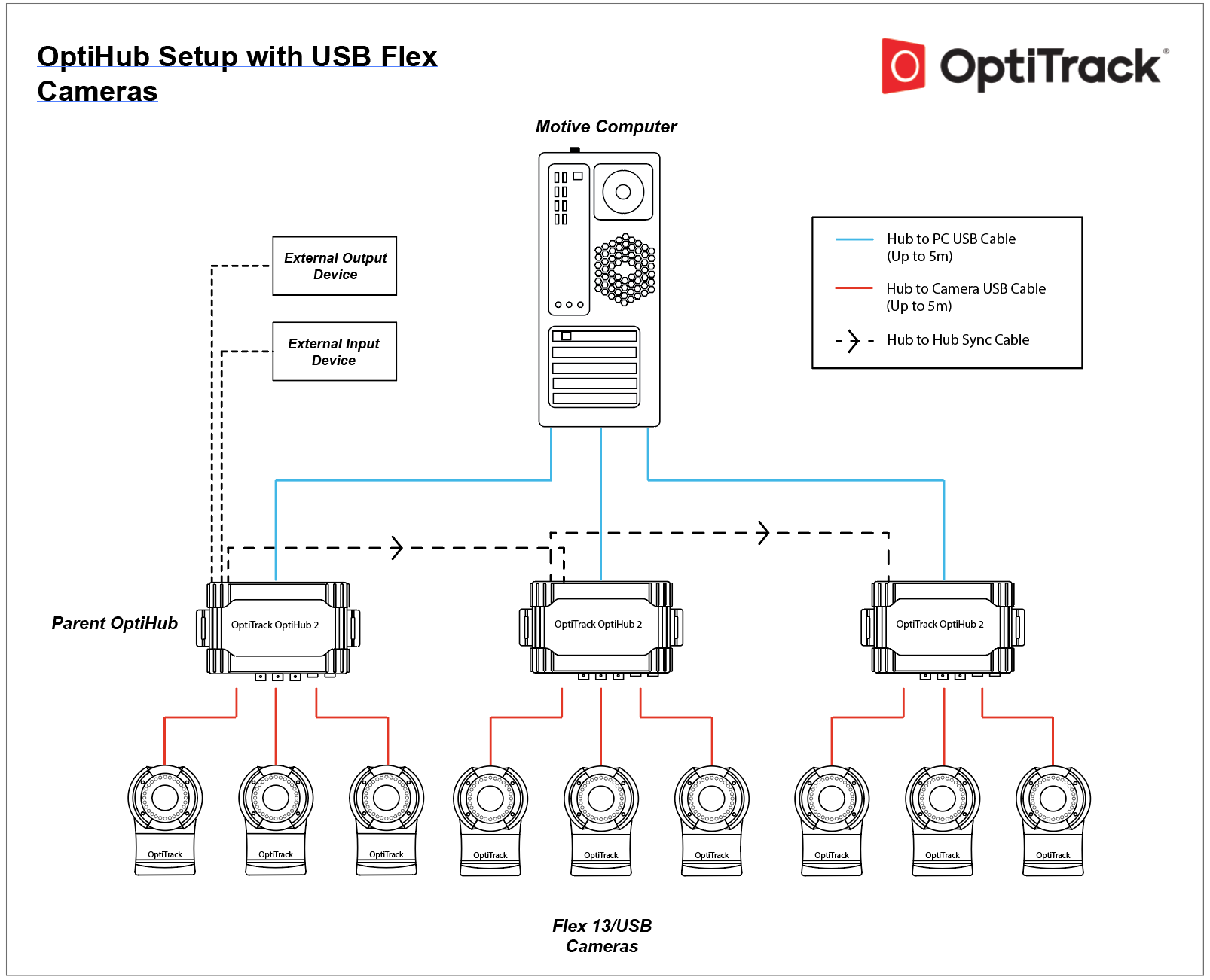
  • Internal/Wired sets the OptiHub 2 as the sync source. This is the default sync configuration which uses the OptiSync protocol for synchronizing the cameras. The Parent OptiHub 2 will generate an internal sync signal which will be propagated to other (child) OptiHub 2(s) via the Hub Sync Out Jack and Hub Sync In Jack. For V100:R1(legacy) and the Slim 3U cameras, Wired Sync protocol is used. In this mode, the internal sync signal will still be generated but it will be routed directly to the cameras via daisy-chained sync cables.

  • Sync In sets an external device as the sync source.

Source: Internal/Wired

Internal Sync Freq (Hz)

This option is only valid if the Sync Input: Source is set to Internal Sync. Controls the frequency in Hertz (Hz) of the OptiHub 2's internal sync generator, and the this frequency will control the camera system frame rate. Valid frequency range is 8 to 120 Hz.

Source: Sync In

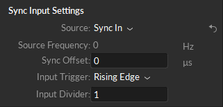
Source Frequency

Detects and displays the frequency of the sync signal that's coming through the input port of the parent OptiHub 2, which is at the very top of the RCA sync chain. When sync source is set to Sync In, the camera system framerate will be synchronized to this input signal. Please note that OptiHub 2 is not designed for precise sync, so there may be slight sync discrepancies when synchronizing through OptiHub 2.

Sync Offset

Manually adds global sync time offset to how camera system reacts to the received input signal. The input unit is measured in microseconds.

Input Trigger

Can select from Either Edge, Rising Edge, Falling Edge, Low Gated, or High Gated signal from the connected input source.

Input Divider

Allows a triggering rate compatible with the camera frame rate to be derived from higher frequency input signals (e.g. 300Hz decimated down to 100Hz for use with a V100:R2 camera). Valid range is 1 (no decimation) to 15 (every 15th trigger signal generates a frame).

Source: USB Sync

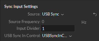
Source Frequency

Detects and displays the frequency of the parent source.

USB Sync-In Control

Allows the user to allow or block trigger events generated by the internal sync control. This option has been deprecated for use in the GUI. Valid options are Gate-Open and Gate-Closed.

Input Divider

Allows a triggering rate compatible with the camera frame rate to be derived from higher frequency input signals (e.g. 360Hz decimated down to 120Hz for use with a Flex 13 camera). Valid range is 1 (no decimation) to 15 (every 15th trigger signal generates a frame).}}

Input Trigger Options

Trigger
Description

Either Edge

Uses either the rising or falling edge of the pulse signal.

Rising Edge

Uses the rising edge of the pulse signal.

Falling Edge

Uses the falling edge of the pulse signal.

High Gated

High Gated mode triggers when the input signal is at a high voltage level, but stops triggering at a low voltage level.

Low Gated

Low Gated mode triggers when the input signal is at a low voltage level, but stops triggering at a high voltage level.

External Sync Output

Pulse Type

Selects condition and timing for a pulse to be sent out over the External Sync Out jack. Available Types are: Exposure Time, Pass-Through, Recording Level, and Recording Pulse.

External Sync Output Options

Output
Description

Exposure Time

Outputs a pulse signal when the cameras expose.

Pass-Through

Passes the input signal to the output.

Recording Gate

Outputs a constant high level signal while recording. Other times the signal is low. (Referred as Recording Level in older versions).

Gated Exposure Time

Outputs a pulse signal when the cameras expose during a recording only. (Referred as Recording Pulse in older versions).

Polarity

Selects output polarity of External Sync Out signal. Valid options are: Normal and Inverted. Normal signals are low and pulse high and inverted signals are high and pulse low.

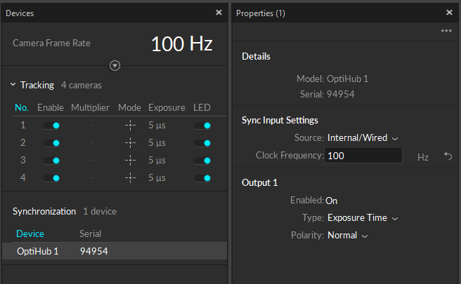
While the OptiHub is selected under the , use the to view and configure its properties. By doing so, users can set the parent sync source for the camera system, configure how the system reacts to input signals, and also which signals to output from the OptiHub for triggering other external acquisition devices.
USB Sync sets an external USB device as the sync source. This mode is for customers who use the development kits and would like to have their software trigger the cameras instead. Using the provided API, the OptiHub 2 will be send the trigger signal from the PC via the OptiHib 2's USB uplink connection to the PC.

The Internal/Wired input source uses the OptiHub 2's internal synchronization generator as the main sync source. You can modify the synchronization frequency for both protocol under the Synchronization Control section. When you adjust the system frame rate from this panel, the modified frame rate may not be reflected on the Devices pane. Check the streaming section of the status bar for the exact information.

The Sync In input source setting uses signals coming into the input ports of the OptiHub 2 to trigger the synchronization. Please refer to External page for more instructions on this.

(The camera system will be the child) sets an external USB device as the sync source. This mode is for customers who use the development kits and would like to have their software trigger the cameras instead. Using the provided API, the OptiHub 2 will be send the trigger signal from the PC via the OptiHib 2's USB uplink connection to the PC.

Sync signals can also be sent out through the output ports of the OptiHub 2 to child devices in the synchronization chain. Read more: .

Devices pane
Properties pane
Camera SDK
Wired and OptiSync
Device Sync Guide: OptiHub 2
Camera SDK
External Device Sync Guide: OptiHub 2
eSync 2
External Device Sync Guide: OptiHub 2
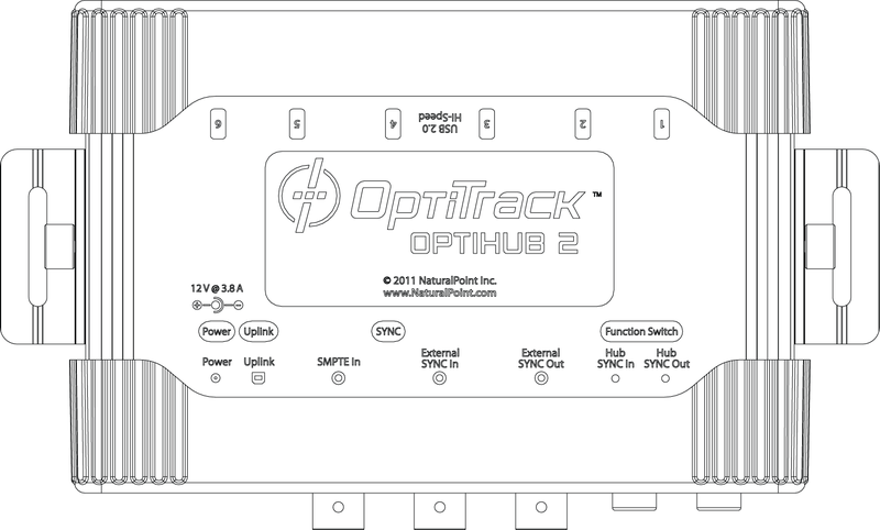
OptiHub 2 properties.
Sync settings when the input sync source is set to Internal/Wired.
Input sync settings when the source is set to Sync In.
Sync settings when the input sync source is set to USB sync.