LogoLogo
WebsiteSupportDownloadsForumsQuick LinksContact Us
v3.2
v3.2
  • OptiTrack Documentation
  • WHAT'S NEW
    • What's New in Motive 3.2
  • QUICK START GUIDES
    • Quick Start Guide: Getting Started
    • Quick Start Guide: Prime Color Camera Setup
    • Quick Start Guide: Precision Capture
    • Quick Start Guide: Tutorial Videos
    • Quick Start Guide: Active Marker Tracking
    • Quick Start Guide: Outdoor Tracking Setup
  • HARDWARE
    • Cameras
      • Ethernet Cameras
        • PrimeX 120
        • PrimeX 41
        • PrimeX 22
        • PrimeX 13
        • PrimeX 13W
        • SlimX 13
        • Prime Color
        • VersaX 22
        • VersaX 41
        • VersaX 120
      • USB Cameras
        • Slim 3U
        • Flex 13
        • Flex 3
        • V120:Duo
        • V120:Trio
        • Adjusting Global Origin for Tracking Bars
    • Prepare Setup Area
    • Camera Mount Structures
    • Camera Placement
    • Ethernet Camera Network Setup
      • General Overview and Specs
      • Windows 10 Network Settings
      • Cabling and Load Balancing
      • Switch Configuration for PrimeX 120
      • NETGEAR ProSafe GSM7228S: Disabling the Broadcast Storm Control
      • White/Blacklisting Cameras
    • USB Camera System Setup
      • USB Camera Network Overview and Specs
      • V120:Duo and Trio Setup
      • Tracking Bar Coordinate System
        • Transforming Coordinate System: Global to Local
    • Aiming and Focusing
    • Camera Status Indicators
  • MOTIVE
    • Installation and License Activation
    • Motive Basics
    • Calibration
      • .mcal XML Calibration Files
      • Continuous Calibration
      • Continuous Calibration (Info Pane)
      • Calibration Squares
    • Markers
    • Assets
      • Gizmo Tool: Translate, Rotate, and Scale
    • Rigid Body Tracking
      • Aligning Rigid Body Pivot Point with a Replicated 3D Model
    • Skeleton Tracking
    • Trained Markersets
    • IMU Sensor Fusion
    • Data Recording
      • Data Types
    • Labeling
    • Data Editing
    • Data Export
      • Data Export: BVH
      • Data Export: C3D
      • Data Export: CSV
      • Data Export: FBX
      • Data Export: TRC
    • Data Streaming
    • Camera Video Types
    • Audio Recording
    • Motive HotKeys
    • Measurement Probe Kit Guide
    • Motive Batch Processor
    • Reconstruction and 2D Mode
  • MOTIVE UI PANES
    • Settings
      • Settings: General
      • Settings: Assets
      • Settings: Live Pipeline
      • Settings: Streaming
      • Settings: Views
      • Settings: Mouse and Keyboard
      • Settings: Audio
    • Assets Pane
    • Builder Pane
    • Constraints Pane
      • Constraints XML Files
    • Calibration Pane
    • Data Pane
    • Devices Pane
    • Edit Tools Pane
    • Graph View Pane
    • Info Pane
    • Labels Pane
    • Log Pane
    • Probe Pane
    • Properties Pane
      • Properties Pane: Camera
      • Properties Pane: Force Plates
      • Properties Pane: NI-DAQ
      • Properties Pane: OptiHub2
      • Properties Pane: Rigid Body
      • Properties Pane: Skeleton
      • Properties Pane: Take
      • Properties Pane: Trained Markerset
      • Properties Pane: eSync2
    • Status Panel
    • Toolbar/Command Bar
    • Control Deck
    • Viewport
  • PLUGINS
    • OptiTrack Blender Plugin
      • OptiTrack Blender Plugin
    • OptiTrack Unreal Engine Plugin
      • Unreal Engine: OptiTrack Live Link Plugin
        • Quick Start Guide: Real-Time Retargeting in Unreal Engine with Live Link Content
        • Unreal Editor for Fortnite (UEFN): OptiTrack Plugin for Live Link Hub
        • Unreal Engine: Live Link Camera Stream Setup
        • Live Link Content: Active Puck Static Meshes
      • Unreal Engine: MotionBuilder Workflow
      • Unreal Engine: HMD Setup
      • Unreal Engine VCS Inputs
    • OptiTrack Unity Plugin
      • Unity: HMD Setup
    • OptiTrack OpenVR Driver
    • OptiTrack MATLAB Plugin
    • Autodesk Maya
      • Autodesk Maya: OptiTrack Insight VCS Plugin
    • Autodesk MotionBuilder
      • Autodesk MotionBuilder Plugin
      • Autodesk MotionBuilder: OptiTrack Skeleton Plugin
      • Autodesk MotionBuilder: OptiTrack Optical Plugin
      • Autodesk MotionBuilder: OptiTrack Insight VCS Plugin
      • Autodesk MotionBuilder: Timecode Data
    • OptiTrack Peripheral API
    • External Plugins
      • Houdini 19 Integration
  • ACTIVE COMPONENTS
    • Active Components Hardware
      • Active Puck
      • Wired AnchorPuck
      • CinePuck
      • Wired CinePuck
      • BaseStation
      • Information for Assembling the Active Tags
      • Manus Glove Setup
    • Configuration
      • Active Batch Programmer
      • Active Hardware Configuration: PuTTY
      • Active Component Firmware Compatibility
    • Active Marker Tracking
      • Active Finger Marker Set
  • SYNCHRONIZATION
    • Synchronization Hardware
      • External Device Sync Guide: eSync 2
      • External Device Sync Guide: OptiHub2
    • Synchronization Setup
    • OptiTrack Timecode
  • VIRTUAL PRODUCTION
    • Unreal Engine: OptiTrack InCamera VFX
    • Entertainment Marker Sets
    • PrimeX 41
  • MOVEMENT SCIENCES
    • Movement Sciences Hardware
      • General Motive Force Plate Setup
      • AMTI Force Plate Setup
      • Bertec Force Plate Setup
      • Kistler Force Plate Setup
      • Delsys EMG Setup
      • NI-DAQ Setup
      • Multiple Device Setup
    • Movement Sciences Marker Sets
      • Biomechanics Marker Sets
      • Biomech (57)
      • Rizzoli Marker Sets
    • For Visual3D Users
    • Prime Color Camera Setup
      • Prime Color Setup: Required Components
      • Prime Color Setup: Hardware Setup
      • Prime Color Camera Setup: Camera Settings
      • Prime Color Camera Setup: Prime Color FS Calibration
      • Prime Color Setup: Data Recording / Export
      • Prime Color Camera Setup: FAQ / Troubleshooting
      • Prime Color Camera Setup: Windows Network Settings
  • VIRTUAL REALITY
    • VR Plugins
      • VR Unreal Engine
        • OptiTrack Unreal Engine Plugin
        • Unreal Engine: OptiTrack Live Link Plugin
          • UE5.1 Live Link Retarget External Workaround
        • Unreal Engine VCS Inputs
      • VR Unity
        • OptiTrack Unity Plugin
      • VR OpenVR
        • OptiTrack OpenVR Driver
    • VR HMD Setup
      • Unreal Engine: HMD Setup
      • Unity: HMD Setup
      • Manually Calibrating the HMD Pivot Point
      • Sync Configuration with an HTC Vive System
    • SlimX 13
    • Active Marker Tracking
      • Active Finger Marker Set
    • Synchronization Hardware
      • External Device Sync Guide: eSync 2
      • External Device Sync Guide: OptiHub2
  • ANIMATION
    • Autodesk Maya
      • Autodesk Maya: OptiTrack Insight VCS Plugin
    • Autodesk MotionBuilder
      • Autodesk MotionBuilder Plugin
      • Autodesk MotionBuilder: OptiTrack Skeleton Plugin
      • Autodesk MotionBuilder: OptiTrack Optical Plugin
      • Autodesk MotionBuilder: OptiTrack Insight VCS Plugin
      • Autodesk MotionBuilder: Timecode Data
  • ROBOTICS
    • MoCap4ROS2 Setup
    • OptiTrack Robot Applications
    • Outdoor Tracking Setup
  • DEVELOPER TOOLS
    • Developer Tools Overview
    • Camera SDK
      • Class: cCameraModule
      • Class: cUID
    • Motive API
      • Motive API: Quick Start Guide
      • Motive API Overview
      • Motive API: Function Reference
      • Motive API Camera Calibration
    • NatNet SDK
      • NatNet 4.1
      • NatNet: Class/Function Reference
      • NatNet: Creating a Managed (C sharp) Client Application
      • NatNet: Creating a Native (C++) Client Application
      • NatNet: Data Types
      • NatNet: Matlab Wrapper
      • NatNet: Migration to NatNet 3.0 libraries
      • NatNet: Remote Requests/Commands
      • NatNet: Sample Projects
      • NatNet: Unicast Data Subscription Commands
      • Latency Measurements
    • VRPN Sample
    • Peripheral API: Glove Devices
  • SKELETON MARKER SETS
    • Full Body
      • Baseline (41)
      • Core (50)
      • Biomech (57)
      • Conventional (39)
    • Full Body + Fingers
      • Baseline + Passive Fingers (49)
      • Baseline + Active Fingers (57)
      • Core + Passive Fingers (54)
      • Core + Active Fingers (62)
    • Upper
      • Baseline Upper (25)
      • Conventional Upper (27)
    • Lower
      • Baseline Lower (20)
      • Helen Hayes Lower (19)
      • Conventional Lower (16)
    • Hand and Fingers
      • Left/Right Hand (4) Active
      • Left/Right Hand (10) Active + Passive
      • Active Finger Marker Set
    • Glove Device Setup
      • Manus Glove Setup
      • StretchSense Glove Setup
    • Rizzoli Marker Sets
    • Entertainment Marker Sets
    • Rigid Body Skeleton Marker Set
  • GENERAL TROUBLESHOOTING
    • Licensing Troubleshooting
    • Windows 11 Optimization for Realtime Applications
    • Network Troubleshooting
    • Troubleshooting Q&A
    • Running Motive on High DPI Displays
    • Firewall Settings
Powered by GitBook
On this page
  • Overview
  • Latency Simplified
  • Latency Details
  • In Motive
  • In NatNet
  • Latency in Older Versions
  • Troubleshooting

Was this helpful?

Export as PDF
  1. DEVELOPER TOOLS
  2. NatNet SDK

Latency Measurements

PreviousNatNet: Unicast Data Subscription CommandsNextVRPN Sample

Was this helpful?

This page provides detailed information on the definition of latency measurements in Motive and the NatNet SDK streaming protocol.

Overview

The OptiTrack systems combine state of art technologies to provide swift processing of captured frame data in order to accomplish 3D tracking in real-time. However, minimal processing latencies are inevitably introduced throughout processing pipelines. For timing-sensitive applications, these latency metrics can be monitored from the of Motive or in the streaming protocol.

Latency Simplified

The latency in an OptiTrack system can be broken down in the the components described in the image below.
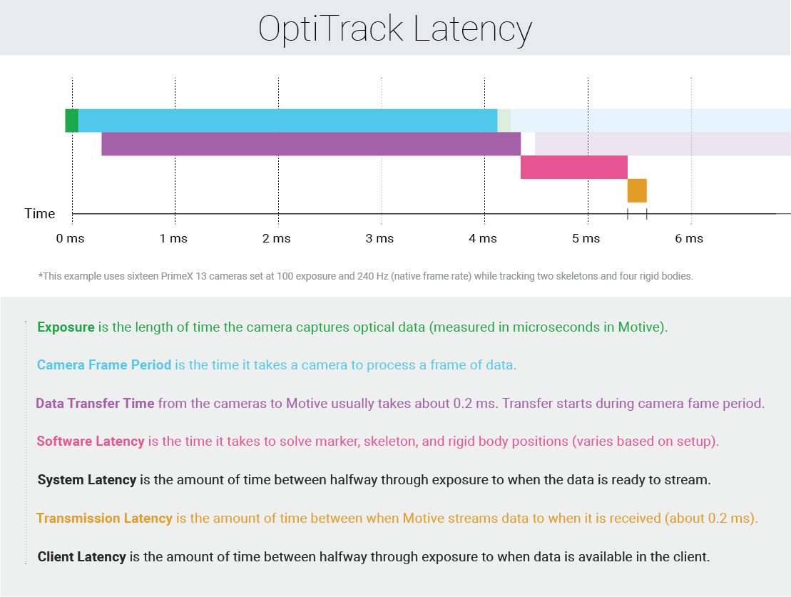
With Motive 3.0+ PrimeX cameras now can go at up to 1000 Hz. In order to do this the image size processes reduces as the frequency goes over the native frame rate for a particular camera. Because less camera data is being process at higher rates, the latency also decreases. The image below shows how the latency changed from the previous image by going from 240 Hz to 500 Hz with PrimeX 13 cameras.
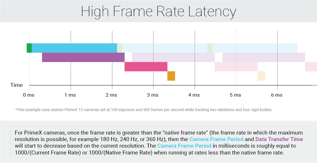
Example frame rates vs the latency added by the camera for a PrimeX 41 camera....

Rate
Camera Latency

20 Hz - 180 Hz

5.56 ms

240 Hz

4.17 ms

360 Hz

2.78 ms

500 Hz

2.00 ms

1000 Hz

1.00 ms

Latency Details
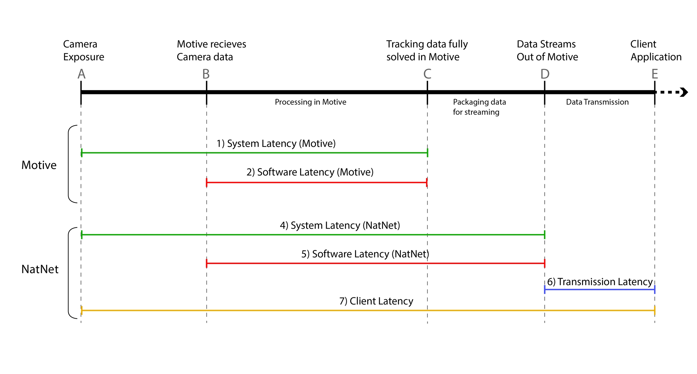
Point
Description

A

This point represents the center of the camera exposure window

B

This is when Motive receives the 2D data from the cameras

C

This is when tracking data is fully solved in Motive.

D

This is when the tracking data is all processed and ready to be streamed out.

E

This is when the Client application receives the streamed tracking data.

In Motive
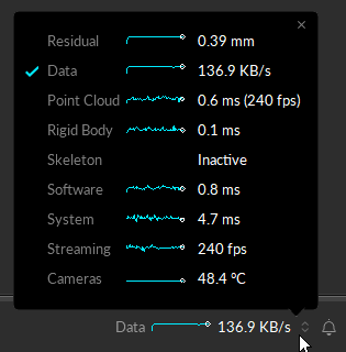
System Latency

  • (Available for Ethernet camera systems only) This value represents current system latency. This is reported under the Status Panel, and it represents the total time taken from when the cameras expose and when the data is fully solved.

Software Latency (Motive)

  • It represents the amount of time it takes Motive to process each frame of captured data. This includes the time taken for reconstructing the 2D data into 3D data, labeling and modeling the trackable assets, displaying in the viewport, and other processes configured in Motive.

Pipeline Specific Latencies

In NatNet

This is available only in NatNet version 3.0 or above.

Exemplary latency calculations are demonstrated in the SampleClient project and the WinFormSample project. Please refer to these sources to find more about how these latency values are derived.

  • Timestamp of Point A: sFrameOfMocapData::CameraMidExposureTimestamp. Available for Ethernet cameras only (Prime / Slim13E).

  • Timestamp of Point B: sFrameOfMocapData::CameraDataReceivedTimestamp.

  • Timestamp of Point D: sFrameOfMocapData::TransmitTimestamp.

System Latency (NatNet)

  • (Available for Ethernet camera systems only)

  • This is the latency introduced by both hardware and software component of the system. This represents the time difference between when the cameras expose and when the capture data is all processed and prepared to be streamed out.

const bool bSystemLatencyAvailable = data->CameraMidExposureTimestamp != 0;

// From SampleClient.cpp (522 ~ 531)
if ( bSystemLatencyAvailable )
{
 
        const uint64_t systemLatencyHostTicks = data->TransmitTimestamp - data->CameraMidExposureTimestamp;
        const double systemLatencyMillisec = (systemLatencyHostTicks * 1000) / static_cast<double>(g_serverDescription.HighResClockFrequency);
}

System Latency may not always be available for all system configurations. Thus, it is suggested to enclose this calculation within a conditional statement.

Software Latency (NatNet)

  • This value needs be derived from the NatNet streaming protocol.

  • This latency value represents the time it takes Motive to process the captured data and have it fully ready to be streamed out. This measurement also covers the data packaging time.

  • This can be derived by subtracting two timestamp values that are reported in NatNet:

// From SampleClient.cpp (502~503)
const uint64_t softwareLatencyHostTicks = data->TransmitTimestamp - data->CameraDataReceivedTimestamp;
const double softwareLatencyMillisec = (softwareLatencyHostTicks * 1000) / static_cast<double>(g_serverDescription.HighResClockFrequency);

In the older versions of NatNet, the software latency was roughly estimated and reported as fLatency data, which is now deprecated. The derived software latency described in this can be used to replace the fLatency values.

Transmission Latency

  • The transmission latency represents the time difference between when Motive streams out the packaged tracking data and when the data reaches the client application(s) through a selected network.

// From SampleClient.cpp (507)
const double transitLatencyMillisec = pClient->SecondsSinceHostTimestamp( data->TransmitTimestamp ) * 1000.0;

Client Latency

  • The client latency is the time difference between when the cameras expose and when the NatNet client applications receive the processed data. This is basically the total time it takes for a client application(s) to receive the tracking data from a mocap system.

// Sample code
const bool bSystemLatencyAvailable = data->CameraMidExposureTimestamp != 0;

if ( bSystemLatencyAvailable )
{
    const double clientLatencyMillisec = pClient->SecondsSinceHostTimestamp(data->CameraMidExposureTimestamp) * 1000.0;
}

Latency in Older Versions

In previous versions of Motive (prior to 2.0), the only reported latency metric was the software latency. This was an estimation of the software latency derived from the sum of the processing times taken from each of the individual solvers in Motive. The latency calculation in Motive 2.0 is a more accurate representation and will be slightly larger by comparison than the latency reported in the older versions.

Troubleshooting

Q: Latency increases when playing media applications on the host PC.

A: When playing media files using applications such as Chrome or VLC, you may experience increased system latency in Motive. This is due to Window's Multimedia Class Scheduler Service (MMCSS). The MMCSS will prioritize CPU resources to these time-sensitive media applications over other applications including Motive. This may cause increased system latency and dropped frames in Motive. We recommend closing media applications if there are any issues with system latency and dropped frames.

This measurement is reported in the in Motive.

This measurement is reported in the in Motive.

Please note that this does not include the time it takes for Motive to convert the solved data into the NatNet streaming protocol format. This conversion accounts for a slight additional latency (≈ 0.2 ms) which is only reflected in the software latency value reported via , therefore resulting in a small delta between the software latency values as reported by Motive and NatNet.

Latencies from the point cloud reconstruction engine, Rigid Body solver, and Skeleton solver are reported individually on the in Motive.

In NatNet 3.0, new data types have been introduced to allow users to monitor measured timestamps from specific points in the pipeline. From received in the NatNet client applications, the following timestamps can be obtained:

Refer to the page or the NatNetTypes.h file for more information

These timestamps are reported in “ticks” that are provided by the host computer clock. When computing latencies, you need to divide the timestamp values by the clock frequency in order to obtain the time values in seconds. The clock frequency is included in the server description packet: sServerDescriptionPacket::HighResClockFrequency. To calculate the time that has elapsed since a specific timestamp, you can simply call the method, passing the desired timestamp as its input. Using clock synchronization between the client and server, this will return the time in seconds since the corresponding timestamp.

This value needs to be derived from the streaming protocol by subtracting two timestamp values that are reported in NatNet:

This value must be derived from the streaming protocol.

This value can be obtained by calling the using sFrameOfMocapData::TransmitTimestamp as the input.

This value must be derived from the streaming protocol.

This value can be obtained by calling the method using sFrameOfMocapData::CameraMidExposureTimestamp as the input.

Status Panel
Status Panel
NatNet SDK 4.0
Status Panel
NatNet:_Data_Types
NatNet SDK 4.0
NatNet SDK 4.0
NatNet SDK 4.0
SecondsSinceHostTimestamp
Status Panel
NatNet SDK 4.0
Status panel in Motive.
NatNetClient::SecondsSinceHostTimestamp
SecondsSinceHostTimestampmethod
sFrameOfMocapData