Information for Assembling the Active Tags
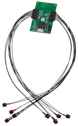
An overview of Active Tags, including power requirements, the type of Pin Out connectors used, and additional details on the IR LEDs.
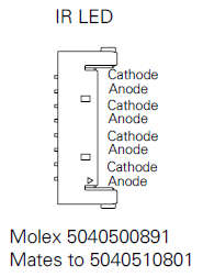
The assembly of the Active Tags and the LEDs are relatively straightforward; connect the wires to the correct cathode/anode terminals using the diagrams, below.

Usage Notes
Battery: Only use batteries that were supplied by OptiTrack.
3.3 - 5.0V inputs for micro and alternate USB connectors.
Recommended to use the LEDs that are provided directly from us.
Other LEDs must work within the following specifications: 1.5 < VLED < 2.5 and ILEDMAX = 100mA
The wires to the LEDs are 30AWG 7 gauge strands.
Pin Out Connector
The following connectors from Molex are used on the Tags to connect the IR LEDs. Please search the corresponding part number on their website for specific information.

IR LEDs
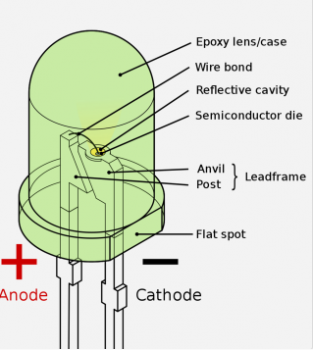
The longer leg on the LED is the cathode of this LED. As shown in the image below, The flat spot can also be referenced to indicate the cathode of this LED. Always remember this flat spot for these black LEDs, and connect the black wire (negative) when using red/black wire pairs.

RevG Tag Alternate Connection Points
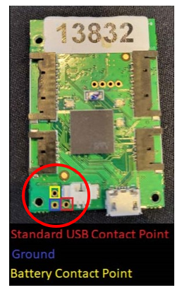
The Active tag has three contact points in the bottom left corner that can be used as an alternative connection point for a power source (Battery or USB).
Warning!
There is risk for short circuit when using these contact points to power the Active Tag. Please proceed with caution if using contact points to power Active Tags.

There are two methods to power the tag using contact points:
Battery
CAUTION!
Do not connect a USB cable to the board while using these pinouts. Doing so poses a risk of short-circuiting and causing damage to the board.
Connect the contact point at the top (highlighted in yellow in the image, above) to the positive terminal of a one-cell, Li-Ion 3.7v battery.
Connect the bottom left contact point (the ground, highlighted in blue, above) to the negative terminal of the battery.
Do not permanently solder the battery to the contact points as the battery cannot be charged (in any manner) while connected to the Active Tag.
USB
Connect the bottom right contact point (highlighted in red, above) to a standard 5V USB source for power.
Connect the USB ground connection to the ground contact point (highlighted in blue, above).
CAUTION!
Do not connect a USB cable to the board while using these pinouts. Doing so poses a risk of short-circuiting and causing damage to the board.
Was this helpful?

