Autodesk MotionBuilder: OptiTrack Optical Plugin
This page provides instructions on how to use the OptiTrack MotionBuilder Optical plugin.
Overview
The OptiTrack Optical Plugin device allows to you to map motion capture (optical) data onto an animated character within MotionBuilder.
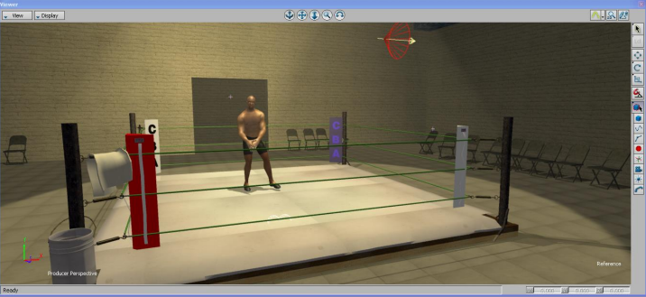
Motive Data Streaming Setup (Server)
First, you'll want to follow the instructions below to set up the data streaming settings in Motive. Once this is configured, Motive will be broadcasting tracking data onto a designated network interface where client applications can receive them.
Streaming Settings
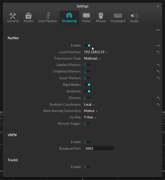
Enable - Turn on the Enable setting at the top of the NatNet section.
Local Interface - Choose the desired IP network address from this dropdown to stream data over.
Loopback
This is the local computer IP address (127.0.0.1 or Localhost).
Used for streaming data locally on the PC you are running Motive on that does not interact with the LAN.
Good option for testing network issues.
192.168.0.1x (typical, but may be different depending on which interface is used to establish a LAN connection)
This IP address is the interface of the LAN either by Wi-Fi or Ethernet.
This will be the same address the Client application will use to connect to Motive.
Transmission Type
For streaming over a Wi-Fi network, setting the Transmission Type to Unicast is strongly advised.
Select desired data types to stream under streaming options:
Rigid Bodies - Enabled (required).
Skeletons - Optional for Skeleton tracking.
Markers (Labeled, Unlabled, Asset) - Disabled for HMDs (advised).
Devices - Disabled.
Skeleton Coordinates
Set to Local.
Bone Naming Convention
When streaming Skeletons, set to FBX.
Additional Tips
For best results, it is advised to run Motive and MotionBuilder separately on different computers, so that they are not competing for processing resources.
When streaming the data over a Wi-Fi network, Unicast transmission must be used.
In order to stream data from the Edit mode, a capture-recording must be playing back in Motive.
For additional information on data streaming in general, read through the Data Streaming page.
MotionBuilder Setup (Client)
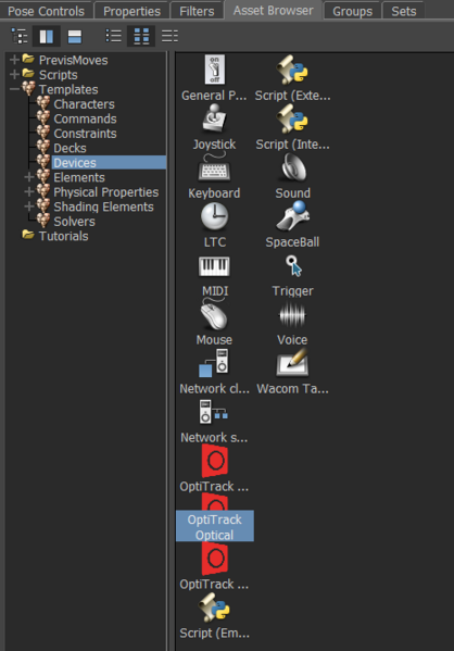
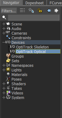
To get started, drag the OptiTrack Optical plugin from the Motion Builder Asset Browser tab > Devices into the Viewer window. This will create a dropdown menu called I/O Devices in the Navigator tab. Click the + button next to I/O Devices and select OptiTrack Optical. This will populate the plugin's settings tab if it hasn't already auto-populated from the drag and drop step from earlier.
Device Settings
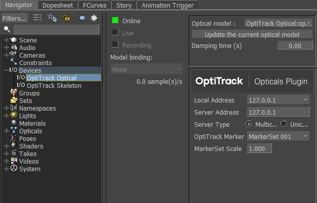
Optical Model
Specified the MotionBuilder "Opticals" model to map the markers to.
Generate a new Optical model/Update the current optical model
Adds/updates the current Marker Set from OptiTrack to list of MotionBuilder "Opticals" model.
Damping Time
Device damping time.
Local address - IP address of the MotionBuilder computer. In situations where multiple network adapter cards are present, select the adapter that is on the same network as the Motive application.
127.0.0.1
This is the local computer IP address (127.0.0.1 or Localhost).
Use this loopback address if Motive is running on the same machine as MotionBuilder.
192.168.0.1x (typical, but may be different depending on which interface is used to establish a LAN connection)
This IP address is the interface of the LAN either by Wi-Fi or Ethernet.
Use this if Motive is running on a different computer, but on the same network as the MotionBuilder computer.
169.xxx.x.xx
This address is assigned when a DHCP server could not be reached.
This address can be ignored for our application.
Server Address - IP address of computer that is running Motive
127.0.0.1
Use this IP when both Motive and MotionBuilder are running on the same computer.
Server Type
Multicast (default) or Unicast
Must match what is selected in the Motive Streaming settings.
Multicast is default and recommended.
OptiTrack Marker Set
The name of the OptiTrack Marker Set this optical device is binding to, required only when using an older version of the MotionBuilder Plugin. Beginning with version 4.2.0, this setting is no longer required and has been removed.
Marker Set Scale
The global scale factor to be applied to the marker data before mapping to the actor.
Once the above settings are input appropriately, you'll want to click the box next to Online. This indicate whether or not Motive is successfully streaming to MotionBuilder.
Online color indicator
Green - Connected and streaming.
Yellow - Connected but not streaming.
Red - Not connected or streaming.
Live
Indicates to MotionBuilder that data is coming from a live source (checked) or from a recorded take.
Recording
Indicates to MotionBuilder that data from this device should be recorded when MotionBuilder is recording.
Model Bindings
Unused.
Device Information
Information about the status of the connection.
Step-By-Step Example
Motive Skeleton Streaming Step-by-step
[Motive]
Configure Motive for Streaming Data
From the Motive Streaming Pane:
Select Enable
Select Bone Naming Convention to FBX. (The plugin device will automatically reconfigure this if not already set to FBX.)
Choose Local Interface IP address from dropdown. If same computer is running both OptiTrack and MotionBuilder use the Loopback option.
Be sure to configure any Firewall software first (either disable or permit MotionBuilder as an exception).
[MoBu]
Create an OptiTrack Optical device
In the MotionBuilder Asset Browser Window > Devices window. You should see:
OptiTrack Optical
Within MotionBuilder, drag the OptiTrack Optical device into the Navigator(or Viewer) pane. An instance will be created under the Devices node.
[MoBu]
Connect Optical Device to Motive
In the Navigator window, select OptiTrack Optical from the Devices node
On the OptiTrack Optical pane, set the IP address of the OptiTrack server (e.g. Motive).
Click on the Online box - it should change from red to yellow (or green if data from the OptiTrack Server is currently streaming).
[MoBu]
Create a Marker Set > Opticals Mapping
In the 'OptiTrack Marker Set' Dropdown, select the name of a currently defined Marker Set in Motive. You may need to resize the device pane in MotionBuilder to access the features.
Press the Generate new optical model button
In the Navigator window, under the Opticals node, you should see a new the marker list. This indicates the plugin has successfully retrieved the marker list from the OptiTrack server. You should also see the Opticals displayed in the Viewer window if the Server is currently streaming.
[MoBu]
Begin streaming marker data
From Motive, start live capture or data playback
From MotionBuilder, ensure the Viewer window is active (MotionBuilder will not update otherwise).
The marker set should be animating in the MotionBuilder Viewer window.
The MotionBuilder Online check boxes should be green, indicating data is live and actively streaming.
Recording Optical Data
The OptiTrack Optical device can record streamed optical data to the current MotionBuilder take. Note that the looping feature in Motive must be disabled in order to record streamed data in MotionBuilder. The following step-by-step procedure can be used to record data:
Recording Optical Data Step-by-step
Enable Optical Device for recording
[Mobu] > Optical > Check Recording
Start Recording
[Mobu] > Transport Control > Record (Create new take)
[Mobu] > Transport Control > Play ( start recording frames)
[Mobu] > Transport Control > Stop
Playing Back Recorded Data
The OptiTrack Optical device can be used to show live data or blend live data with a recorded take. To playback recorded optical data, you need to tell MotionBuilder to disable live streaming.
Playing Back Recorded Data Step-by-step
Disable Live streaming
[Mobu] > Optical > Uncheck Recording
[Mobu] > Optical > Uncheck Live
Playback recorded take
[Mobu] > Transport Control > Rewind
[Mobu] > Transport Control > Play
Generating an optical model while the recording option is enabled will disable recording so the markers can generate correctly.
Re-enable the recording option after the model is done to resume recording.

Optical Data Namespace
When the opticals are generated, their naming conventions will be determined depending on whether the Organize Assets option was enabled under the Optical Device properties.
Organize Assests Enabled (default)
The device will generate optical data with colon ( : ) separator (e.g. AssetName:MarkerName), and all of the optical data will be organized under their corresponding root nodes.
Organize Assets Disabled
The device will generate optical data with an underscore ( _ ) (e.g. AssetName_MarkerName) and all of the optical data will be listed under a same optical node.
For auto-mapping imported FBX actors to optical data, the Organize Assets setting must be disabled and underscore separators must be used.


MotionBuilder Actor/Character Setup
The following guide is provided as a simplified process for working specifically with Motive, but this is not the only way. For the latest information on setting up and configuring MotionBuilder Actors and Characters, please refer to the MotionBuilder documentation.
To animate characters in MotionBuilder, you need to create the following data flow (or “mapping”):
Mocap Marker Data > MotionBuilder “Actor” > Skeleton Data > MotionBuilder “Character”
The Mocap Marker Data > MotionBuilder Actor step maps Motion Capture data (Markers) to the MotionBuilder Actor object. The MotionBuilder Actor object is a Skeleton solver that creates joint angles from Marker data.
The MotionBuilder “Actor” > Skeleton Data > MotionBuilder “Character” step is specific to MotionBuilder, and this pipeline maps the MotionBuilder Actor Skeleton onto your final character Skeleton. This step requires a “rigged” character. Refer to the MotionBuilder help for detailed information on this process.
Actor Setup (Mocap Marker Data > MotionBuilder "Actor")
There are 3 ways to create a Motive Marker Sets > MobBu Actor mapping.
Create a new marker map from scratch.
Import an existing marker map from a file.
Auto-create an actor from the Motive stream.
Create a new marker map from scratch
Create OptiTrack Optical device
Connect to Motive
Generate Opticals
Stream a frame of T-Pose data from Motive
You should see the Opticals in the MotionBuilder 3D viewer
Create MB Actor
Fit MB Actor to Opticals
Create an Optical > Marker Set > Actor mapping:
Import existing mapping
Actor > Marker Set > Import > OptiTrack HIK file
Drag all opticals (incl root) onto Actor’s “Reference Cell”
Create a new mapping:
Actor > Marker Set > Create
Drag individual opticals to Actor segments
Activate Actor (Actor > Activate)
Actor snaps to marker cloud pose
Actor should now be animating in Viewer
Import Existing Marker Map (from File)
Restore Marker Set from HIK file:
[MoBu] Import Marker Set definition (.hik file)
[MoBu] Connect to Motive
[MoBu] Generate Opticals
[Motive] Stream a T-Pose frame of data into MotionBuilder
[MoBu] Actor Panel : Drag Opticals to Actor Markers (Actor Prop Sheet > Reference)
[MoBu] Activate Actor (Actor > Activate)
Actor snaps to marker cloud pose
Actor should now be animating in Viewer
Auto-Create from Stream
The Optitrack MotionBuilder plugin can generate a MoBU Actor for you automatically.
Set the “Create Actors” property to true before bringing the Optical device online.
The Optitrack Mobu plugin will generate an Actor for each Marker Set in the Motive data stream, and correctly map the Motive Marker Set markers to the corresponding Mobu Actor.
Offline Workflow with Actor Binding
In order to workaround Autodesk's removal of support for FBX actor import, we recommend the following:
[Motive] Load a TAK file with desired assets
[Mobu] Use Optical Device to Create Actors over stream from TAK file.
[Motive] Export TAK data from Motive (FBX or C3D)
[Mobu] Import C3D/FBX into Mobu
[Mobu] Update Actor binding to imported C3D / FBX
Character Setup (MotionBuilder Actor > Character)
Do Actor Setup (Above)
Import a rigged Skeleton (File -> Merge -> Skeleton)
If Skeleton is not “characterized, characterize it:
Create MB Character (Drag onto Skeleton “hips” )
Map Character to Actor
Select Character -> Character Settings -> Input Type -> Actor Input
Check “Active”
Activate Actor (Actor -> Activate)
Skeleton and Actor should now be animating in Viewer
For more information on setting up and configuring MotionBuilder Actors and Characters, please refer to Autodesk's MotionBuilder documentation.
Unlabled Markers
Unlabeled markers are not commonly needed in the MotionBuilder workflow, but if needed, they can get streamed through the Optical Device plugin.
[Motive] Make sure streaming of unlabeled markers is enabled in Motive’s data streaming panel.
[MoBu] Under the properties of the Optical Device loaded in the scene, make sure Using Unlabeled Markers option is enabled and the Unlabeled Marker Limit is set to the maximum number of unlabeled makers allowed in the scene.
[MoBu] In Optical Devices, generate or update the optical model.
[MoBu] Unlabeled markers will show up as orange opticals in the scene.
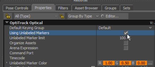
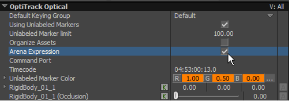
The Optical Device has a special property for Arena Expression ( viewable from the MotionBuilder Properties tab) that must be checked when using with Arena Expression software:
Was this helpful?

