LogoLogo
WebsiteSupportDownloadsForumsQuick LinksContact Us
v3.2
v3.2
  • OptiTrack Documentation
  • WHAT'S NEW
    • What's New in Motive 3.2
  • QUICK START GUIDES
    • Quick Start Guide: Getting Started
    • Quick Start Guide: Prime Color Camera Setup
    • Quick Start Guide: Precision Capture
    • Quick Start Guide: Tutorial Videos
    • Quick Start Guide: Active Marker Tracking
    • Quick Start Guide: Outdoor Tracking Setup
  • HARDWARE
    • Cameras
      • Ethernet Cameras
        • PrimeX 120
        • PrimeX 41
        • PrimeX 22
        • PrimeX 13
        • PrimeX 13W
        • SlimX 13
        • Prime Color
        • VersaX 22
        • VersaX 41
        • VersaX 120
      • USB Cameras
        • Slim 3U
        • Flex 13
        • Flex 3
        • V120:Duo
        • V120:Trio
        • Adjusting Global Origin for Tracking Bars
    • Prepare Setup Area
    • Camera Mount Structures
    • Camera Placement
    • Ethernet Camera Network Setup
      • General Overview and Specs
      • Windows 10 Network Settings
      • Cabling and Load Balancing
      • Switch Configuration for PrimeX 120
      • NETGEAR ProSafe GSM7228S: Disabling the Broadcast Storm Control
      • White/Blacklisting Cameras
    • USB Camera System Setup
      • USB Camera Network Overview and Specs
      • V120:Duo and Trio Setup
      • Tracking Bar Coordinate System
        • Transforming Coordinate System: Global to Local
    • Aiming and Focusing
    • Camera Status Indicators
  • MOTIVE
    • Installation and License Activation
    • Motive Basics
    • Calibration
      • .mcal XML Calibration Files
      • Continuous Calibration
      • Continuous Calibration (Info Pane)
      • Calibration Squares
    • Markers
    • Assets
      • Gizmo Tool: Translate, Rotate, and Scale
    • Rigid Body Tracking
      • Aligning Rigid Body Pivot Point with a Replicated 3D Model
    • Skeleton Tracking
    • Trained Markersets
    • IMU Sensor Fusion
    • Data Recording
      • Data Types
    • Labeling
    • Data Editing
    • Data Export
      • Data Export: BVH
      • Data Export: C3D
      • Data Export: CSV
      • Data Export: FBX
      • Data Export: TRC
    • Data Streaming
    • Camera Video Types
    • Audio Recording
    • Motive HotKeys
    • Measurement Probe Kit Guide
    • Motive Batch Processor
    • Reconstruction and 2D Mode
  • MOTIVE UI PANES
    • Settings
      • Settings: General
      • Settings: Assets
      • Settings: Live Pipeline
      • Settings: Streaming
      • Settings: Views
      • Settings: Mouse and Keyboard
      • Settings: Audio
    • Assets Pane
    • Builder Pane
    • Constraints Pane
      • Constraints XML Files
    • Calibration Pane
    • Data Pane
    • Devices Pane
    • Edit Tools Pane
    • Graph View Pane
    • Info Pane
    • Labels Pane
    • Log Pane
    • Probe Pane
    • Properties Pane
      • Properties Pane: Camera
      • Properties Pane: Force Plates
      • Properties Pane: NI-DAQ
      • Properties Pane: OptiHub2
      • Properties Pane: Rigid Body
      • Properties Pane: Skeleton
      • Properties Pane: Take
      • Properties Pane: Trained Markerset
      • Properties Pane: eSync2
    • Status Panel
    • Toolbar/Command Bar
    • Control Deck
    • Viewport
  • PLUGINS
    • OptiTrack Blender Plugin
      • OptiTrack Blender Plugin
    • OptiTrack Unreal Engine Plugin
      • Unreal Engine: OptiTrack Live Link Plugin
        • Quick Start Guide: Real-Time Retargeting in Unreal Engine with Live Link Content
        • Unreal Editor for Fortnite (UEFN): OptiTrack Plugin for Live Link Hub
        • Unreal Engine: Live Link Camera Stream Setup
        • Live Link Content: Active Puck Static Meshes
      • Unreal Engine: MotionBuilder Workflow
      • Unreal Engine: HMD Setup
      • Unreal Engine VCS Inputs
    • OptiTrack Unity Plugin
      • Unity: HMD Setup
    • OptiTrack OpenVR Driver
    • OptiTrack MATLAB Plugin
    • Autodesk Maya
      • Autodesk Maya: OptiTrack Insight VCS Plugin
    • Autodesk MotionBuilder
      • Autodesk MotionBuilder Plugin
      • Autodesk MotionBuilder: OptiTrack Skeleton Plugin
      • Autodesk MotionBuilder: OptiTrack Optical Plugin
      • Autodesk MotionBuilder: OptiTrack Insight VCS Plugin
      • Autodesk MotionBuilder: Timecode Data
    • OptiTrack Peripheral API
    • External Plugins
      • Houdini 19 Integration
  • ACTIVE COMPONENTS
    • Active Components Hardware
      • Active Puck
      • Wired AnchorPuck
      • CinePuck
      • Wired CinePuck
      • BaseStation
      • Information for Assembling the Active Tags
      • Manus Glove Setup
    • Configuration
      • Active Batch Programmer
      • Active Hardware Configuration: PuTTY
      • Active Component Firmware Compatibility
    • Active Marker Tracking
      • Active Finger Marker Set
  • SYNCHRONIZATION
    • Synchronization Hardware
      • External Device Sync Guide: eSync 2
      • External Device Sync Guide: OptiHub2
    • Synchronization Setup
    • OptiTrack Timecode
  • VIRTUAL PRODUCTION
    • Unreal Engine: OptiTrack InCamera VFX
    • Entertainment Marker Sets
    • PrimeX 41
  • MOVEMENT SCIENCES
    • Movement Sciences Hardware
      • General Motive Force Plate Setup
      • AMTI Force Plate Setup
      • Bertec Force Plate Setup
      • Kistler Force Plate Setup
      • Delsys EMG Setup
      • NI-DAQ Setup
      • Multiple Device Setup
    • Movement Sciences Marker Sets
      • Biomechanics Marker Sets
      • Biomech (57)
      • Rizzoli Marker Sets
    • For Visual3D Users
    • Prime Color Camera Setup
      • Prime Color Setup: Required Components
      • Prime Color Setup: Hardware Setup
      • Prime Color Camera Setup: Camera Settings
      • Prime Color Camera Setup: Prime Color FS Calibration
      • Prime Color Setup: Data Recording / Export
      • Prime Color Camera Setup: FAQ / Troubleshooting
      • Prime Color Camera Setup: Windows Network Settings
  • VIRTUAL REALITY
    • VR Plugins
      • VR Unreal Engine
        • OptiTrack Unreal Engine Plugin
        • Unreal Engine: OptiTrack Live Link Plugin
          • UE5.1 Live Link Retarget External Workaround
        • Unreal Engine VCS Inputs
      • VR Unity
        • OptiTrack Unity Plugin
      • VR OpenVR
        • OptiTrack OpenVR Driver
    • VR HMD Setup
      • Unreal Engine: HMD Setup
      • Unity: HMD Setup
      • Manually Calibrating the HMD Pivot Point
      • Sync Configuration with an HTC Vive System
    • SlimX 13
    • Active Marker Tracking
      • Active Finger Marker Set
    • Synchronization Hardware
      • External Device Sync Guide: eSync 2
      • External Device Sync Guide: OptiHub2
  • ANIMATION
    • Autodesk Maya
      • Autodesk Maya: OptiTrack Insight VCS Plugin
    • Autodesk MotionBuilder
      • Autodesk MotionBuilder Plugin
      • Autodesk MotionBuilder: OptiTrack Skeleton Plugin
      • Autodesk MotionBuilder: OptiTrack Optical Plugin
      • Autodesk MotionBuilder: OptiTrack Insight VCS Plugin
      • Autodesk MotionBuilder: Timecode Data
  • ROBOTICS
    • MoCap4ROS2 Setup
    • OptiTrack Robot Applications
    • Outdoor Tracking Setup
  • DEVELOPER TOOLS
    • Developer Tools Overview
    • Camera SDK
      • Class: cCameraModule
      • Class: cUID
    • Motive API
      • Motive API: Quick Start Guide
      • Motive API Overview
      • Motive API: Function Reference
      • Motive API Camera Calibration
    • NatNet SDK
      • NatNet 4.1
      • NatNet: Class/Function Reference
      • NatNet: Creating a Managed (C sharp) Client Application
      • NatNet: Creating a Native (C++) Client Application
      • NatNet: Data Types
      • NatNet: Matlab Wrapper
      • NatNet: Migration to NatNet 3.0 libraries
      • NatNet: Remote Requests/Commands
      • NatNet: Sample Projects
      • NatNet: Unicast Data Subscription Commands
      • Latency Measurements
    • VRPN Sample
    • Peripheral API: Glove Devices
  • SKELETON MARKER SETS
    • Full Body
      • Baseline (41)
      • Core (50)
      • Biomech (57)
      • Conventional (39)
    • Full Body + Fingers
      • Baseline + Passive Fingers (49)
      • Baseline + Active Fingers (57)
      • Core + Passive Fingers (54)
      • Core + Active Fingers (62)
    • Upper
      • Baseline Upper (25)
      • Conventional Upper (27)
    • Lower
      • Baseline Lower (20)
      • Helen Hayes Lower (19)
      • Conventional Lower (16)
    • Hand and Fingers
      • Left/Right Hand (4) Active
      • Left/Right Hand (10) Active + Passive
      • Active Finger Marker Set
    • Glove Device Setup
      • Manus Glove Setup
      • StretchSense Glove Setup
    • Rizzoli Marker Sets
    • Entertainment Marker Sets
    • Rigid Body Skeleton Marker Set
  • GENERAL TROUBLESHOOTING
    • Licensing Troubleshooting
    • Windows 11 Optimization for Realtime Applications
    • Network Troubleshooting
    • Troubleshooting Q&A
    • Running Motive on High DPI Displays
    • Firewall Settings
Powered by GitBook
On this page

Was this helpful?

Export as PDF
  1. VIRTUAL REALITY
  2. VR Plugins
  3. VR Unreal Engine

Unreal Engine VCS Inputs

PreviousUE5.1 Live Link Retarget External WorkaroundNextVR Unity

Was this helpful?

This page provides instructions on how to configure VCS inputs in Unreal Engine. The basic configuration is similar to configuring any other input triggers in Unreal Engine. Please note that only one VCS controller can be connected and configured due to some limitations. Having two controllers connected at the same time is not supported.

Setup Steps

Create VCS Rigid Body in Motive

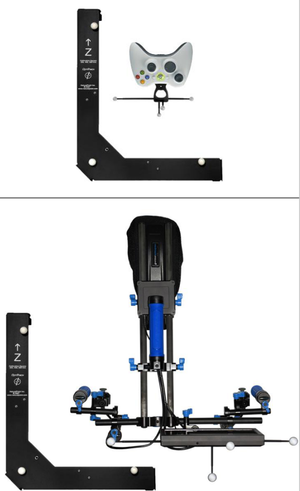
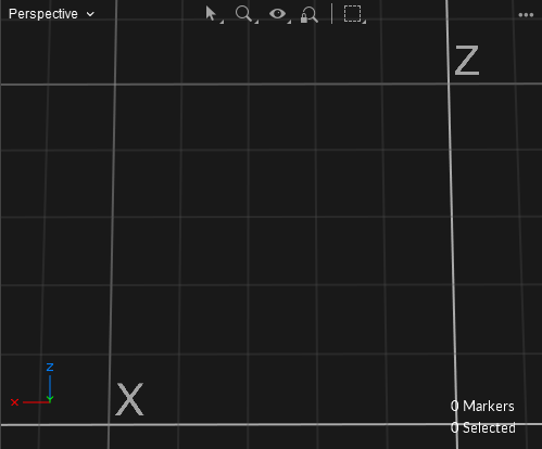
Create a Rigid Body from your tracking controller’s markers using the Builder pane or by selecting the markers and using the keyboard hotkey CTRL + T. You'll want to orient the controller along the +Z axis during creation to define the 'neutral' or 'zero' orientation.

Orientation of VCS in the physical space.

Configure Data Streaming settings

Create/load an UE Project

Start up a project in Unreal Engine (UE).

Enable Windows RawInput plugin

Go to Edit tab → Plugins to open the plugins panel. Enable the Windows RawInput plugin under the Input Devices group.

Connect VCS plugin through the enabled plugin

In Edit tab → Project Settings, scroll to the bottom on the left side panel until you see Raw Input under the plugins group. Here you will let UE project know which input devices to use.

Find Hardware ID and Product ID of the VCS controllers

To find these IDs, you will need to look at the windows device properties. Go to Windows Control Panel -> Devices and Printers. Then right-click on the VCS controllers to access its properties. In the properties, go to the Hardware tab and click properties for “HID-compliant game controller”.

Once you access the controller properties, go to the details tab. Select Hardware ID in the drop-down menu and the hardware ID (HID) and product ID (PID) will be shown under the highlighted section.

Input the IDs in UE

Under the project settings panel Raw Input plugin properties, input both the vendor ID (Hardware ID) and the product ID (PID) that was found under the controller properties.

Register the Input Buttons

Now the project has the IDs to look for the controllers, next step is to setup and register the input buttons. To do so, you will play the project scene, and trigger on the buttons to register them.

In UE, hit Play and press (~) to access the console. In the console, input command ShowDebug INPUT". This will list out all of the input actions on the left side of the viewport.

Use the keys to register

Use all of the keys on the controller to register the inputs; total three axis and seven buttons. Please note that these keys may not exactly match the keys on your controller.

  • Axis 1: Joystick left/right

  • Axis 2: Joystick up/down

  • Axis 3: Nob rotate

  • Button 1: Blue

  • Button 2: Black

  • Button 3: White

  • Button 4: Red

  • Button 6: Joystick click

  • Button 7: Nob click

Map the Registered Inputs

Now that the buttons have been registered, next step is to map the keys. They will be mapped under Edit → Project Settings → Inputs. Choose either the Axis mapping or the action mapping to map the controls to desired actions.

Use the Registered Inputs

Now that all of the buttons are set up, use them to control the VCS in UE.

Line up the controller with the Z axis in Motive to mimic the orientation in the physical space.

In Motive, configure the data streaming settings. Use the pane to configure streamed packets. Make sure Rigid Body data is streamed out in order to use VCS.

Data Streaming