Unreal Engine: Using the OptiTrack Streaming Client Plugin
Instructions to set up and use the OptiTrack Streaming Client Unreal Engine plugin.
The Unreal Engine plugin is intended for Virtual Reality customers, but can be used with many other applications. This page covers the use of the plugin. For more information about the plugin and related Motive settings, please see the OptiTrack Unreal Engine Plugin page.
Streaming Client Setup (Client)
The first step is to configure the client to receive the streamed tracking data.
Enable the Plugin
OptiTrack - Streaming Client Plugin (required)
Download the plugin from the OptiTrack Plugins download page and extract all files.
Open the extracted folder and transfer the entire "OptiTrack" folder into Unreal Engine's plugin directory located at
C:\Program Files\Epic Games\UE_5.#\Engine\Plugins.There will be other plugins in that folder already.Open/Create a new Unreal Engine project.
Under the Edit menu, click Plugins to open the panel to see all available plugins.
Browse to the OptiTrack section and enable the "OptiTrack - Streaming Client."
Click Apply to submit the changes. This will require the Unreal Engine project to be restarted.
Set up the Client Origin
Once the OptiTrack - Streaming Client plugin is enabled, the OptiTrack Client Origin actor will be available in Unreal Engine.
OptiTrack Client Origin
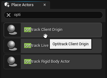
OptiTrack Client Origin
The OptiTrack Client Origin class enables the Unreal Engine (client) to communicate with the Rigid Body, Skeleton, and HMD tracking data streamed from Motive.
To add the client origin, simply drag-and-drop the OptiTrack Client Origin from the Place Actors panel into the level. Once the client origin is placed within the level, its position and orientation will reconcile the global origin of Motive in Unreal Engine. In other words, the tracking data will be represented relative to where this Client Origin object is positioned and oriented.
Global Origin: Both position and orientation of the OptiTrackClientOrigin will represent the global origin of the tracking volume within Motive.
Connecting Unreal Engine to Motive
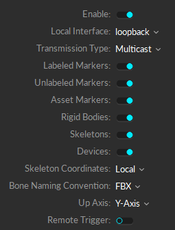
[Motive] Make sure that NatNet streaming is enabled in the Streaming Pane in Motive.
[Unreal] Once the plugin is added and enabled in the project, the OptiTrack Client Origin class will be available from the Place Actors panel.
[Unreal] Drag and drop the OptiTrack Client Origin into the scene.
[Unreal] Place the OptiTrack Client Origin at the desired location within the scene.
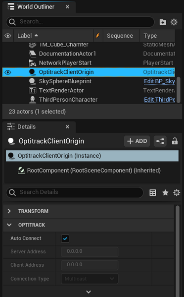
[Unreal] Select the instantiated OptiTrackClientOrigin object from the World Outliner panel.
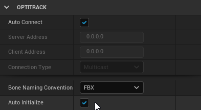
[Unreal] In the Details panel, make sure its Auto Connect setting is checked. This configures the client origin to automatically search the network and connect to Motive.
Now that the client origin is set, the client origin will attempt to connect to Motive and start receiving the tracking data whenever the scene is played.
Connecting to a designated IP address
If you wish to connect to a server on a specific network address, you can uncheck the Auto Connect setting and manually enter the Server IP Address chosen in the Streaming Pane in Motive, Client IP Address, and Connection Type associated with Motive. You may need to run the ipconfig command in the command prompt to obtain an appropriate IP address of the client.
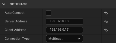
Advance settings: Auto-initialize
By default, the auto-initialize feature is enabled and the client origin will get auto-initialized whenever the scene is played. But when needed, you can disable this and set up the project so the client origin gets initialized when a user-defined event is triggered.
Animate Rigid Bodies
OptiTrack Rigid Body Actor
Actor objects in Unreal Engine can be animated using Rigid Body tracking data from Motive. Once the OptiTrack - Streaming Client plugin is enabled in the project, OptiTrack Rigid Body component will be available to use. By attaching this component onto an actor, you can animate its child actors according to the movement of a Rigid Body in Motive. Each Rigid Body component is given a Tracking ID value which associates with the Streaming ID of a Rigid Body in Motive. Once associated, the data from the corresponding Rigid Body will be used to update the transform of the target actor in Unreal Engine.
Set Up Steps
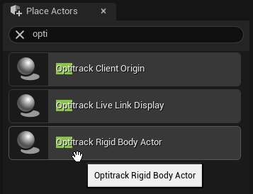
[Unreal] From the Place Actors panel, search for OptiTrack Rigid Body Actor, then drag-and-drop the actor into the scene.
[Unreal] With this Rigid Body actor selected, attach the target actor that you wish to animate using the Details panel. Make sure the target actor's transformation is set to movable.
[Unreal] Set the relative locations and rotations to all zeroes on this target actor. This actor should be listed as a child of the Rigid Body actor.
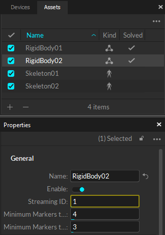
[Motive] In Motive, assign a value to Streaming ID property for the target Rigid Body.
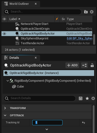
[Unreal] In the properties of the OptiTrack Rigid Body Actor component, match the Tracking ID with the Streaming ID of the Rigid Body asset in Motive.
Make sure both Motive and OptiTrack Client Origin is set up for streaming, hit Play, and the attached actor object will be animated according to the live-streamed Rigid Body tracking data.
RigidBodyComponent Properties
Tracking ID
ID of the Rigid Body used to derive the position and orientatation transform of the attached actor. This ID must match with the Streaming ID of the respective Rigid Body in Motive.
Hide on Invalid Definition
When this is checked, the corresponding Rigid Body actor will be hidden from the level until the associated Rigid Body data is streamed out from Motive and received by the plugin.
Disable Low Latency Update
Low latency update feature allows Rigid Body position and orientation transform to be updated immediately before rendering minimizing the latency. This is enabled by default. For debugging, you can check this setting to disable this behavior.
Tracking Origin
This sets a specific client origin to use for receiving tracking data. When this is unset, the plugin will default to the first client origin that it finds in the scene.
Respect Parent Transform
When this is set to true, the Rigid Body transform data from Motive will be applied in respect to the parent actor's pivot coordinates. By default, this is set to false, and all of the tracking data will be applied in respect to the pivot axis of the client origin.
Drawing Markers
When needed, you can also draw labeled marker data from Motive into the scene in UE. In most applications, you do not have to draw the markers as Rigid Body data and the Skeleton data will be used instead; however, getting markers generated in the scene may be helpful for debugging purposes. To enable drawing of the markers:
[UE4] Expand the OptiTrackClientOrigin (Instance) properties, and enable the Draw Markers checkbox.
[Motive] Labeled Markers setting in the data streaming pane must be enabled.
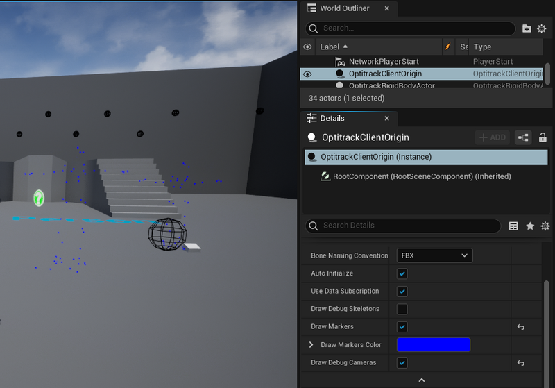
Animate Skeletons
Skeleton streaming is supported only in plugin versions 1.9 or above.
Tutorial Video
Setup
Follow the below steps to set up Skeleton streaming onto Unreal Engine.
1. Create a Animation Blueprint in the 3D View
Step 1. Navigate to a character folder. With Paragon sample characters, it is located in Characters → Heros → [Character Name] → Meshes.
Step 2. Right-click the blank space in the Content Browser pane, then select Animation → Animation Blueprint.
Step 3. On the pop-up window, select the OptiTrackAnimInstance at the parent class section at the top and click on the target Skeleton name at the bottom. Then click OK.
Step 4. In the content browser, assign a name to the created animation blueprint.
Step 5. Drag the character blueprint into the scene.
Step 6. Select the character blueprint in the 3D View
In the Details Pane, select “+ ADD” and create a new an “OptiTrack Skeleton Instance” on the model.
Set the “Source Skeleton Asset” equal to the Skeleton name in Motive.
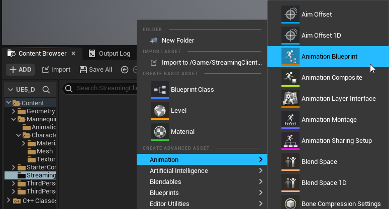
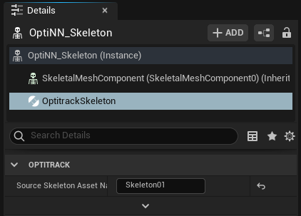
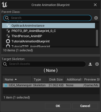
2. Setup the Blueprint
**Step 1.**Double-click the animation blueprint in the content browser to open its editor.
**Step 2.**Right-click the animation graph, then create a new "OptiTrack Skeleton".
**Step 3.**Right-click the animation graph, then create a new "Get Streaming Client Origin" and connect its output to the Streaming Client Origin.
**Step 4.**Right-click the animation graph, then create a new "Get Source Skeleton Asset Name" and connect its output to the Source Skeleton Asset Name.
Step 5. Right-click the animation graph, then create a new "Component To Local" and connect the output from "OptiTrack Skeleton" into its input.
**Step 6.**Connect all of the nodes together. The basic animation flow chart should look like the following.

Bone Transformation
Within the animation blueprint, you can utilize other blueprint utility tools from UE4 to modify the streamed data. For example, Transform (Modify) Bone nodes can be included after the OptiTrack Skeleton node to apply a transform to specific Skeleton bones as needed. Please refer to Unreal Engine documentation for more information on using animation blueprints.
Roll Bone Interpolation
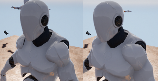
For characters with unmapped shoulder roll bones, the Skeleton plugin will detect its existence and apply a slight twist to the roll bones to keep smooth swinging motion on the arms. In the OptiTrack Skeleton blueprint, you can enable/disable this feature from the Roll Bone Interpolation checkbox, and you can also adjust how much of twist is applied by setting the Roll Bone Blending parameter. When this parameter is set to 0, the plugin will not adjust the roll bone motion, and when this is set to 1, the plugin will attempt to adjust its motion to keep the shoulder steady on the character.
Please note that this feature may not work on some characters.
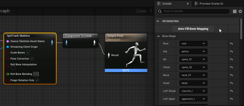
3. Assign Bone Mapping
Step 1. Select the OptiTrack Skeleton plugin in the blueprint graph area.
Step 2. Drop down the Bone Mappings property in the Details Pane.
Step 3. Click “Auto Fill Bone Mapping” to automatically assign the bones in the Skeleton to the OptiTrack Skeleton names.
Note: There is no standard for bone naming conventions, so bone names may vary depending on characters. After doing the auto-fill, review the list and double-check that the auto-assigned names are correct. You may need to manually use the drop-down menu to adjust the assigned mapping for missing, or incorrect, items.
Step 4. Hit "Compile" in the top left to build the blueprint.
4. Setup OptiTrack Streaming
Step 1. Open the 3D View
Step 2. Search OptiTrack Client Origin in the Modes pane.
Step 3. Drag the OptiTrack Client Origin into the 3D scene, then select it to access its properties.
(Optional) put it at 0,0,0 location.
Make sure that streaming settings on both Motive and Unreal match.
See: OptiTrack Unreal Engine page for more instructions on setting up the client origin.
5. Click _Play_
Notes on bone mapping
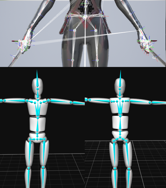
The OptiTrack Unreal Engine Skeleton Plugin uses bone mapping, not retargeting. This means that the bone segments in Motive map directly to the character model (bone mapping), instead of being translated into something that is usable by a more abstract biped model (retargeting). Because of this non-anatomical Skeletons will not map correctly without some additional tweaking.
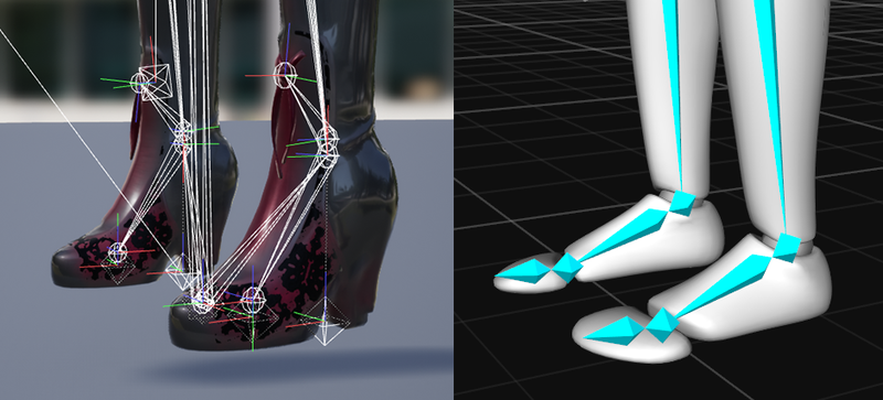
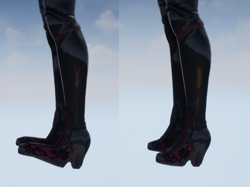
Practically, this means that you will need to do things like turn off the toe mapping for characters with high heels, adjusting the pelvis bone in Motive or in the model for characters with non-anatomical hip bones, and not use bipeds that are too anatomically different than humans, such as a gorilla or swamp monster.
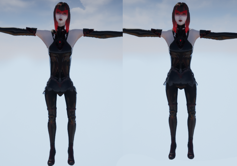
For example, the character sample below has both a non-anatomical pelvis and high heels. It is preferable to use character models that are more anatomically correct, but in this case, you can do a couple things to mitigate these issues:
1. Turn-off toe streaming
In the example below, since this character is wearing heels, any actor providing data for this model will also need to be wearing heels. To get around this you can just turn off the toe mapping in the OptiTrack Unreal Engine Skeleton Plugin.
2. Adjust the bone segments in Motive
The hip segment on the Countess actor is centered in the stomach rather than in the pelvis, the neck bone in Motive is a bit too long for the model, and the shoulders in Motive do not match the width of the character’s shoulders. By adjusting bones' positions and lengths in Motive, you can make the streamed Skeleton to better match the model; however, please note that there are limitations to how much you can do this.)
Bone Scaling
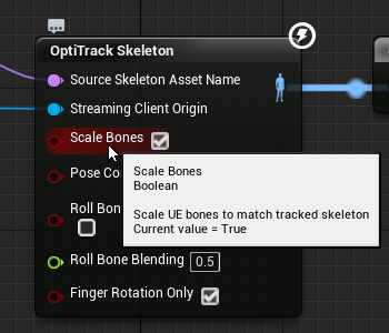
When streaming Skeleton data to animate characters that have different bone lengths compared to the mocap actor, the UE character will need to be scaled accordingly. In this case, the "Scale Bones" feature in the OptiTrack Skeleton node automatically scales the character bones to match the mocap actor. This setting is enabled by default.
Aligning Bones
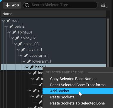
The OptiTrack Unreal Engine Skeleton Plugin uses bone mapping, not retargeting. This means that the bone segments in Motive map directly to the character model (bone mapping), instead of being translated into something that is usable by a more abstract biped model (retargeting). Because of this, non-anatomical Skeletons will not map correctly without some additional tweaking. Starting from plugin version 1.23, you can tweak the alignment of the bone mapping by adding sockets to the Skeleton blueprint:
Adding Sockets to the Bone Mapping
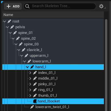
Open Skeleton Editor of the character you wish to modify
Under the Skeleton tree, right-click on the bone that you wish to add the sockets to.
Right click and select_Add Socket_.
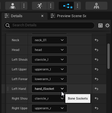
Go to the Animation blueprint, and change the bone mapping of the bone which you have created sockets for, and map it to the socket that was just created.
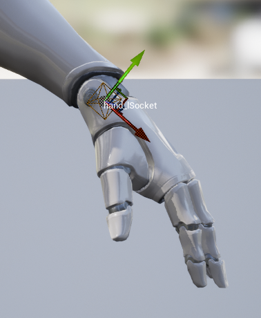
Play the scene, and adjust the socket location from the Skeleton Editor to adjust alignment of the bone.
Last updated
Was this helpful?

