LogoLogo
WebsiteSupportDownloadsForumsQuick LinksContact Us
v3.1
v3.1
  • OptiTrack Documentation
  • WHAT'S NEW
    • What's New in Motive 3.1
  • QUICK START GUIDES
    • Quick Start Guide: Getting Started
    • Quick Start Guide: Prime Color Camera Setup
    • Quick Start Guide: Precision Capture
    • Quick Start Guide: Tutorial Videos
    • Quick Start Guide: Active Marker Tracking
    • Quick Start Guide: Outdoor Tracking Setup
  • HARDWARE
    • Cameras
      • Ethernet Cameras
        • PrimeX 120
        • PrimeX 41
        • PrimeX 22
        • PrimeX 13
        • PrimeX 13W
        • SlimX 13
        • Prime Color
      • USB Cameras
        • Slim 3U
        • Flex 13
        • Flex 3
        • Duo 3
        • Trio 3
        • Adjusting Global Origin for Tracking Bars
    • Prepare Setup Area
    • Camera Mount Structures
    • Camera Placement
    • Ethernet Camera Network Setup
      • General Overview and Specs
      • Windows 10 Network Settings
      • Cabling and Load Balancing
      • Switch Configuration for PrimeX 120
      • NETGEAR ProSafe GSM7228S: Disabling the Broadcast Storm Control
      • White/Blacklisting Cameras
    • USB Camera System Setup
      • USB Camera Network Overview and Specs
      • Duo 3 and Trio 3 Setup
      • Tracking Bar Coordinate System
        • Transforming Coordinate System: Global to Local
    • Aiming and Focusing
    • Camera Status Indicators
  • MOTIVE
    • Installation and License Activation
    • Motive Basics
    • Calibration
      • Continuous Calibration
      • Continuous Calibration (Info Pane)
      • Calibration Squares
    • Markers
    • Assets
      • Gizmo Tool: Translate, Rotate, and Scale
    • Rigid Body Tracking
      • Aligning Rigid Body Pivot Point with a Replicated 3D Model
    • Skeleton Tracking
    • Trained Markersets
    • IMU Sensor Fusion
    • Data Recording
      • Data Types
    • Labeling
    • Data Editing
    • Data Export
      • Data Export: BVH
      • Data Export: C3D
      • Data Export: CSV
      • Data Export: FBX
      • Data Export: TRC
    • Data Streaming
    • Camera Video Types
    • Audio Recording
    • Motive HotKeys
    • Measurement Probe Kit Guide
    • Motive Batch Processor
    • Reconstruction and 2D Mode
  • MOTIVE UI PANES
    • Settings
      • Settings: General
      • Settings: Assets
      • Settings: Live Pipeline
      • Settings: Streaming
      • Settings: Views
      • Settings: Mouse and Keyboard
      • Settings: Audio
    • Assets Pane
    • Builder Pane
    • Constraints Pane
      • Constraints XML Files
    • Calibration Pane
    • Data Pane
    • Devices Pane
    • Edit Tools Pane
    • Graph View Pane
    • Info Pane
    • Labels Pane
    • Log Pane
    • Probe Pane
    • Properties Pane
      • Properties Pane: Camera
      • Properties Pane: Force Plates
      • Properties Pane: NI-DAQ
      • Properties Pane: OptiHub2
      • Properties Pane: Rigid Body
      • Properties Pane: Skeleton
      • Properties Pane: Take
      • Properties Pane: Trained Markerset
      • Properties Pane: eSync2
    • Status Panel
    • Toolbar/Command Bar
    • Control Deck
    • Viewport
  • PLUGINS
    • OptiTrack Blender Plugin
      • OptiTrack Blender Plugin
    • OptiTrack Unreal Engine Plugin
      • Unreal Engine: OptiTrack Streaming Client Plugin
      • Unreal Engine: OptiTrack Live Link Plugin
        • Quick Start Guide: Real-Time Retargeting in Unreal Engine with Live Link Content
        • Unreal Editor for Fortnite (UEFN): OptiTrack Plugin for Live Link Hub
        • Unreal Engine: Live Link Camera Stream Setup
        • Live Link Content: Active Puck Static Meshes
      • Unreal Engine: MotionBuilder Workflow
      • Unreal Engine: HMD Setup
      • Unreal Engine VCS Inputs
    • OptiTrack Unity Plugin
      • Unity: HMD Setup
    • OptiTrack OpenVR Driver
    • Autodesk Maya
      • Autodesk Maya: OptiTrack Insight VCS Plugin
    • Autodesk MotionBuilder
      • Autodesk MotionBuilder Plugin
      • Autodesk MotionBuilder: OptiTrack Skeleton Plugin
      • Autodesk MotionBuilder: OptiTrack Optical Plugin
      • Autodesk MotionBuilder: OptiTrack Insight VCS Plugin
      • Autodesk MotionBuilder: Timecode Data
    • OptiTrack Peripheral API
    • External Plugins
      • Houdini 19 Integration
  • ACTIVE COMPONENTS
    • Active Components Hardware
      • Active Puck
      • CinePuck
      • BaseStation
      • Information for Assembling the Active Tags
      • Manus Glove Setup
    • Configuration
      • Active Batch Programmer
      • Active Hardware Configuration: PuTTY
      • Active Component Firmware Compatibility
    • Active Marker Tracking
      • Active Finger Marker Set
  • SYNCHRONIZATION
    • Synchronization Hardware
      • External Device Sync Guide: eSync 2
      • External Device Sync Guide: OptiHub2
    • Synchronization Setup
    • OptiTrack Timecode
  • VIRTUAL PRODUCTION
    • Unreal Engine: OptiTrack InCamera VFX
    • Entertainment Marker Sets
    • PrimeX 41
  • MOVEMENT SCIENCES
    • Movement Sciences Hardware
      • General Motive Force Plate Setup
      • AMTI Force Plate Setup
      • Bertec Force Plate Setup
      • Kistler Force Plate Setup
      • Delsys EMG Setup
      • NI-DAQ Setup
      • Multiple Device Setup
    • Movement Sciences Marker Sets
      • Biomechanics Marker Sets
      • Biomech (57)
      • Rizzoli Marker Sets
    • For Visual3D Users
    • Prime Color Camera Setup
      • Prime Color Setup: Required Components
      • Prime Color Setup: Hardware Setup
      • Prime Color Camera Setup: Camera Settings
      • Prime Color Camera Setup: Prime Color FS Calibration
      • Prime Color Setup: Data Recording / Export
      • Prime Color Camera Setup: FAQ / Troubleshooting
      • Prime Color Camera Setup: Windows Network Settings
  • VIRTUAL REALITY
    • VR Plugins
      • VR Unreal Engine
        • OptiTrack Unreal Engine Plugin
        • Unreal Engine: OptiTrack Live Link Plugin
          • UE5.1 Live Link Retarget External Workaround
        • Unreal Engine: Using the OptiTrack Streaming Client Plugin
        • Unreal Engine VCS Inputs
      • VR Unity
        • OptiTrack Unity Plugin
      • VR OpenVR
        • OptiTrack OpenVR Driver
    • VR HMD Setup
      • Unreal Engine: HMD Setup
      • Unity: HMD Setup
      • Manually Calibrating the HMD Pivot Point
      • Sync Configuration with an HTC Vive System
    • SlimX 13
    • Active Marker Tracking
      • Active Finger Marker Set
    • Synchronization Hardware
      • External Device Sync Guide: eSync 2
      • External Device Sync Guide: OptiHub2
  • ANIMATION
    • Autodesk Maya
      • Autodesk Maya: OptiTrack Insight VCS Plugin
    • Autodesk MotionBuilder
      • Autodesk MotionBuilder Plugin
      • Autodesk MotionBuilder: OptiTrack Skeleton Plugin
      • Autodesk MotionBuilder: OptiTrack Optical Plugin
      • Autodesk MotionBuilder: OptiTrack Insight VCS Plugin
      • Autodesk MotionBuilder: Timecode Data
  • ROBOTICS
    • MoCap4ROS2 Setup
    • OptiTrack Robot Applications
    • Outdoor Tracking Setup
  • DEVELOPER TOOLS
    • Developer Tools Overview
    • Camera SDK
      • Class: cCameraModule
      • Class: cUID
    • Motive API
      • Motive API: Quick Start Guide
      • Motive API Overview
      • Motive API: Function Reference
      • Motive API Camera Calibration
    • NatNet SDK
      • NatNet 4.1
      • NatNet: Class/Function Reference
      • NatNet: Creating a Managed (C sharp) Client Application
      • NatNet: Creating a Native (C++) Client Application
      • NatNet: Data Types
      • NatNet: Matlab Wrapper
      • NatNet: Migration to NatNet 3.0 libraries
      • NatNet: Remote Requests/Commands
      • NatNet: Sample Projects
      • NatNet: Unicast Data Subscription Commands
      • Latency Measurements
    • Peripheral API: Glove Devices
  • SKELETON MARKER SETS
    • Full Body
      • Baseline (41)
      • Core (50)
      • Biomech (57)
      • Conventional (39)
    • Full Body + Fingers
      • Baseline + Passive Fingers (49)
      • Baseline + Active Fingers (57)
      • Core + Passive Fingers (54)
      • Core + Active Fingers (62)
    • Upper
      • Baseline Upper (25)
      • Conventional Upper (27)
    • Lower
      • Baseline Lower (20)
      • Helen Hayes Lower (19)
      • Conventional Lower (16)
    • Hand and Fingers
      • Left/Right Hand (4) Active
      • Left/Right Hand (10) Active + Passive
      • Active Finger Marker Set
    • Glove Device Setup
      • Manus Glove Setup
      • StretchSense Glove Setup
    • Rizzoli Marker Sets
    • Entertainment Marker Sets
    • Rigid Body Skeleton Marker Set
  • GENERAL TROUBLESHOOTING
    • Licensing Troubleshooting
    • Windows 11 Optimization for Realtime Applications
    • Network Troubleshooting
    • Troubleshooting Q&A
    • Running Motive on High DPI Displays
    • Firewall Settings
Powered by GitBook
On this page
  • BaseStation Specifications
  • BaseStation Load Capacity
  • Configure the BaseStation
  • BaseStation LEDs
  • BaseStations in Motive

Was this helpful?

Export as PDF
  1. ACTIVE COMPONENTS
  2. Active Components Hardware

BaseStation

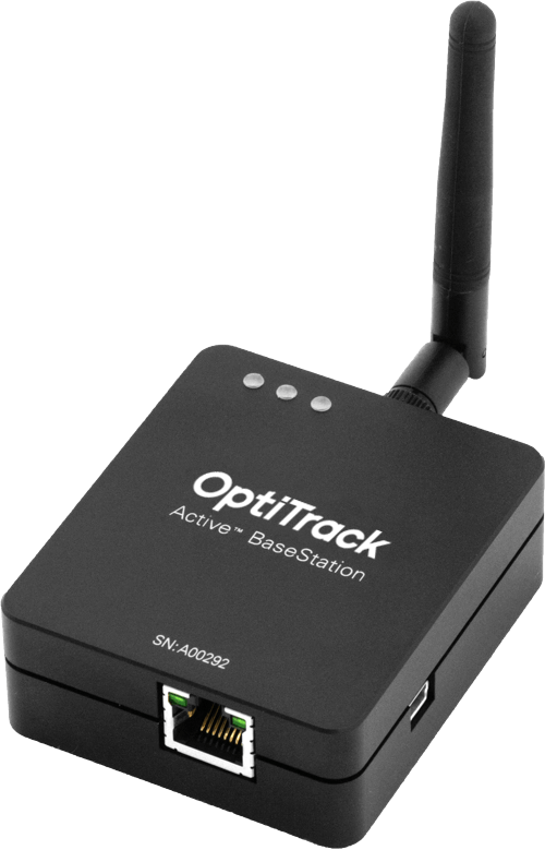
This page provides specifications for BaseStations and information about their use.
PreviousCinePuckNextInformation for Assembling the Active Tags

Last updated 1 year ago

Was this helpful?

The BaseStation is the active hardware component that links other active components to Motive. Using a radio frequency channel (RF channel) between 11-26, the BaseStation synchronizes OptiTrack cameras with Active Tags and Pucks. Once the BaseStation receives the signal from the active component, it sends that data to the Motive computer along the camera network. This allows Motive to recognize Active Pucks and Tags even with significant occlusion of the LED markers, as compared to passive markers.

If you use Active Tags or Pucks, at least one BaseStation is required per tracking system.

For larger volumes, the approximate range from BaseStation to Tags/Pucks is 100’.

BaseStation Specifications

BaseStation Load Capacity

The number of IMUs that can attach to a BaseStation is determined by the system frame rate and the divisor applied to the BaseStation. The table below shows the IMU maximum for common frame rates with a divisor rate of 1, 2, and in some cases 3.

FrameRate
Divisor Rate 1
Divisor Rate 2
Divisor Rate 3

60

26

54

83

70

22

47

71

80

19

39

62

90

16

36

54

100

14

32

49

110

13

29

44

120

11

26

40

130

10

24

140

9

22

34

150

9

20

160

8

19

30

170

7

17

180

7

16

26

190

6

15

200

6

14

23

210

5

14

220

5

13

21

230

5

12

240

4

11

18

250

4

11

  1. Use PuTTy to change the divisor rate on the BaseStation.

  2. Connect an IMU puck to PuTTy.

  3. Attempt to set the ID of the puck to an unrealistically high value. This triggers a warning that includes the current number of slots available for the given frame rate.

  4. Set the IMU puck ID to the highest available slot for the frame rate and confirm that it appears in Motive.

BaseStations have 16 radio frequency (RF) channels available for use (11-26). When adding more than one BaseStation to a system, the IMU count is simply the maximum number of IMUs multiplied by the number of BaseStations (up to 16). For example, in a system with 4 BaseStations running at 90Hz and a divisor rate of 3, the number of allowable IMUs would be 216 (54*4=216).

Configure the BaseStation

As shipped, BaseStations will connect to the OptiTrack system without additional configuration by the user. Some circumstances may require a configuration update, such as when adding new BaseStations to an existing system or when you wish to change the divisor rate.

The BaseStation is configured outside of Motive, using one of the following programs:

Please see the linked pages for more details on configuring the BaseStation.

BaseStation LEDs

Note: Behavior of the LEDs on the BaseStation is controlled by firmware and is subject to change.

From Right to Left:

  • Communication Indicator LED: When the BaseStation is successfully sending data and communicating with the Active Pucks, the LED closest to the antenna will blink green. If this LED turns red, it indicates that the BaseStation failed to establish a connection with Motive.

  • Interference Indicator LED: The middle LED indicates if there are other signal-traffics on the respective radio channel and PAN ID that might be interfering with the active components. This LED should stay dark in order for the active marker system to work properly. If it flashes in red, consider switching both the channel and PAN ID on all of the active components.

  • Power Indicator LED: The LED located at the corner indicates power for the BaseStation. This LED may be disabled on BaseStations with the latest firmware, but on older BaseStations this LED may light up in red to indicate the device has power.

BaseStations in Motive

This feature requires BaseStation firmware version 2.x or greater. BaseStations and tags with version 1.x firmware will not be visible in the Devices pane but will still work with the OptiTrack system.

As noted, the table does not include all possible frame rate and divisor combinations. If you are familiar with using Tera Term or , you can determine the maximum number of IMUs for any specific frame rate and divisor combination not shown on the table.

When connected to the OptiTrack system, the properties for any Base Station with firmware 2.x or greater and all associated active devices are shown in the Devices Pane. Please see the page for more details.

PuTTy
Active Batch Programmer
PuTTy
Devices Pane
LED Status Lights
Devices Pane with a BaseStation and Active devices.