Measurement Pane
Accuracy Tool

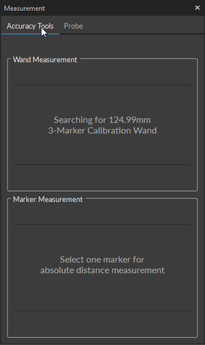
The Accuracy Tool is used to check calibration quality and tracking accuracy of a given volume. There are two tools in this tab: the Volume Accuracy tool and the Marker Measurement tool. The Accuracy tools are available under the Accuracy Tools tab in the Measurements pane.
Wand Measurement Tool
This tool works only with a fully calibrated capture volume and requires the calibration wand that was used during the process. It compares the length of the captured calibration wand to its known theoretical length and computes the percent error of the tracking volume. You can analyze the tracking accuracy from this.
Steps
In Live mode, open the Measurements pane under the Tools tab.
Access the Accuracy tools tab.
Under the Wand Measurement section, it will indicate the wand that was used for the volume calibration and its expected length (theoretical value). The wand length is specified under the Calibration pane where you can set the theoretical length to the desired value.
Bring the calibration wand into the volume.
Once the wand is in the volume, detected wand length (observed value) and the calculated wand error will be displayed accordingly.
Marker Measurement Tool
This tool calculates measured displacement of a selected marker. You can use this tool to compare the calculated displacement in Motive against how much the marker has actually moved to check the tracking accuracy of the system.
Steps
Place a marker inside the capture volume.
Select the marker in Motive.
Under the Marker Measurement section, press Reset Measurement. This zeroes the position of the marker.
Slowly translate the marker, and the absolute displacement will be displayed.
Probe

The Probe tab is used with the Measurement Probe Tool Kit. See Measurement Probe Kit Guide for specific instructions.
Probe Calibration
Calibration Frames
Number of frames to sample when calibrating the measurement probe.
Start Calibration
Initiates the probe calibration process.
Sampling Settings
Sample Frames
A total number of frames to collect for calculating the 3D location of the probe tip in respect to the markers on the probe.
Take Sample
Samples 3D location of the probe tip.
Clear All
Clears all collected probe samples.
Set Origin
Re-positions the global coordinate origin to where the probe tip is located
Set Orientation
Re-orients the global coordinate system to three of the sampled points.
Additional Settings
Sound
Enable/disable the beeping sound each time a sample is collected.
Real-Time Probe Measurement
This section of the pane displays tracking information of the probe. It displays both the real-time tracking and recorded samples. If multiple samples are collected, the distance and angle between the sampled points will be calculated and displayed.
Last updated
Was this helpful?

