LogoLogo
WebsiteSupportDownloadsForumsQuick LinksContact Us
v2.3
v2.3
  • OptiTrack Support Documentation
  • WHAT'S NEW
    • Unreal Engine: OptiTrack InCamera VFX
  • QUICK START GUIDES
    • Quick Start Guide: Getting Started
    • Quick Start Guide: Precision Capture
    • Quick Start Guide: Tutorial Videos
    • Quick Start Guide: Prime Color Setup
    • Quick Start Guide: Active Marker Tracking
    • Quick Start Guide: Outdoor Tracking Setup
  • HARDWARE
    • Cameras
      • Ethernet Cameras
        • PrimeX 41
        • PrimeX 22
        • PrimeX 13
        • PrimeX 13W
        • SlimX 13
        • Prime Color
      • USB Cameras
        • Slim 3U
        • Flex 13
        • Flex 3
        • V120:Duo
        • V120:Trio
        • V120:Duo and Trio Setup
        • Adjusting Global Origin for Tracking Bars
    • Prepare Setup Area
    • Camera Mount Structures
    • Camera Placement
    • Camera Network Setup
    • Aiming and Focusing
    • Camera Status Indicators
  • MOTIVE
    • Installation and Activation
    • Motive Basics
    • Calibration
      • Continuous Calibration
      • Calibration Squares
    • Markers
    • Assets
      • Gizmo Tool: Translate, Rotate, and Scale
    • Rigid Body Tracking
      • Aligning Rigid Body Pivot Point with a Replicated 3D Model
    • Skeleton Tracking
    • Data Recording
      • Data Types
    • Labeling
    • Data Editing
    • Data Export
      • Data Export: BVH
      • Data Export: C3D
      • Data Export: CSV
      • Data Export: FBX
      • Data Export: TRC
    • Data Streaming
    • Camera Video Types
    • Audio Recording
    • Motive HotKeys
    • Measurement Probe Kit Guide
    • Motive Batch Processor
    • Reconstruction and 2D Mode
    • Tracking Bar Coordinate System
      • Transforming Coordinate System: Global to Local
  • MOTIVE UI PANES
    • Application Settings
      • Settings: Live Reconstruction
      • Settings: General
      • Settings: Views
      • Settings: Assets
        • Skeletons
        • Rigid Body
      • Settings: Camera
    • Mouse and Keyboard
    • Assets Pane
    • Builder Pane
    • Calibration Pane
    • Control Deck
    • Data Pane
    • Data Streaming Pane
    • Devices Pane
    • Edit Tools Pane
    • Graph View Pane
    • Info Pane
    • Labels Pane
    • Log Pane
    • Marker Sets Pane
      • Marker Name XML Files
    • Measurement Pane
    • Probe Pane
    • Properties Pane
      • Properties Pane: Camera
      • Properties Pane: Force Plates
      • Properties Pane: NI-DAQ
      • Properties Pane: OptiHub2
      • Properties Pane: Rigid Body
      • Properties Pane: Skeleton
      • Properties Pane: Take
      • Properties Pane: eSync2
    • Reference View pane
    • Status Panel
    • Toolbar/Command Bar
    • Viewport
  • PLUGINS
    • OptiTrack Unreal Engine Plugin
      • Unreal Engine: OptiTrack Live Link Plugin
      • Unreal Engine: OptiTrack Streaming Client Plugin
      • Unreal Engine: HMD Setup
      • Unreal Engine: MotionBuilder Workflow
      • Unreal Engine VCS Inputs
    • OptiTrack Unity Plugin
      • Unity: HMD Setup
    • OptiTrack OpenVR Driver
    • Autodesk Maya
      • Autodesk Maya: OptiTrack Insight VCS Plugin
    • Autodesk MotionBuilder
      • Autodesk MotionBuilder Plugin
      • Autodesk MotionBuilder: OptiTrack Skeleton Plugin
      • Autodesk MotionBuilder: OptiTrack Optical Plugin
      • Autodesk MotionBuilder: OptiTrack Insight VCS Plugin
      • Autodesk MotionBuilder: Timecode Data
    • OptiTrack Peripheral API
    • External Plugins
      • Houdini 19 Integration
  • ACTIVE COMPONENTS
    • Active Components Hardware
      • Active Puck
      • CinePuck
      • BaseStation
      • Information for Assembling the Active Tags
      • Manus Glove Setup
    • Configuration
      • Active Batch Programmer
      • Active Hardware Configuration: PuTTY
      • Active Component Firmware Compatibility
    • Active Marker Tracking
      • Active Finger Marker Set
      • Active Marker Tracking: IMU Setup
  • SYNCHRONIZATION
    • Synchronization Hardware
      • External Device Sync Guide: eSync 2
      • External Device Sync Guide: OptiHub2
    • Synchronization Setup
    • OptiTrack Timecode
  • VIRTUAL PRODUCTION
    • Unreal Engine: OptiTrack InCamera VFX
    • Entertainment Marker Sets
    • PrimeX 41
  • MOVEMENT SCIENCES
    • Movement Sciences Hardware
      • General Motive Force Plate Setup
      • AMTI Force Plate Setup
      • Bertec Force Plate Setup
      • Kistler Force Plate Setup
      • Delsys EMG Setup
      • NI-DAQ Setup
      • Multiple Device Setup
      • Prime Color Setup
    • Movement Sciences Marker Sets
      • Biomechanics Marker Sets
      • Biomech (57)
      • Rizzoli Marker Sets
    • For Visual3D Users
  • VIRTUAL REALITY
    • VR Plugins
      • VR Unreal Engine
        • OptiTrack Unreal Engine Plugin
        • Unreal Engine: OptiTrack Live Link Plugin
        • Unreal Engine: OptiTrack Streaming Client Plugin
        • Unreal Engine VCS Inputs
      • VR Unity
        • OptiTrack Unity Plugin
      • VR OpenVR
        • OptiTrack OpenVR Driver
    • VR HMD Setup
      • Unreal Engine: HMD Setup
      • Unity: HMD Setup
      • Manually Calibrating the HMD Pivot Point
      • Sync Configuration with an HTC Vive System
    • Navigation Controller Guide
    • SlimX 13
    • Active Marker Tracking
      • Active Finger Marker Set
      • Active Marker Tracking: IMU Setup
    • Synchronization Hardware
      • External Device Sync Guide: eSync 2
      • External Device Sync Guide: OptiHub2
  • ANIMATION
    • Autodesk Maya
      • Autodesk Maya: OptiTrack Insight VCS Plugin
    • Autodesk MotionBuilder
      • Autodesk MotionBuilder Plugin
      • Autodesk MotionBuilder: OptiTrack Skeleton Plugin
      • Autodesk MotionBuilder: OptiTrack Optical Plugin
      • Autodesk MotionBuilder: OptiTrack Insight VCS Plugin
      • Autodesk MotionBuilder: Timecode Data
  • ROBOTICS
    • PrimeX 22
    • Outdoor Tracking Setup
  • DEVELOPER TOOLS
    • Developer Tools Overview
    • NatNet SDK
      • NatNet 4.0
      • NatNet: Class/Function Reference
      • NatNet: Creating a Managed (C sharp) Client Application
      • NatNet: Creating a Native (C++) Client Application
      • NatNet: Data Types
      • NatNet: Matlab Wrapper
      • NatNet: Migration to NatNet 3.0 libraries
      • NatNet: RebroadcastMotiveData Sample
      • NatNet: Remote Requests/Commands
      • NatNet: Sample Projects
      • NatNet: Unicast Data Subscription Commands
      • Latency Measurements
    • Motive API
      • Motive API: Quick Start Guide
      • Motive API Overview
      • Motive API: Function Reference
      • Motive API Camera Calibration
    • Camera SDK
      • Camera SDK Classes
        • Class: cCameraGroupFilterSettings
        • Class: cCameraGroupMarkerSizeSettings
        • Class: cCameraGroupPointCloudSettings
        • Class: cCameraModule
        • Class: cRigidBodySettings
        • Class: cRigidBodySolutionTest
        • Class: cTTAPIListener
        • Class: cUID
  • MARKER SETS
    • Full Body
      • Baseline (37)
      • Baseline + Hinged Toe (41)
      • Baseline + Hinged Toe, with Headband (41)
      • Baseline + 13 Additional Markers (50)
      • Biomech (57)
      • Conventional (39)
    • Full Body + Fingers
      • Baseline + Hinged Toe + Fingers (49)
      • Baseline + 11 Additional Markers + Fingers (54)
      • Manus Glove Setup
    • Upper
      • Baseline Upper (25)
      • Baseline Upper Body + Fingers (33)
      • Conventional Upper (27)
    • Lower
      • Baseline Lower (20)
      • Helen Hayes Lower (19)
      • Conventional Lower (16)
    • Hand and Fingers
      • Left and Right Hand (11)
      • Active Finger Marker Set
    • Rizzoli Marker Sets
    • Entertainment Marker Sets
    • Rigid Body Skeleton Marker Set
  • GENERAL TROUBLESHOOTING
    • Troubleshooting
    • Running Motive on High DPI Displays
    • Firewall Settings
Powered by GitBook
On this page

Was this helpful?

Export as PDF
  1. MOTIVE
  2. Tracking Bar Coordinate System

Transforming Coordinate System: Global to Local

PreviousTracking Bar Coordinate SystemNextMOTIVE UI PANES

Last updated 2 years ago

Was this helpful?

The API reports "world-space" values for markers and rigid body objects at each frame. It is often desirable to convert the coordinates of points reported by the API from the world-space (or global) coordinates into the local space of the rigid body. This is useful, for example, if you have a rigid body that defines the world space that you want to track markers within.

Rotation values are reported as both quaternions, and as roll, pitch, and yaw angles (in degrees). Quaternions are a four-dimensional rotation representation that provide greater mathematical robustness by avoiding "gimbal" points that may be encountered when using roll, pitch, and yaw (also known as Euler angles). However, quaternions are also more mathematically complex and are more difficult to visualize, which is why many still prefer to use Euler angles.

There are many potential combinations of Euler angles so it is important to understand the order in which rotations are applied, the handedness of the coordinate system, and the axis (positive or negative) that each rotation is applied about.

These are the conventions used in the API for Euler angles:

  • Rotation order: XYZ

  • All coordinates are *right-handed*

  • Pitch is degrees about the X axis

  • Yaw is degrees about the Y axis

  • Roll is degrees about the Z axis

  • Position values are in millimeters

To create a transform matrix that converts from world coordinates into the local coordinate system of your chosen rigid body, you will first want to compose the local-to-world transform matrix of the rigid body, then invert it to create a world-to-local transform matrix.

To compose the rigid body local-to-world transform matrix from values reported by the API, you can first compose a rotation matrix from the quaternion rotation value or from the yaw, pitch, and roll angles, then inject the rigid body translation values. Transform matrices can be defined as either "column-major" or "row-major". In a column-major transform matrix, the translation values appear in the right-most column of the 4x4 transform matrix. For purposes of this article, column-major transform matrices will be used. It is beyond the scope of this article, but it is just as feasible to use row-major matrices by transposing matrices.

In general, given a world transform matrix of the form: M = [ [ ] Tx ] [ [ R ] Ty ] [ [ ] Tz ] [ 0 0 0 1 ]

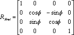
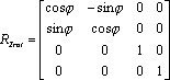
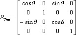
where Tx, Tz, Tz are the world-space position of the origin (of the rigid body, as reported from the API), and R is a 3x3 rotation matrix composed as: R = [ Rx (Pitch) ] * [ Ry (Yaw) ] * [ Rz (Roll) ]

where Rx, Ry, and Rz are 3x3 rotation matrices composed according to:

A handy trick to know about local-to-world transform matrices is that once the matrix is composed, it can be validated by examining each column in the matrix. The first three rows of Column 1 are the (normalized) XYZ direction vector of the world-space X axis, column 2 holds the Y axis, and column 3 is the Z axis. Column 4, as noted previously, is the location of the world-space origin. To convert a point from world coordinates (coordinates reported by the API for a 3D point anywhere in space), you need a matrix that converts from world space to local space. We have a local-to-world matrix (where the local coordinates are defined as the coordinate system of the rigid body used to compose the transform matrix), so inverting that matrix will yield a world-to-local transformation matrix. Inversion of a general 4x4 matrix can be slightly complex and may result in singularities, however we are dealing with a special transform matrix that only contains rotations and a translation. Because of that, we can take advantage of the method shown here to easily invert the matrix:

Once the world matrix is converted, multiplying it by the coordinates of a world-space point will yield a point in the local space of the rigid body. Any number of points can be multiplied by this inverted matrix to transform them from world (API) coordinates to local (rigid body) coordinates.

The API includes a sample (markers.sln/markers.cpp) that demonstrates this exact usage.

http://stackoverflow.com/questions/2624422/efficient-4x4-matrix-inverse-affine-transform