Settings: Views
Last updated
Was this helpful?
Last updated
Was this helpful?
Camera Health Info
Displays various assessments of camera health over the 2D camera views, for troubleshooting performance issues. If any performance issues is detected, corresponding problem will be listed at the bottom of the 2D camera view.
Reticles
When enabled, renders a crosshair on top of the 2D camera views, which can be useful for camera aiming.
Masks
Enables displaying masked area on the 2D camera views, in red.
Backproject Markers
Enables markers selected from the 3D Perspective View to be also highlighted with yellow crosshairs in the 2D camera view, based on calculated position. Crosshairs that are not directly over the marker tend to indicate occlusion or poor camera calibration.
Marker Filter
Marker Coordinates
Displays 2D coordinate of the detected object centroids within the captured image, in pixels.
Marker Centroids
Displays crosshairs on marker centroids in the 2D view.
Marker Boundaries
Displays a box around each marker, indicating its calculated edges after the brightness threshold.
Marker Circularity
Displays the roundness of an object. A value of 1 indicates maximum roundness, while a value of 0 indicates no roundness.Pixel inspector enabled in 2D view
Marker Aspect Ratio
Displays the ratio of object width to object height as a decimal, resolved to .01 pixel.
Marker Size
Displays the area of the object in pixels, accurate to .01 pixel.
Marker Label
Displays the pre-identified labels assigned to 2D objects for initial tracking from frame to frame.
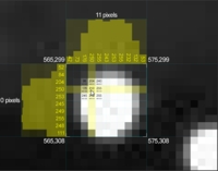
Pixel Inspection
Displays X,Y coordinates for cursor location when hovering over a camera, and pixel brightness for selected pixels when a region is drag-selected. Inspecting pixel brightness can be useful during camera focusing, tuning, and aiming.
Texture Streaming
Disables or enables texture streaming of reference videos on the 2D camera viewport.
Visual FPS Target
Sets a maximum frame display rate for the 2D camera view.
Background Color
Selects the color to display in the viewport between camera panes.
Camera Info
Enables text overlay of pertinent camera information on the 2D Multi Camera view panes. Displayed information includes image mode, time, data rate, frame ID, visual FPS, number of objects, camera serial, exposure value, threshold value, IR intensity value, internal temperature, and camera sync mode.
Show Distortion
Displays each camera’s lens distortion map.
Overlay Color
Selects the color of the lens distortion map display.
Overlay Transparency
Selects the transparency percentage for the lens distortion map.
Overlay Resolution
Selects the level of details for displaying the lens distortion. More specifically, it sets number of distortion grids on the width and height of the distortion map.
Show as Predistortion
Selects whether the map is shown as pre-distorted or distorted.
Display Mode
Sets levels of details for the markers displayed in the multi-camera 2D view. Available modes are Frame Buffer, Marker Centers, and Automatic LOD modes. Default is Automatic LOD.
Automatic LOD switches between Frame Buffer mode and Marker Centers mode depending on the zooming of the 2D camera view, or the LOD threshold setting.
Frame Buffer mode pushes the entire camera frame to the video card for scaling and display. It provides verbose information on detected reflections and centroids, but it is data intensive at the same time.
Marker centers mode merely defines a white circle of the rough size and shape of the marker as it would appear. More specifically, it displays the reflections by its size and location and is significantly less hardware intensive.
Pane Gap
The distance between 2D Multi View camera panes, in pixels.
LOD Threshold
The size, zoom percentage, at which the system switches between Marker Centers and Frame Buffer mode.
Raster Priority
Defines the update rate for the camera pixel data shown in the 2D camera views. The priority value ranges from 1 - 6, and a higher priority indicates a higher rate of update.
Camera Names
Displays the camera model, serial, and master/slave status above and below camera objects.
Text Size
Adjusts the size of the camera name text.
Solid Cameras
Setting this to true disables camera object transparency in the 3D Perspective View.
Labeled Marker Color
Active Marker Color
Unlabeled Marker Color
Selection Color
Sets the color of selections in the 3D view port.
Marker History
Displays a history trail of marker positions over time.
Selected History Only
Determines whether marker history will be shown for selected markers or all markers.
Assigned Markers
Show Marker Count
Displays the number of markers detected by the system as well as the number of markers selected at the bottom right corner of the perspective view.
Show Marker Labels
Displays marker labels for selected markers in the perspective view.
Show Timecode
Enables or disables timecode values displayed on the 3D viewport. Timecode will be available only when the timecode signal is inputted through the eSync.
Show Marker Infos
When this is set to true. 3D positions and estimated diameter of selected markers will be displayed on the 3D viewport.
Display mode
Toggles camera numbers on and off in the 3D Perspective View.
Marker Diameter
Determines whether marker sizes in the 3D Perspective View are represented by the calculated size or overwritten with a set diameter.
Diameter (mm)
Sets the diameter in millimeters for marker sizes in the 3D Perspective View, if Marker Diameter is set to Set Diameter.
Background Color
Selects the background color displayed in the 3D Perspective View.
Fog Effect
Turns a gradient “fog” effect on in the 3D Perspective View.
OptiTrack Logo
Overlays the OptiTrack logo over top of the 3D Perspective View.
Grid Color
Selects the color of the ground plane grid in the 3D Perspective View.
Grid Transparency
Selects the level of transparency applied to the ground plane grid in the 3D Perspective View.
Grid Size
Selects the size of the ground plane grid in the 3D Perspective View. Specifically, it sets the number of grids (20cm x 20cm) along the positive and negative direction in both the X and Z axis.
Coordinate Axis
Displays the coordinate axis in the 3D view port.
Video Overlay Display FPS
Controls of often scene video overlays are updated for display.
Undistort Video Overlay
Removes distortions from the grid when displaying the video distortion overlay in the reference video.
Show Tracked Rays
Show Untracked Rays
Displays the untracked rays in the view port. Untracked rays are the rays which start from each camera and goes through the detected 2D centroids, but fails to be reconstructed in the 3D space. When there are several untracked rays in the capture, it is usually a sign of bad calibration or extreme reconstruction settings.
Show Missing Rays
Displays the missing rays in the view port. Missing rays form when tracking a rigid body or a skeleton, and it indicates expected marker rays that are not detected from the camera view but expected from the rigid body or the skeleton solve.
Show Two Marker Distance
Enabling this will display distance between two markers in the Perspective View pane. Two markers must be selected to calculate the distance.
Show Three Marker Angle
Enabling this will measure an angle formed by three markers in the Perspective View pane. Three markers must be selected, and the calculated angle will follow the selection order. When all three markers are selected at once, the widest angle will be measured.
Show Marker Colors
When labeled, each skeleton marker is colored as defined in the corresponding markerset template. Enabling this setting will color the markers for better identification of the marker labels.
Show Marker Sticks
Show Selected Residual
Displays the offset distance between rays converging into a marker. The residual value will be displayed on top of the view pane. Note that ray information will be displayed only in the 2D data.
Tracked Ray Color
Sets the color for Tracked Rays in the 3D Perspective View.
Untracked Ray Color
Sets the color for untracked Rays in the 3D Perspective View.
Missing Ray Color
Sets the color for Missing Rays in the 3D Perspective View.
Tracked Ray Transparency
Sets the level of transparency for Tracked Rays.
Untracked Ray Transparency
Sets the level of transparency for Untracked Rays.
Missing Ray Transparency
Sets the level of transparency for Missing Rays.
Missing Ray Threshold
Sets the distance in millimeters that a 2D marker must be from an expected location before declaring the marker missing.
Color Scheme
Toggles the theme for the timeline playback graph between light and dark.
Background Color
Specifies the background color for the timeline playback graph.
Autoscale
Automatically scales trajectory graphs in the Timeline pane.
Preferred Live Layout
Preferred Edit Layout
Scope Duration
Show Markers
Overlays markers in the reference video when this setting is set to true.
Show Skeletons
Overlays skeletons in the reference video when this setting is set to true.
Show Rigid Bodies
Overlays rigid bodies in the reference video when this setting is set to true.
Show Distortion Grid
Displays reference camera distortion grid in the reference view.
Lock Aspect Ratio
Keeps the aspect ratio constant for reference videos.
Split Horizontal
When set to true, multiple reference view is divided into multiple columns in the reference view pane.
Maximum Exposure Display
Panel Output
Default: Standard. Decides whether the calibration process is displayed in a list format or a grid format. Grid format allows more camera progresses to be seen in the pane.
Status Ring
Solver Visualizations
Default: Show. This toggles the display of wand samples and point cloud calibration visuals in the 2D and 3D view. If you're running on a lower end machine or graphics card with a large system, it is best to turn this feature off. The visual display will in fact eat up some computing power you may want reserved for getting quicker calibration results.
Lens Distortion
Default: Show. Use this to toggle the display of the lens distortion solution results in the 2D view. The lens distortion will be represented by a square grid that maps the distortion.
Cameras
Default: Show. This toggles the display of the cameras during the solve.
Wanding Projection
Default: Show. This toggles the display of wand samples projected in the 3D view. Turn this off if you're calibrating a very large system.
Projection Error
Default: Show. This toggles the display of error, reported as a color in the projected wand samples and markers. The wand samples will have a color between blue (good sample) and red (poor sample). Make sure the samples you collect are mostly good samples. As will all visual feedback, it may be a good idea to turn this off if you're calibrating a larger system.
Residual Error
Default: 6 mm. Set the tolerance for the reported error in the projected marker sample during calibration.
Wand Error
Default: 8 mm. This sets the tolerance for the reported error in the projected wand sample.
Sample Spacing
Default: 1. Use this to increase the spacing between displayed samples that are projected in the 3D view. Increasing this will skip more samples but will make the visual wand projections easier to see.
When enabled, filtered reflections will be labeled with the corresponding in the 2D camera view.
Sets the color for in the 3D view port.
Sets the color for in the 3D viewport.
Sets the color for in the 3D view port.
Enables or disables display of (also called solved, expected marker positions) on rigid body or skeleton assets
Displays tracked rays in the view port. Tracked rays are marker rays with residual values less than the Maximum Residual setting from the . In other words, tracked rays are marker rays that are contributing to 3D reconstructions.
Setting this to true will show on skeleton assets for clearer identification of skeleton markers and segments in each individual actor. Setting this to true will reveal marker sticks in 3D data.
Preferred Layout to be used for the Live mode .
Preferred Layout to be used for the Edit mode .
This setting sets the time scope of the plotted in Live mode. By default, this is set to 1000, which means 1000 captured frames of past tracking history will be plotted in Live mode. You can increase this to plot more history data or decrease it to zoom into the tracking history.
Controls the maximum value of the exposure slider in .
This section covers through the display options for the calibration features. In previous releases, these options existed in the .
Default: Visualize. Enables the to glow during calibration in order to display the wanding process.