LogoLogo
WebsiteSupportDownloadsForumsQuick LinksContact Us
v2.3
v2.3
  • OptiTrack Support Documentation
  • WHAT'S NEW
    • Unreal Engine: OptiTrack InCamera VFX
  • QUICK START GUIDES
    • Quick Start Guide: Getting Started
    • Quick Start Guide: Precision Capture
    • Quick Start Guide: Tutorial Videos
    • Quick Start Guide: Prime Color Setup
    • Quick Start Guide: Active Marker Tracking
    • Quick Start Guide: Outdoor Tracking Setup
  • HARDWARE
    • Cameras
      • Ethernet Cameras
        • PrimeX 41
        • PrimeX 22
        • PrimeX 13
        • PrimeX 13W
        • SlimX 13
        • Prime Color
      • USB Cameras
        • Slim 3U
        • Flex 13
        • Flex 3
        • V120:Duo
        • V120:Trio
        • V120:Duo and Trio Setup
        • Adjusting Global Origin for Tracking Bars
    • Prepare Setup Area
    • Camera Mount Structures
    • Camera Placement
    • Camera Network Setup
    • Aiming and Focusing
    • Camera Status Indicators
  • MOTIVE
    • Installation and Activation
    • Motive Basics
    • Calibration
      • Continuous Calibration
      • Calibration Squares
    • Markers
    • Assets
      • Gizmo Tool: Translate, Rotate, and Scale
    • Rigid Body Tracking
      • Aligning Rigid Body Pivot Point with a Replicated 3D Model
    • Skeleton Tracking
    • Data Recording
      • Data Types
    • Labeling
    • Data Editing
    • Data Export
      • Data Export: BVH
      • Data Export: C3D
      • Data Export: CSV
      • Data Export: FBX
      • Data Export: TRC
    • Data Streaming
    • Camera Video Types
    • Audio Recording
    • Motive HotKeys
    • Measurement Probe Kit Guide
    • Motive Batch Processor
    • Reconstruction and 2D Mode
    • Tracking Bar Coordinate System
      • Transforming Coordinate System: Global to Local
  • MOTIVE UI PANES
    • Application Settings
      • Settings: Live Reconstruction
      • Settings: General
      • Settings: Views
      • Settings: Assets
        • Skeletons
        • Rigid Body
      • Settings: Camera
    • Mouse and Keyboard
    • Assets Pane
    • Builder Pane
    • Calibration Pane
    • Control Deck
    • Data Pane
    • Data Streaming Pane
    • Devices Pane
    • Edit Tools Pane
    • Graph View Pane
    • Info Pane
    • Labels Pane
    • Log Pane
    • Marker Sets Pane
      • Marker Name XML Files
    • Measurement Pane
    • Probe Pane
    • Properties Pane
      • Properties Pane: Camera
      • Properties Pane: Force Plates
      • Properties Pane: NI-DAQ
      • Properties Pane: OptiHub2
      • Properties Pane: Rigid Body
      • Properties Pane: Skeleton
      • Properties Pane: Take
      • Properties Pane: eSync2
    • Reference View pane
    • Status Panel
    • Toolbar/Command Bar
    • Viewport
  • PLUGINS
    • OptiTrack Unreal Engine Plugin
      • Unreal Engine: OptiTrack Live Link Plugin
      • Unreal Engine: OptiTrack Streaming Client Plugin
      • Unreal Engine: HMD Setup
      • Unreal Engine: MotionBuilder Workflow
      • Unreal Engine VCS Inputs
    • OptiTrack Unity Plugin
      • Unity: HMD Setup
    • OptiTrack OpenVR Driver
    • Autodesk Maya
      • Autodesk Maya: OptiTrack Insight VCS Plugin
    • Autodesk MotionBuilder
      • Autodesk MotionBuilder Plugin
      • Autodesk MotionBuilder: OptiTrack Skeleton Plugin
      • Autodesk MotionBuilder: OptiTrack Optical Plugin
      • Autodesk MotionBuilder: OptiTrack Insight VCS Plugin
      • Autodesk MotionBuilder: Timecode Data
    • OptiTrack Peripheral API
    • External Plugins
      • Houdini 19 Integration
  • ACTIVE COMPONENTS
    • Active Components Hardware
      • Active Puck
      • CinePuck
      • BaseStation
      • Information for Assembling the Active Tags
      • Manus Glove Setup
    • Configuration
      • Active Batch Programmer
      • Active Hardware Configuration: PuTTY
      • Active Component Firmware Compatibility
    • Active Marker Tracking
      • Active Finger Marker Set
      • Active Marker Tracking: IMU Setup
  • SYNCHRONIZATION
    • Synchronization Hardware
      • External Device Sync Guide: eSync 2
      • External Device Sync Guide: OptiHub2
    • Synchronization Setup
    • OptiTrack Timecode
  • VIRTUAL PRODUCTION
    • Unreal Engine: OptiTrack InCamera VFX
    • Entertainment Marker Sets
    • PrimeX 41
  • MOVEMENT SCIENCES
    • Movement Sciences Hardware
      • General Motive Force Plate Setup
      • AMTI Force Plate Setup
      • Bertec Force Plate Setup
      • Kistler Force Plate Setup
      • Delsys EMG Setup
      • NI-DAQ Setup
      • Multiple Device Setup
      • Prime Color Setup
    • Movement Sciences Marker Sets
      • Biomechanics Marker Sets
      • Biomech (57)
      • Rizzoli Marker Sets
    • For Visual3D Users
  • VIRTUAL REALITY
    • VR Plugins
      • VR Unreal Engine
        • OptiTrack Unreal Engine Plugin
        • Unreal Engine: OptiTrack Live Link Plugin
        • Unreal Engine: OptiTrack Streaming Client Plugin
        • Unreal Engine VCS Inputs
      • VR Unity
        • OptiTrack Unity Plugin
      • VR OpenVR
        • OptiTrack OpenVR Driver
    • VR HMD Setup
      • Unreal Engine: HMD Setup
      • Unity: HMD Setup
      • Manually Calibrating the HMD Pivot Point
      • Sync Configuration with an HTC Vive System
    • Navigation Controller Guide
    • SlimX 13
    • Active Marker Tracking
      • Active Finger Marker Set
      • Active Marker Tracking: IMU Setup
    • Synchronization Hardware
      • External Device Sync Guide: eSync 2
      • External Device Sync Guide: OptiHub2
  • ANIMATION
    • Autodesk Maya
      • Autodesk Maya: OptiTrack Insight VCS Plugin
    • Autodesk MotionBuilder
      • Autodesk MotionBuilder Plugin
      • Autodesk MotionBuilder: OptiTrack Skeleton Plugin
      • Autodesk MotionBuilder: OptiTrack Optical Plugin
      • Autodesk MotionBuilder: OptiTrack Insight VCS Plugin
      • Autodesk MotionBuilder: Timecode Data
  • ROBOTICS
    • PrimeX 22
    • Outdoor Tracking Setup
  • DEVELOPER TOOLS
    • Developer Tools Overview
    • NatNet SDK
      • NatNet 4.0
      • NatNet: Class/Function Reference
      • NatNet: Creating a Managed (C sharp) Client Application
      • NatNet: Creating a Native (C++) Client Application
      • NatNet: Data Types
      • NatNet: Matlab Wrapper
      • NatNet: Migration to NatNet 3.0 libraries
      • NatNet: RebroadcastMotiveData Sample
      • NatNet: Remote Requests/Commands
      • NatNet: Sample Projects
      • NatNet: Unicast Data Subscription Commands
      • Latency Measurements
    • Motive API
      • Motive API: Quick Start Guide
      • Motive API Overview
      • Motive API: Function Reference
      • Motive API Camera Calibration
    • Camera SDK
      • Camera SDK Classes
        • Class: cCameraGroupFilterSettings
        • Class: cCameraGroupMarkerSizeSettings
        • Class: cCameraGroupPointCloudSettings
        • Class: cCameraModule
        • Class: cRigidBodySettings
        • Class: cRigidBodySolutionTest
        • Class: cTTAPIListener
        • Class: cUID
  • MARKER SETS
    • Full Body
      • Baseline (37)
      • Baseline + Hinged Toe (41)
      • Baseline + Hinged Toe, with Headband (41)
      • Baseline + 13 Additional Markers (50)
      • Biomech (57)
      • Conventional (39)
    • Full Body + Fingers
      • Baseline + Hinged Toe + Fingers (49)
      • Baseline + 11 Additional Markers + Fingers (54)
      • Manus Glove Setup
    • Upper
      • Baseline Upper (25)
      • Baseline Upper Body + Fingers (33)
      • Conventional Upper (27)
    • Lower
      • Baseline Lower (20)
      • Helen Hayes Lower (19)
      • Conventional Lower (16)
    • Hand and Fingers
      • Left and Right Hand (11)
      • Active Finger Marker Set
    • Rizzoli Marker Sets
    • Entertainment Marker Sets
    • Rigid Body Skeleton Marker Set
  • GENERAL TROUBLESHOOTING
    • Troubleshooting
    • Running Motive on High DPI Displays
    • Firewall Settings
Powered by GitBook
On this page
  • Steps
  • 1. Export a Marker XML
  • 2. Customize the XML
  • 3. Import Skeleton XML
  • Notes for added Markers

Was this helpful?

Export as PDF
  1. MOTIVE UI PANES
  2. Marker Sets Pane

Marker Name XML Files

PreviousMarker Sets PaneNextMeasurement Pane

Last updated 2 years ago

Was this helpful?

This page includes detailed step-by-step instructions on customizing the marker name XML files for skeletons and Marker Set assets.

In order to customize the skeleton marker labels, marker colors, and marker sticks, a Marker XML file needs be exported, customized, and loaded back in. For skeletons, modified Marker XML files can only be used with the same Marker Set template. In other words, if you exported a Baseline (41) skeleton and modified the labeling XML file, same Baseline (41) Marker Set needs to be created in order to import the customized XML file. The following section describes the steps for customizing skeleton XML templates.

Steps

1. Export a Marker XML

a) First, choose a Marker Set from the , and a skeleton.

b) Right-click on a skeleton asset in the , and select Export Markers.

c) In the export dialog window, select a directory to save the Marker Name Template (.xml) file. Click Save to export.

Export Markers option shown in the Assets pane.

2. Customize the XML

Customize Marker Labels

a) Open the exported XML file using a text editor. It will contain corresponding marker label information under the MarkerNameMap section.

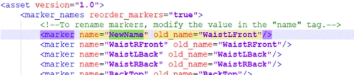
b) Customize the marker labels from the XML file. Under the MakerNames section of the XML, modify labels for the name variables with the desired name, but do not change labels for oldName variables. The order of the markers should remain the same.

c) If you changed marker labels, the corresponding marker names must also be renamed within the Marker and Marker Sticks definitions as well. Otherwise, the marker colors and marker sticks will not be defined properly.

Customize Marker Sticks and Colors

b) Here, you can customize the marker colors and the marker sticks. For each marker name, you must use exactly same marker labels that were defined by the MarkerNames section of the same XML file. If any marker label was changed in the MarkerNames section, the changed name must be reflected in the respective colors and sticks definitions as well. In other words, if a Custom_Name was assigned under name for a label in the MarkerNameMap section <Marker name="Custom_Name" oldName="Original_Name" />, the same Custom_Name must be used to rename all the respective marker names within Marker and MarkerSticks elements of the XML.

  • Marker Colors: For each marker in a skeleton, there will be a respective name and color definitions under the Markerssection of the XML. To change corresponding marker colors for the template, edit the RGB parameter and save the XML file.

  • Marker Sticks: A marker stick is simply a line interconnecting two labeled markers within the skeleton. Each marker stick definition consists of two marker labels for creating a marker stick and a RGB value for its color. To modify the marker sticks, edit the marker names and the color values. You can also define additional marker sticks by copying the format from the other marker stick definitions.

3. Import Skeleton XML

Creating new skeletons

Renaming Markers on existing Skeleton

You can also apply customized XML into an existing skeleton using the renaming feature. Right-click on a skeleton asset in the Project pane and select the Rename Markers from the context menu, and this will bring up a dialog window for importing a skeleton XML template. Import the customized XML template and modified labels will be applied to the asset. This feature must also be used if extra markers were added to the default XML template.

Notes for added Markers

Applying Customized XML with Added Markers

  1. [Motive: Builder pane] Create the skeleton using the markers without including the extra markers that were added. These markers will be added on the next step.

  2. [Motive:Assets pane] Select the skeleton and click Rename Markers to import the customized skeleton XML template.

Modifying marker labels. Default HeadTop marker label is changed to NewHeadTop for skeletons using the XML template file.

a) To customize the Marker Colors and Sticks, open the exported XML file using a text editor and scroll down to the Markers and Marker Sticks section. If the Markers and Marker Sticks section does not exist in the exported XML file, you could be using an old skeleton created before Motive 1.10. and exporting old skeleton will provide these sections in the XML.

MarkerColors definition section in the skeleton template XML file.
MarkerSticks definition section in the skeleton template XML file.

Now that you have customized the XML file, it can be loaded each time when creating new skeletons. In the under skeleton creation options, select the corresponding Marker Set. Then, under the Marker Names drop down menu, choose (…) to browse to import the XML file. When you the skeleton, the custom marker labels, marker sticks, and marker labels will be applied. You will need to auto-label the take again if you are working on a recorded TAK file.

If you manually to a skeleton, you must rename the skeleton after creating it. See more at the section.

Loading skeleton XML when creating a new skeleton
Customized skeleton markers labels.

In order to replace the existing labels with the modified labels, you will need to first delete the existing markers labels and the skeleton asset again with the renamed markers, or you can Reconstruct and Auto-label the entire Take again.

Renaming existing skeleton by importing a XML template file.

XML definitions can also be applied to on a skeleton asset. When extra markers were added to a skeleton, its exported XML file will have the corresponding marker labels logged at the end of the MarkerNames section, and the labels for these markers can be customized from the exported XML file. The marker color and sticks definitions for extra markers will not be created automatically. To assign the marker colors and sticks for the extra markers, you will need to type additional instances which exactly copies the format that is used in other instances.

A newly created skeleton will not contain the added markers within the asset. To apply the customized XML for the extra markers, you must first create a skeleton of the same markerset and add the extra markers before importing the XML. When adding multiple markers, it is important that they are added in exactly the same order that it was added on the skeleton which was exported; Otherwise, the extra labels will be assigned incorrectly. After adding the corresponding markers, use the feature to apply the customized XML file. Lastly, auto-labeled the Take to assign the corresponding marker definitions onto the skeleton.

[Motive: Perspective View pane] Add the extra markers onto the selected skeleton asset. See how to .

[Motive:Assets pane] When working with a recorded Take, first delete the existing marker labels using the Delete Marker Labels from the , and auto-label the Take to label the markers using the imported XML file.

Updating
auto-label
added markers
Rename Markers
add markers
Assets pane
Builder pane
Assets pane
Builder pane
Added Markers
added extra markers
Create
create