Settings: Live Pipeline
In Motive, the Application Settings can be accessed under the View tab or by clicking ![]() icon on the main toolbar. Default Application Settings can be recovered by Reset Application Settings under the Edit Tools tab from the main Toolbar.
icon on the main toolbar. Default Application Settings can be recovered by Reset Application Settings under the Edit Tools tab from the main Toolbar.
Overview
Live-Pipeline settings contain camera filter settings and solver settings for obtaining 3D data in Motive. Please note that these settings are optimized by default and should provide high-quality tracking for most applications. The settings that might need to be adjusted based on the application are visible by default (i.e. not advanced).
The most commonly changed settings are...
Coarse/Fine IK Iterations - This helps Skeletons converge to a good pose quickly when Skeletons start in a difficult to track pose.
Minimum Rays to Start/Continue - This helps reduce false markers from semi-reflective objects when there is a lot of camera overlap. It also allows you to not track when seen by only one camera (Minimum Rays to Continue = 2).
Boot Skeleton Label Percentage - A lower value will allow Skeletons to boot more quickly when entering the volume. A higher value will prevent untracked Skeletons from attempting to track using other markers in the volume.
Solver Basic Settings
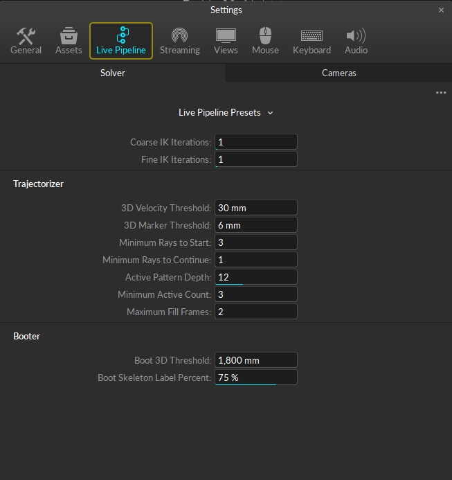
The solver settings control how each marker trajectory gets reconstructed into the 3D space and how Rigid Bodies and Skeletons track. The solver is designed to work for most applications without needing to modify any settings. However, in some instances changing some settings will lead to better tracking results. The settings that may need to be changed are visible by default. There are also a large number of advanced settings that we don’t recommend changing, but the tooltips are available if needed. The settings that users may need to change are listed below with descriptions.
General Settings
These are general tracking settings for the solver not related to creating 3D markers or booting assets. Do not change these settings in Live mode as incorrect settings can negatively affect the tracking, this is mostly useful when optimizing 3D data for recorded captures with actors in difficult positions to track.
Coarse IK Iterations
What it does: This property sets the number of Coarse IK iterations, which are fast but not accurate inverse kinematic solve to place the Skeleton on the associated markers.
When to change: Do not change this property in Live mode. In recorded captures, this property may need to be changed, under the TAK properties, if the recording(s) starts with actors who are not in standing-up positions. Sometimes in these recordings, the Skeletons may not solve on the first couple frames, and in these cases, increasing this setting will allow the Skeleton to converge on the first frame.
Fine IK Iterations
What it does: This property sets the number of Fine IK iterations, which are slow but accurate inverse kinematic solve to place the final pose of the Skeleton on the associated markers. Increasing this setting may result in higher CPU usage.
When to change: Do not change this property in Live mode. In recorded captures, this property may need to be changed, under the TAK properties, if the recording(s) starts with actors who are not in standing-up positions or the ones that are difficult to solve. Sometimes in these recordings, the Skeletons may not solve on the first couple frames, and in these cases, increasing this setting will allow the Skeleton to converge on the first frame.
Trajectorizer
The Trajectorizer settings control how the 2D marker data is converted into 3D points in the calibrated volume. The trajectorizer performs reconstruction of 2D data into 3D data, and these settings control how markers are created in the 3D scene over time.
3D Velocity Threshold
What it does: This setting controls the maximum distance between a marker trajectory and its predicted position.
When to change: This setting may need to be increased when tracking extra fast assets. The default setting should track most applications. Attempt to track with default settings first, and if there are any gaps in the marker trajectories, you can incrementally increase the distance until stable tracking is achieved.
3D Marker Threshold
What it does: This setting controls the maximum distance between a ray and the marker origin.
Minimum Rays to Start
What it does: This sets the minimum number of tracked rays that need to converge on one location to create a new marker in 3D. This is also the minimum number of calibrated cameras that see the same target marker within the 3D threshold value for them to initially get trajectorized into a 3D point.
When to change: For large volumes with high camera counts, increasing this value may provide more accurate and robust tracking. The default value of 3 works well with most medium and small-sized volumes. For volumes that only have two cameras, the trajectorizer will use a value of 2 even when it's not explicitly set.
Minimum Rays to Continue
What it does: This sets the minimum number of rays that need to converge on one location in order to continue tracking a marker that already initialized near that location. A value of 1 will use asset definitions to continue tracking markers even when a 3D marker could not have been created from the camera data without the additional asset information.
When to change: This is set to 1 by default. It means that Motive will continue the 3D data trajectory as long as at least one ray is obtained and the asset definition matches. When single ray tracking is not desired or for volumes with a large number of cameras, change this value to 2 to utilize camera overlaps in the volume.
Active Pattern Depth
What it does: This setting is used for tracking active markers only, and it sets the number of frames of motion capture data used to uniquely identify the ID value of an active marker.
When to change: When using a large number of active tags or active pucks, this setting may need to be increased. It's recommended to use the active batch programmer when configuring multiple active components, and when each batch of active devices has been programmed, the programmer will provide a minimum active pattern depth value that should be used in Motive.
Minimum Active Count
What it does: The total number of rays that must contribute to an active marker before it is considered active and given an ID value.
When to change: Change this setting to increase the confidence in the accuracy of active marker ID values (not changed very often).
Maximum Fill Frames
What it does: The number of frames of data that the solver will attempt to fill if a marker goes missing for some reason. This value must be at least 1 if you are using active markers.
When to change: If you would like more or fewer frames to be filled when there are small gaps.
Booter
The Booter settings control when the assets start tracking, or boot, on the trajectorized 3D markers in the scene. In other words, these settings determine when Rigid Bodies and/or Skeletons track on a set of markers.
Boot 3D Threshold
What it does: This controls the maximum distance between a pair of Marker Constraints to be considered as an edge in the label graph.
When to change: The default settings should work for most applications. This value may need to be increased to track large assets with markers that are far apart.
Boot Skeleton Label Percent
What it does: This sets the percentage of Skeleton markers that need to be trajectorized in order to track the corresponding Skeleton(s). If needed, this setting can also be configured per each asset from the corresponding asset properties using the Properties pane.
When to change: The default settings should work for most applications. Set this value to about 75% to help keep Skeletons from booting on other markers in the volume if there are similar Skeleton definitions or lots of loose markers in the scene. If you would like Skeletons to boot faster when entering the volume, then you can set this value lower.
Solver Advanced Settings
General Settings
DoF Prediction Percent
Controls the deceleration of the asset joint angles in the absence of other evidence. For example, a setting of 60% will reduce the velocity by 99% in 8 frames; whereas 80% will take 21 frames to do the same velocity reduction.
Residual Threshold
The residual is the distance between a Marker Constraint and its assigned trajectory. If the residual exceeds this threshold, then that assignment will be broken. A larger value helps catch rapid acceleration of limbs, for example.
Reconstruction Bounds
Enable
Ignores reconstructed 3D points outside of the reconstruction bounds.
Shape
This will be the general shape of the reconstruction bounds. Can choose from the following:
Cuboid
Cylinder
Spherical
Ellipsoid
Additional Reconstruction Bound Settings
The rest of the settings found under this tab can be modified in relation to center, width, radius, and height.
Trajectorizer
3D Merge Threshold
Two marker trajectories discovered within this distance are merged into a single trajectory.
2D Threshold
A marker trajectory is predicted on a new frame and then projected in all the cameras. to be assigned to a marker detection in a particular camera, the distance (in pixels) must not exceed this threshold.
2D Marker Threshold
The maximum number of pixels between a camera detection and the projection of its marker.
Angle Threshold
The new marker trajectory is generated at the intersection of two rays through detections in different cameras. Each detection must be the only candidate within this many pixels of the projection of the other ray.
Marker Prediction Percent
Marker trajectories are predicted on the next frame to have moved with this percentage of their velocity on the previous frame.
Skeleton Reversion Percent
When a Skeleton marker trajectory is not seen, its predicted position reverts towards its assigned Marker Constraints by this percentage.
Rigid Body Reversion Percent
When a Rigid Body marker trajectory is not seen, its predicted position reverts towards its assigned Marker Constraints by this percentage.
Booter
Missing Marker Penalty Value
The penalty for leaving Marker Constraints unassigned (per label graph edge).
Boot Residual Threshold
The maximum average distance between the marker trajectory and the Marker Constraints before the asset is rebooted.
Boot Residual Percent
This value controls how willing an asset is to boot onto markers. A higher value will make assets boot faster when entering the volume. A lower value will stop assets from booting onto other markers when they leave the volume.
Boot Course IK Iterations
This is a less accurate but fast IK solve meant to get the skeleton roughly near to the final pose while booting.
Boot Fine IK Iterations
This is a more accurate but slow IK solve meant to get the skeleton to the final pose while booting. (High values will slow down complex takes.)
Boot Max Assets
The maximum number of assets to boot per frame.
Cameras Basic Settings
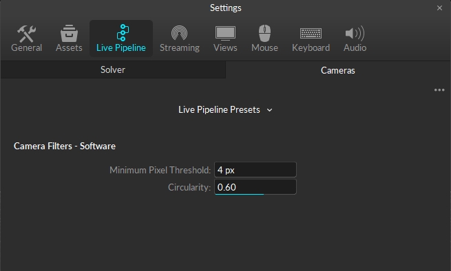
This section of the application settings is used for configuring the 2D filter properties for all of the cameras.
General Settings
Minimum Pixel Threshold
The minimum pixel size of a 2D object, a collection of pixels grouped together, for it to be included in the Point Cloud reconstruction. All pixels must first meet the brightness threshold defined in the Cameras pane in order to be grouped as a 2D object. This can be used to filter out small reflections that are flickering in the view. The default value for the minimum pixel size is 4, which means that there must be 4 or more pixels in a group for a ray to be generated.
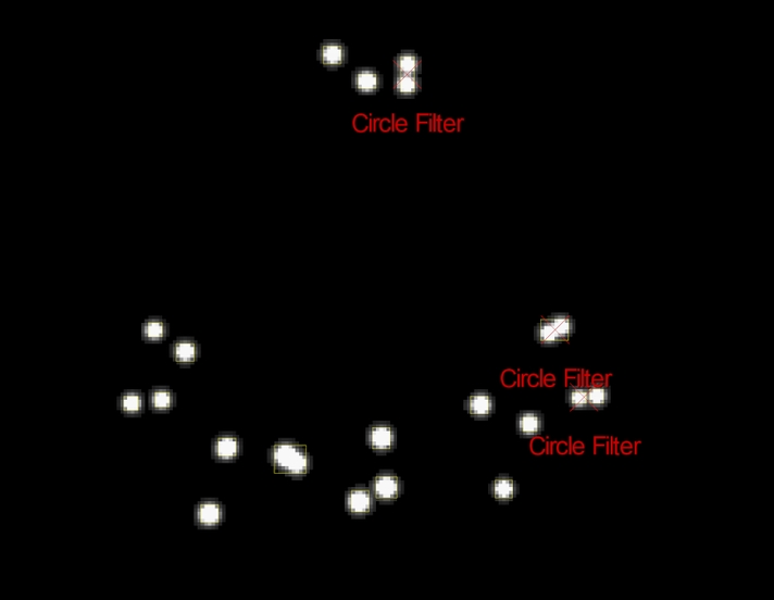
Circularity
This setting sets the threshold of the circularity filter. Valid range is between 0 and 1; with 1 being a perfectly round reflection and 0 being flat. Using this 2D object filter, the software can identify marker reflections using the shape, specifically the roundness, of the group of thresholded pixels. Higher circularity setting will filter out all other reflections that are not circular. It is recommended to optimize this setting so that extraneous reflections are efficiently filtered out while not filtering out the marker reflections.
When using lower resolution cameras to capture smaller markers at a long distance, the marker reflection may appear to be more pixelated and non-circular. In this case, you may need to lower the circularity filter value for the reflection to be considered as a 2D object from the camera view. Also, this setting may need to be lowered when tracking non-spherical markers in order to avoid filtering the reflections.
Camera Advanced Settings
General Settings
Mask Padding
Changes the padding around masks by pixels.
Shutter Offset
Delay this group from sync pulse by this amount.
Synchronizer Control
Controls how the synchronizer operates. Options include:
Force Timely Delivery
Favor Timely Delivery
Force Complete Delivery
Camera Filters - Software
Filter Type
Choose the filter type. Options include:
Size and Roundness
None
Minimum Pixel Threshold
The minimum allowable size of the 2D object (pixels over threshold).
Maximum Pixel Threshold
The maximum allowable size of the 2D object (pixels over threshold).
Camera Filters - Hardware
Intrusion Band
The size of the guard region beyond the object margin for neighbor detection.
Grayscale Floor
The pixel intensity of the grayscale floor (pixel intensity).
Object Margin Diameter
The minimum space (in pixels) between objects before they begin to overlap.
Object Skew
The number of pixels a 2D object is allowed to lean.
Max Aspect Tolerance
The maximum allowable aspect tolerance to process a 2D object (width:height).
Aspect Base
The allowable aspect tolerance for very small objects.
Aspect Step Size
The rate at which the aspect tolerance relaxes as object size increases.
Was this helpful?