# OptiTrack Documentation

## How to Use the User Guide&#x20;

* Use the **Table of Contents** to navigate through the guide.&#x20;
  * In the Desktop view, the Table of Contents appears in the left pane.
  * In the Mobile view, click the Menu icon in the header to display the Table of Contents or to switch between different versions of Motive.

<figure><picture><source srcset="/files/bAzQnXXMNuDPKZ0NYixm" media="(prefers-color-scheme: dark)"><img src="/files/SlazP1MaHGRsK5CBpaUP" alt="" width="375"></picture><figcaption><p>Mobile view header.</p></figcaption></figure>

* Click any Chapter heading to go to that section, or use the <picture><source srcset="/files/1J2MV7Sco9HwDXIuv6QQ" media="(prefers-color-scheme: dark)"><img src="/files/HyCrD8vqd8SHUmnj2dhJ" alt="" data-size="line"></picture> button to display  the chapter's contents.&#x20;
* Quick Links and the Search Bar are always available in the desktop view's page header, or by clicking the 3 dots in the Mobile header:&#x20;

<figure><picture><source srcset="/files/ciPRCjqswqURlwAvxSVb" media="(prefers-color-scheme: dark)"><img src="/files/ZroP7osPxUnTNJVY5HgU" alt=""></picture><figcaption><p>The User Guide Header includes links to popular pages and the Search Bar.</p></figcaption></figure>

* Navigate within a page using the page's Table of Contents on the right. If the page Table of Contents isn't visible, try increasing the size of the browser window.
* Click the version number in between the OptiTrack logo and the Table of Contents to access documentation for earlier versions of Motive.&#x20;

<figure><picture><source srcset="/files/YD2zUl4w2vQTn7D9DQII" media="(prefers-color-scheme: dark)"><img src="/files/FUWvwXQflujDRnz90tdb" alt=""></picture><figcaption><p>Click the version number to change versions.</p></figcaption></figure>

Can't find the information you're looking for, or need additional help? Quick links on the page banner take you directly to:

* Resources on the OptiTrack website [http://www.optitrack.com](http://www.optitrack.com/)
* OptiTrack Support: [https://optitrack.com/support](https://optitrack.com/support/)
* NaturalPoint Forum Archive: [https://forums.naturalpoint.com](https://forums.naturalpoint.com/)
* OptiTrack Discord: <https://discord.com/invite/optitrack>

## Quick Links

Link directly to our most popular pages from the tabs below.&#x20;

{% tabs %}
{% tab title="Getting Started" %}

### Getting Started

* [Quick Start Guide: Getting Started](/quick-start-guides/quick-start-guide-getting-started)
* [Prepare Setup Area](/hardware/prepare-setup-area)
* [Cabling and Load Balancing](/hardware/cabling-and-wiring/cabling-and-load-balancing)
* [Camera Placement](/hardware/camera-placement)
* [Installation and Activation](/motive/installation-and-activation) (with [Licensing](/motive/installation-and-activation#license-activation) information)
* [Aiming and Focusing](/hardware/aiming-and-focusing)
* [Motive Basics](/motive/motive-basics)
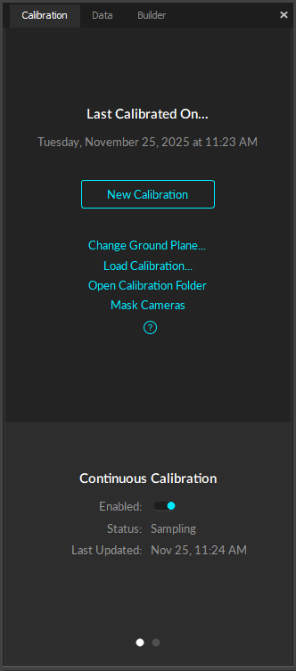
* [Calibration](/motive/calibration)
* [Data Recording](/motive/data-recording)
* [Quick Start Guides](/quick-start-guides)
  {% endtab %}

{% tab title="Hardware" %}

### Hardware

* [Cameras](/hardware/cameras)
* [Camera Mount Structures](/hardware/camera-mount-structures)
* [Quick Start Guide Precision Capture](/quick-start-guides/quick-start-guide-precision-capture)
* [External Device sync guide eSync2](/synchronization/synchronization-hardware/external-device-sync-guide-optihub2)
* [Devices Pane in Motive](/motive-ui-panes/devices-pane)
  {% endtab %}

{% tab title="Asset Tracking" %}

### Asset Tracking

* [Markers](/motive/markers)
* [Assets](/motive/assets)
* [Rigid Body Tracking](/motive/rigid-body-tracking)
* [Skeleton Tracking](/motive/skeleton-tracking)
* [Trained Markersets](/motive/trained-markersets)
  {% endtab %}

{% tab title="Active Tracking" %}

### Active Tracking

* [Quick Start Guide: Active Marker Tracking](/quick-start-guides/quick-start-guide-active-marker-tracking)
* [Active Marker Tracking](/active-classic/active-marker-tracking)
* [IMU Sensor Fusion](/motive/imu-sensor-fusion)
  {% endtab %}
  {% endtabs %}

{% tabs %}
{% tab title="Streaming" %}

### Streaming&#x20;

* [Data Streaming](/motive/data-streaming)
* [NatNet 4.0](/developer-tools/natnet-sdk/natnet-4.5)
* [OptiTrack Unity Plugin](/plugins/optitrack-unity-plugin)
* [Unreal Engine Plugin](/plugins/optitrack-unreal-engine-plugin)
* [Unreal Engine OptiTrack Live Link Plugin](/plugins/optitrack-unreal-engine-plugin/unreal-engine-optitrack-live-link-plugin)
  {% endtab %}

{% tab title="Processing Takes" %}

### Processing Takes

* [Data Editing](/motive/data-editing)
* [Labeling](/motive/labeling)
* [Data Export](/motive/data-export)
  {% endtab %}

{% tab title="Movement Sciences" %}

### Movement Sciences

* [Movement Sciences Markersets](/movement-sciences/movement-sciences-markersets)
* [NI-DAQ Setup](/movement-sciences/movement-sciences-hardware/ni-daq-setup)
* [Movement Sciences Hardware](/movement-sciences/movement-sciences-hardware)
  {% endtab %}
  {% endtabs %}


# WHAT'S NEW


# What's New in Motive 3.5

Highlights of new features in Motive 3.5

{% embed url="<https://youtu.be/bGtbZ7snhe0>" %}

## ActiveIO

In our next generation of technology, ActiveIO takes tracking to the next level with automatic firmware updates, input and output (IO) of data from the tags to give battery life and other metrics, as well as all of the classic on/off (IO) blinking markers to uniquely identify individual markers.

See the [ActiveIO Configuration](/activeio/activeio-configuration) page for details on how to setup and use your ActiveIO device in Motive. See The [ActiveIO Hardware section](/activeio/activeio-hardware) for details on each device, including quick start and setup instructions, indicator lights, and product specifications.&#x20;

## PrimeX 260 Camera

The new [PrimeX 260](/hardware/cameras/ethernet-cameras/primex-260) is our camera with the most MegaPixels yet. With 26 MegaPixels, this camera is ideal for premium configurations where only the highest level of accuracy and precision is acceptable.

## Deadzone Smoothing

This new option for rigid bodies detects when the movement for an object has gone below a specified threshold. Once below that threshold, the movement of the rigid body is made completely static. This is most useful when projecting the angle of the rigid bodies long distances like in InCamera VFX workflows.

## New Data Streaming Types

To support ActiveIO we have added the ability to stream additional data types.&#x20;

#### **Raw IMU data (inertial measurement unit)**

Streaming of raw IMU data from ActiveIO devices allows for workflows where sensor fusion can be done on the client side.

#### **GPIO data (General Purpose Input/Output)**&#x20;

This unlocks workflows where button inputs are activated on ActiveIO devices, then sent to game engines or client applications where actions in the game can occur.

#### **Anchor Markers**&#x20;

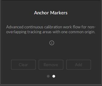
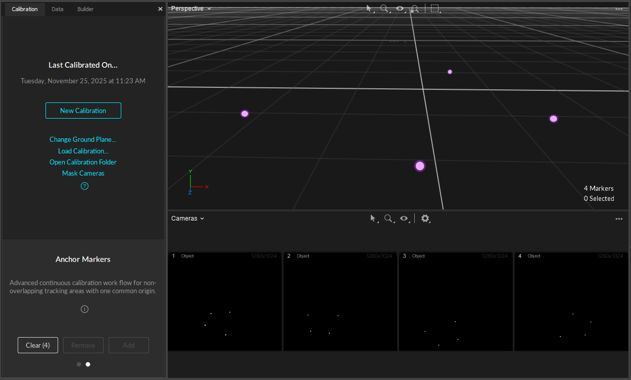
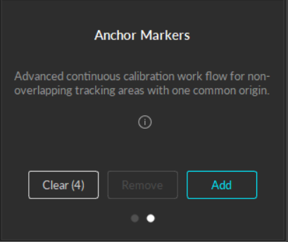
Streaming of Anchor Markers allows users to better remotely monitor system health using a NatNet Client. A new example client for how to do this is included with NatNet 4.5.

For more detail, please see the [Data Streaming](/motive/data-streaming) page.&#x20;

## Other Highlights

**USD Export** - Export animation files to the OpenUSD format for importing into game engines and other workflows like the NVIDIA Omniverse.

**STL Attached Geometries** - Enable CAD workflows by attaching STL files onto rigid bodies for better visualization of your engineering project.

**Passive or Active Only Modes** - Added back the ability to have Passive Only and Active Only markers.

{% hint style="info" %}
**For More Information:**

Visit our website for more detail on the new version:

* What's New: <https://www.optitrack.com/software/motive/>
* Change log and Download link: <https://www.optitrack.com/support/downloads/>
  {% endhint %}


# QUICK START GUIDES


# Quick Start Guide: Getting Started

Welcome to the **Quick Start Guide: Getting Started**!

\
This guide provides a quick walk-through of installing and using OptiTrack motion capture systems. Key concepts and instructions are summarized in each section of this page to help you get familiarized with the system and get you started with the capture experience.

Note that Motive offers features far beyond the ones listed in this guide, and the capability of the system can be further optimized to fit your specific capture applications using the additional features. For more detailed information on each workflow, read through the corresponding workflow pages in this wiki: [hardware setup](/hardware) and [software setup](/motive).

{% embed url="<https://youtu.be/HyrHhaRVOaM?si=bN2caz733MdtR8OE>" %}

## Hardware Setup

### Preparing the Capture Area

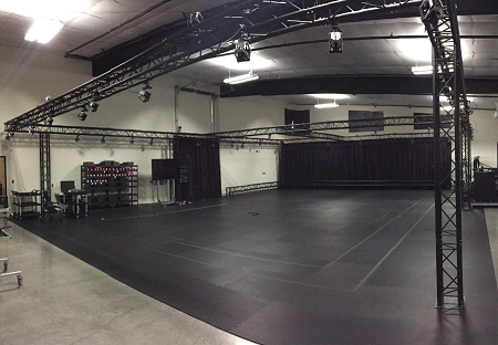
For best tracking results, you need to prepare and clean up the capture environment before setting up the system. First, remove unnecessary objects that could block the camera views. Cover open windows and minimize incoming sunlight. Avoid setting up a system over reflective flooring since IR lights from cameras may get reflected and add noise to the data. If this is not an option, use rubber mats to cover the reflective area. Likewise, items with reflective surfaces or illuminating features should be removed or covered with non-reflective materials in order to avoid extraneous reflections.

![](/files/Fbiro9WYRVGZTm3n7wNu)

**Key Checkpoints for a Good Capture Area**

* Minimize ambient lights, especially sunlight and other infrared light sources.
* Clean capture volume. Remove unnecessary obstacles within the area.
* Tape, or Cover, remaining reflective objects in the area.

**See Also:** [Hardware Setup](/hardware) workflow pages.

### Cabling and Load Balancing

#### Ethernet Camera System

*Ethernet Camera Models: PrimeX series and SlimX 13 cameras. Follow the below wiring diagram and connect each of the required system components.*

{% tabs %}
{% tab title="Single PoE Switch" %}
![Click image to enlarge.](/files/CQhmjVDBY1w6QZrOdMBb)
{% endtab %}

{% tab title="Multiple PoE Switch (High camera counts)" %}
![Click image to enlarge.](/files/nm4tvRCeUzfoOoNnmF6m)

* **Uplink Switch:** For systems with higher camera counts that uses multiple PoE switches, use an uplink Ethernet switch to link and connect all of the switches to the Host PC. In the end, the switches must be connected in a star topology with the uplink switch at the central node connecting to the host PC. **NEVER** daisy chain multiple PoE switches in series because doing so can introduce latency to the system.
* **High Camera Counts:** For setting up more than 24 Prime series cameras, we recommend using a 10 Gigabit uplink switch and connecting it to the host PC via an Ethernet cable that supports 10 Gigabit transfer rate — Cat6a or above. This will provide larger data bandwidth and reduce the data transfer latency.
  {% endtab %}

{% tab title="Switch Power Budget and Camera Power Requirements" %}

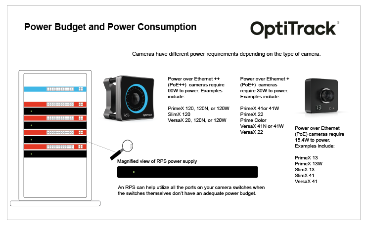
<figure><img src="/files/qfgNOYSdchk6cKTGPrAu" alt="An illustration of the Power Budget and Power Consumption requirements for each OptiTrack camera."><figcaption><p>Click image to enlarge.</p></figcaption></figure>

#### **PoE Switch Requirements**

PoE switches are categorized based on the maximum power level that individual ports can supply. The table below shows the power output of the various types of PoE switches and lists the current camera models that require each power level.&#x20;

<table><thead><tr><th width="151">PoE Type</th><th width="159">Max Watts / Port</th><th>Cameras</th></tr></thead><tbody><tr><td>PoE</td><td>15.4W</td><td>PrimeX 13 or 13W, SlimX 13, SlimX 41, VersaX 41</td></tr><tr><td>PoE+</td><td>30W</td><td>PrimeX 22, PrimeX 41 or 41W, Prime Color, SlimX 120, VersaX 41N, 41W, or 120</td></tr><tr><td>PoE++</td><td>90W</td><td>PrimeX 120, VersaX 120N, or 120W</td></tr></tbody></table>

{% hint style="warning" %}
Not all PoE++ switches are the same. **PoE++ Type 3** switches provide only 60W of power per port, which is insufficient to power a PrimeX 120 camera. A **PoE++ Type 4** switch supplies 100W per port, providing the optimum power to each PrimeX 120 on the switch.&#x20;
{% endhint %}

For network switches provided by OptiTrack, refer to the label for the number of cameras supported for each switch.
{% endtab %}
{% endtabs %}

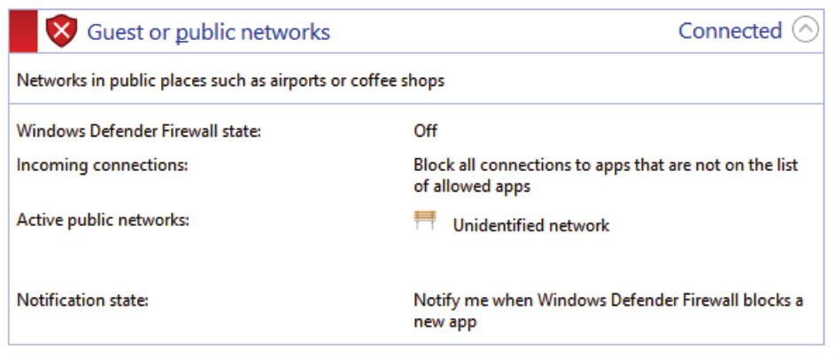
* **Connect PoE Switch(es) to the Host PC:** Start by connecting a PoE switch into the host PC via an Ethernet cable. Since the camera system takes up a large amount of data bandwidth, the Ethernet camera network traffic must be separated from the office/local area network. If the computer used for capture is connected to an existing network, you will need to use a second Ethernet port or add-on network card for connecting the computer to the camera network. When you do, make sure to turn off your computer's firewall for the particular network under Windows Firewall settings.
* **Connect the Ethernet Cameras to the PoE Switch(es):** Ethernet cameras connect to the host PC via PoE/PoE+ switches using Cat 6 or above, Ethernet cables.
* **Power the Switches:** The switch must be powered in order to power the cameras. To completely shut down the camera system, the network switch needs to be powered off.
* **Ethernet Cables:** Ethernet cable connection is subject to the limitations of the PoE (Power over Ethernet) and Ethernet communications standards, meaning that the distance between camera and switch can go up to about 100 meters when using Cat 6 cables (Ethernet cable type Cat5e or below is not supported). For best performance, do not connect devices other than the computer to the camera network. Add-on network cards should be installed if additional Ethernet ports are required.
* **External Sync:** If you wish to connect external devices, use the eSync synchronization hub. Connect the eSync into one of the PoE switches using an Ethernet cable, or if you have a multi-switch setup, plug the eSync into the aggregation switch.

#### **Ethernet Cable Requirements**

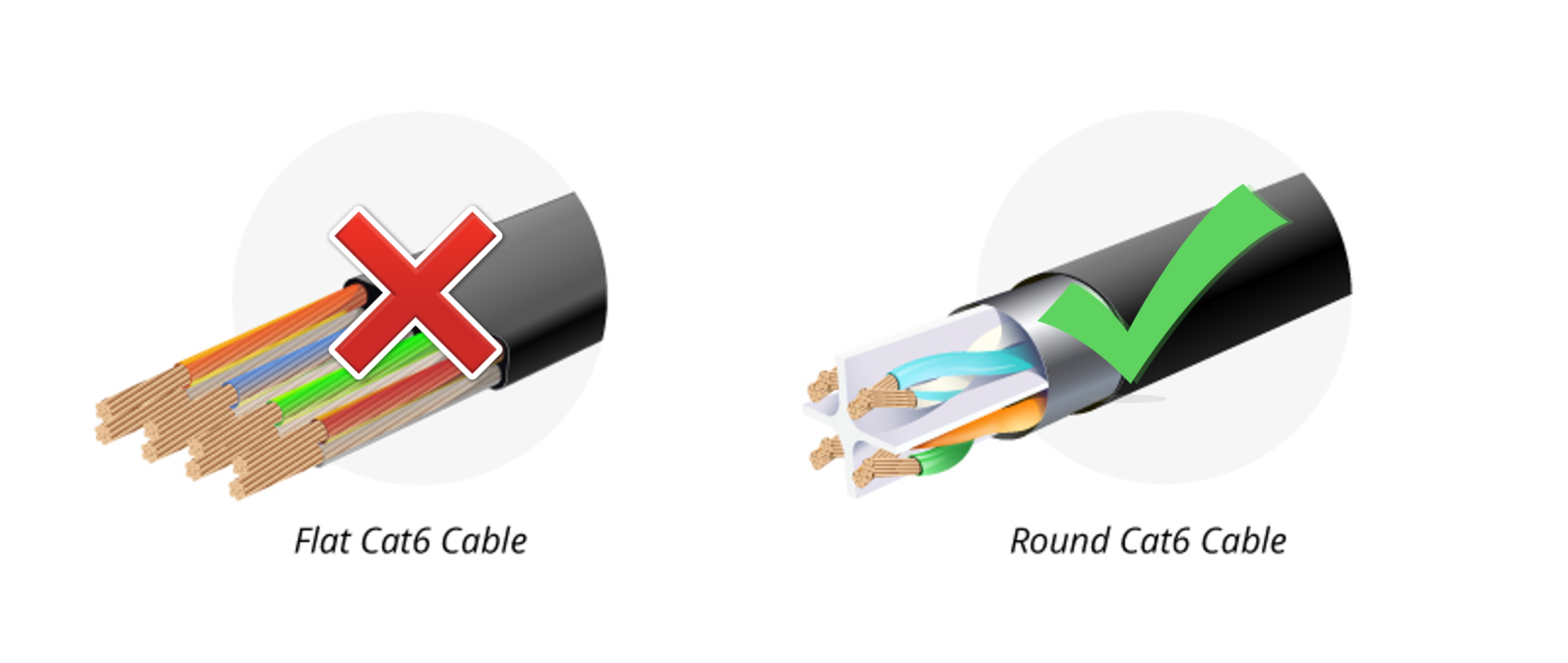
There are multiple categories for Ethernet cables, and each has different specifications for maximum data transmission rate and cable length. For an Ethernet based system, category 6 or above Gigabit Ethernet cables should be used. 10 Gigabit Ethernet cables – Cat6a or above— are recommended in conjunction with a 10 Gigabit uplink switch for the connection between the uplink switch and the host PC in order to accommodate for the high data traffic.

Also, please use a cable that has electromagnetic interference shielding on it. If cables without the shielding are used, cables that are close to each other could interfere and cause the camera to stall in Motive.

#### **Electromagnetic Shielding**

We recommend using only cables that have electromagnetic interference shielding. If unshielded cables are used, cables in close proximity to each other have the potential to create data transfer interference and cause cameras to stall in Motive.

{% hint style="danger" %}
Unshielded cables do not protect the cameras from Electrostatic Discharge (ESD), which can damage the camera. Do not use unshielded cables in environments where ESD exposure is a risk.&#x20;
{% endhint %}

**See Also:** [Network setup](/hardware/cabling-and-wiring) page.

### Placing and Aiming Cameras

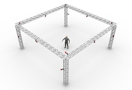
Optical motion capture systems utilize multiple 2D images from each camera to compute, or [reconstruct](/motive/reconstruction-and-2d-mode), corresponding 3D coordinates. For best tracking results, cameras must be placed so that each of them captures unique vantage of the target capture area. Place the cameras circumnavigating around the capture volume, as shown in the example below, so that markers in the volume will be visible by at least two cameras at all times. Mount cameras securely onto stable structures (e.g. truss system) so that they don't move throughout the capture. When using tripods or camera stands, ensure that they are placed in stable positions. After placing cameras, aim the cameras so that their views overlap around the region where most of the capture will take place. Any significant camera movement after system calibration may require [re-calibration](/motive/calibration). Cable strain-relief should be used at the camera end of camera cables to prevent potential damage to the camera.

*See Also:* [Camera Placement](/hardware/camera-placement) and [Camera Mount Structures](/hardware/camera-mount-structures) pages.

![](/files/GHatO7DusLGdvkOVHHuU) ![](/files/qASPeTqWAKRHYyMJYmrD) ![](/files/7Y1LeJj5Azy2bjWYXZQA)

### Lens Focus

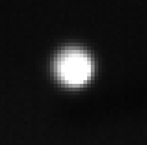
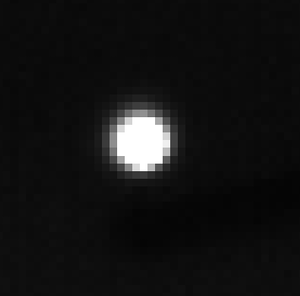
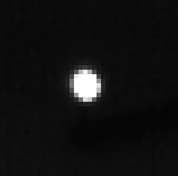
In order to obtain accurate and stable tracking data, it is very important that all of the cameras are correctly focused to the target volume. This is especially important for close-up and long-range captures. For common tracking applications in general, focus-to-infinity should work fine, however, it is still important to confirm that each camera in the system is focused.

To adjust or to check camera focus, place some markers on the target tracking area. Then, set the camera to raw grayscale mode, increase the exposure and LED settings, and then Zoom onto one of the retroreflective markers in the capture volume and check the clarity of the image. If the image is blurry, adjust the camera focus and find the point where the marker is best resolved.

*See Also:* [Aiming and Focusing](/hardware/aiming-and-focusing) page.

![Out of focus](/files/6EvJpEzQ3PWv3mNc7UA6) ![Moderately in focus](/files/mFm1uLXDtkWyfFw8PGKM) ![In focus](/files/DAU5efnzWuJHZ4eQXUGK)

## Software Setup

### Host PC Requirements

In order to properly run a motion capture system using Motive, the host PC must satisfy the minimum system requirements. Required minimum specifications vary depending on sizes of mocap systems and types of cameras used. Consult our [Sale Engineers](http://optitrack.com/contact/), or use the [Build Your Own feature](http://optitrack.com/systems/) on our website to find out host PC specification requirements.

### Motive Installation

Motive is a software platform designed to control motion capture systems for various tracking applications. Motive not only allows the user to calibrate and configure the system, but it also provides interfaces for both capturing and processing of 3D data. The captured data can be recorded or live-streamed into other pipelines.

*If you are new to Motive, we recommend you to read through* [*Motive Basics*](/motive/motive-basics) *page after going through this guide to learn about basic navigation controls in Motive.*

**Motive Activation Requirements**

The following items are required to activate Motive. Please note that the valid duration of the Motive license must be later than the release date of the version that you are activating. If the license is expired, please update the license or use an older version of Motive that was released prior to the license expiration date.

* Motive 3.x license
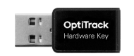
* USB Security or Hardware Key

**Host PC Requirements**

Required PC specifications may vary depending on the size of the camera system. Generally, you will be required to use the recommended specs with a system with more than 24 cameras.

| Recommended                                                                                                                                                                                                                                                                                                       | Minimum                                                                                                                                                                                                                                                  |
| ----------------------------------------------------------------------------------------------------------------------------------------------------------------------------------------------------------------------------------------------------------------------------------------------------------------- | -------------------------------------------------------------------------------------------------------------------------------------------------------------------------------------------------------------------------------------------------------- |
| <ul><li>OS: Windows 10, 11 (64-bit)</li><li>CPU: Intel i7 or better, 3+ GHz</li><li>RAM: 16GB of memory</li><li>GPU: GTX 1050 or better with the latest drivers and support for OpenGL 3.2+</li><li>USB Port: For a Security Key, USB C or USB A with an adapter. For a Hardware Key, USB A is required</li></ul> | <ul><li>OS: Windows 10, 11 (64-bit)</li><li>CPU: Intel i7, 3+ GHz</li><li>RAM: 8GB of memory</li><li>GPU that supports OpenGL 3.2+</li><li>USB Port: For a Security Key, USB C or USB A with an adapter. For a Hardware Key, USB A is required</li></ul> |

{% hint style="danger" %}
The PC specifications are going to heavily depend on the intensity of your application (i.e. animation vs. movement sciences, etc.). If you're unsure of whether or not your computer specifications are adequate for your application, please reach out to either our [Sales ](https://optitrack.com/contact/)or [Support](https://optitrack.com/support/#contact-support) teams.&#x20;
{% endhint %}

**Download and Install**

To install Motive, download the Motive software installer from the [Motive Download Page](http://www.naturalpoint.com/optitrack/downloads/motive.html), then run the installer and follow its prompts.

{% hint style="info" %}
**Note:** Anti-virus software can interfere with Motive's ability to communicate with cameras or other devices, and it may need to be disabled or configured to allow the device communication to properly run the system.
{% endhint %}

**License Activation Steps**

1. Insert the **USB Security Key** into a USB-C port on the computer. If needed, you can also use a USB-A adapter to connect. If using a **USB Hardware Key**, insert it into a USB-A port.&#x20;
2. Launch Motive.
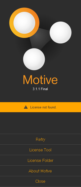
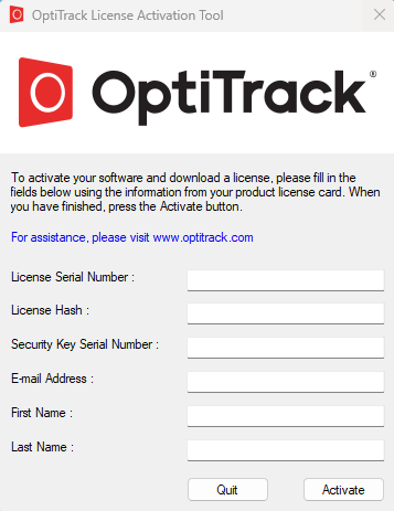
3. Activate your software using the *License Tool*, which can be accessed in the Motive splash screen. You will need to input the License Serial Number and the Hash Code for your license.
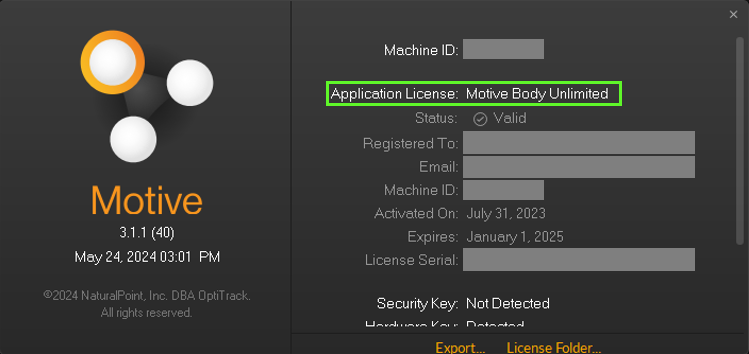
4. After activation, the License tool will place the license file associated to the USB Security Key in the License folder. For more license activation questions, visit [Licensing FAQs](http://optitrack.com/support/faq/licensing.html) or contact our [Support](http://optitrack.com/support/).

{% hint style="danger" %}
When connecting either the Security Key or Hardware Key into the computer, please avoid sharing the USB controller with other USB devices that may transmit a large amount of data frequently. For example, if you have external devices (e.g. Force Plates, NI-DAQ) that communicate via USB, connect those devices to a separate USB controller so they don't interfere with the Security or Hardware Key.
{% endhint %}

## First Launch

By default, Motive will start on the calibration layout with all the necessary panes open. Using this layout, you can calibrate the camera system and construct a 3D tracking volume. The layout may be slightly different for certain camera models or software licenses.

![](/files/kWxCUN4LqDHBT9Pk0JmN)

The following panes will be open:

| UI Name                                                                            | Description                                                                                                                                                                                                                                                                                                                                                                                                                                                                                                                                                                                                                                                                                                                                                                                                                                                                                                                                                                                                                                                                                                                                                                                                                                                                                                          |
| ---------------------------------------------------------------------------------- | -------------------------------------------------------------------------------------------------------------------------------------------------------------------------------------------------------------------------------------------------------------------------------------------------------------------------------------------------------------------------------------------------------------------------------------------------------------------------------------------------------------------------------------------------------------------------------------------------------------------------------------------------------------------------------------------------------------------------------------------------------------------------------------------------------------------------------------------------------------------------------------------------------------------------------------------------------------------------------------------------------------------------------------------------------------------------------------------------------------------------------------------------------------------------------------------------------------------------------------------------------------------------------------------------------------------- |
| [**Devices Pane**](/motive-ui-panes/devices-pane)                                  | Connected cameras will be listed under the [Devices pane](/motive-ui-panes/devices-pane). This panel is where we can configure settings (FPS, exposure, LED, and etc.) for each camera and decide whether to use selected cameras for 3D tracking [![Camera TrackingMode.png](https://v30.wiki.optitrack.com/images/1/1b/Camera_TrackingMode.png)](https://v30.wiki.optitrack.com/index.php?title=File:Camera_TrackingMode.png) or reference [![Camera ReferenceMode 21.png](https://v30.wiki.optitrack.com/images/3/39/Camera_ReferenceMode_21.png)](https://v30.wiki.optitrack.com/index.php?title=File:Camera_ReferenceMode_21.png) videos. Only the cameras that are set to tracking mode will contribute to reconstructing 3D coordinates. Cameras in [reference mode](/motive/camera-video-types) capture grayscale images for reference purposes only. The Devices pane can be accessed under the View tab in Motive or by clicking [![Tb10.png](https://v30.wiki.optitrack.com/images/a/ad/Tb10.png)](https://v30.wiki.optitrack.com/index.php?title=File:Tb10.png) icon on the main toolbar.                                                                                                                                                                                                                |
| [**Properties pane**](/motive-ui-panes/properties-pane)                            | <p>When an object is selected in Motive, all of its related properties will be listed under the <a href="/pages/fRTGYzppUP7BFWX4kZvX">Properties pane</a>. For example, when a <a href="/pages/VXaLYsygIZJeV4ywZLnu">skeleton asset</a> is selected in the 3D viewport, its corresponding <a href="/pages/9sCmF5h7vT0wBgLlv8Fx">skeleton properties</a> will get listed in this pane, and we can view the settings and configure them as needed.</p><p>Likewise, this pane is also used to view the properties of the cameras and any other connected devices that are listed in the <a href="/pages/vkRPsTCayMHrb7EGuCoB">Devices pane</a>.</p><p>and recorded <em>Takes</em> to view and configure their properties.</p><p>This pane will be used in almost all of the workflows. The Devices pane can be accessed under the View tab in Motive or by clicking <a href="https://v30.wiki.optitrack.com/index.php?title=File:Toolbar_Properties_Icon.png"><img src="https://v30.wiki.optitrack.com/images/d/d1/Toolbar_Properties_Icon.png" alt="Toolbar Properties Icon.png"></a> icon from the main toolbar.</p>                                                                                                                                                                                                  |
| [**View pane (Perspective Viewport)**](/motive-ui-panes/viewport#perspective-view) | <p>The top <a href="/pages/M5aZ1GU2ITDvosyeIsA9">viewport</a> is where 3D data is shown in Motive. Here, you can view and analyze 3D data within a calibrated capture volume. This panel will be used during the live capture and also in the playback of recorded data. In the perspective viewport, you can select any objects in the capture volume, use the context menu to perform actions, or use the <a href="/pages/fRTGYzppUP7BFWX4kZvX">Properties pane</a> to view and modify the associated properties.</p><p>You can use the dropdown menu at the top-left corner to switch between different viewports, and you can also use the <a href="https://v30.wiki.optitrack.com/index.php?title=File:ContextMenu_dotdotdot.png"><img src="https://v30.wiki.optitrack.com/images/c/c4/ContextMenu_dotdotdot.png" alt="ContextMenu dotdotdot.png"></a> button at the top-right corner to split the viewport into multiple. If desired, an additional View pane can be open by opening up a Viewer pane under the <a href="/pages/i1RA3nz7bwNK2LXPfCty">View tab</a> or by clicking <a href="https://v30.wiki.optitrack.com/index.php?title=File:Toolbar_Views_30.png"><img src="https://v30.wiki.optitrack.com/images/a/a5/Toolbar_Views_30.png" alt="Toolbar Views 30.png"></a> icons on the main toolbar.</p> |
| [**View pane (Cameras Viewport)**](/motive-ui-panes/viewport#cameras-view)         | The bottom viewport is the Cameras viewport. Here, you can monitor the view of each camera in the system and apply [*mask filters*](/motive/calibration). This pane is also used to examine markers, or IR lights, seen by the cameras in order to examine how the 2D data is processed and reconstructed into 3D coordinates.                                                                                                                                                                                                                                                                                                                                                                                                                                                                                                                                                                                                                                                                                                                                                                                                                                                                                                                                                                                       |
| [**Calibration pane**](/motive-ui-panes/calibration-pane)                          | The Calibration pane is used in camera calibration process. In order to compute 3D coordinates from captured 2D images, the camera system needs to be calibrated first. All tools necessary for calibration is included within the Calibration pane, and it can also be accessed under the [View tab](/motive-ui-panes/toolbar-command-bar) or by clicking [![Toolbar Calib 20.png](https://v30.wiki.optitrack.com/images/c/c9/Toolbar_Calib_20.png)](https://v30.wiki.optitrack.com/index.php?title=File:Toolbar_Calib_20.png) icon on the main toolbar.                                                                                                                                                                                                                                                                                                                                                                                                                                                                                                                                                                                                                                                                                                                                                            |
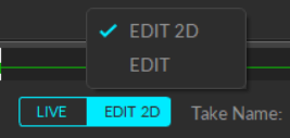
| [**Control Deck**](/motive-ui-panes/control-deck)                                  | The Control Deck, located at bottom of Motive, is where you can control recording (Live Mode) or playback (Edit Mode) of capture data. In the Live mode, you can use the control deck to start recording and assign filename for the capture. In the Edit mode, you can use this pane to control the playback of recorded *Take(s)*.                                                                                                                                                                                                                                                                                                                                                                                                                                                                                                                                                                                                                                                                                                                                                                                                                                                                                                                                                                                 |

{% hint style="info" %}
**See Also:** List of UI pages from the [Motive ](/motive)section of the wiki.
{% endhint %}

### Viewport Navigation

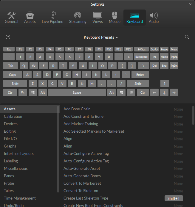
Use the following controls for navigating throughout the 2D and 3D viewports in Motive. Most of the navigation controls are customizable, including both mouse actions and [hotkeys](/motive/motive-hotkeys). These mouse and keyboard controls can be customized through the [Application Settings](/motive-ui-panes/settings) panel.

| Function                        | Default Control             |
| ------------------------------- | --------------------------- |
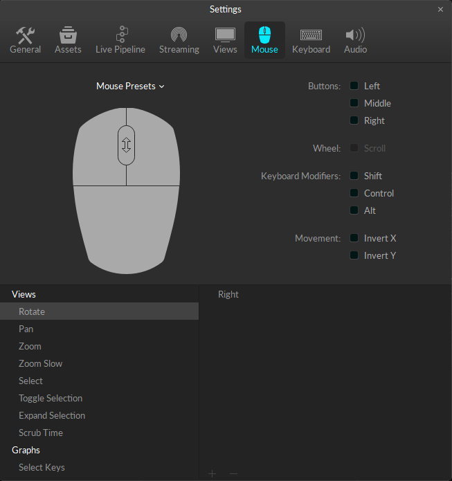
| Rotate view                     | Right + Drag                |
| Pan view                        | Middle (wheel) click + drag |
| Zoom in/out                     | Mouse Wheel                 |
| Select in View                  | Left mouse click            |
| Toggle selection in View        | CTRL + left mouse click     |
| Show one viewport               | Shift + 1                   |
| Horizontally split the viewport | Shift + 2                   |

### Camera Settings

Now that the cameras are connected and showing up in Motive, the next step is to configure the camera settings. Appropriate camera settings will vary depending on various factors including the capture environment and tracked objects. The overall goal is to configure the settings so that the marker reflections are clearly captured and distinguished in the 2D view of each camera. For a detailed explanation on individual settings, please refer to the [Devices pane](/motive-ui-panes/devices-pane) page.

To check whether the camera setting is optimized, it is best to check both the grayscale mode images and tracking mode (Object or Precision) images and make sure the marker reflection stands out from the image. You switch a camera into grayscale mode either in Motive or by using the [Aim Assist](/hardware/aiming-and-focusing) button for supported cameras. In Motive, you can right-click on the [Cameras Viewport](/motive-ui-panes/viewport) and switch the video mode in the context menu, or you can also change the video mode through the [Properties pane](/motive-ui-panes/properties-pane).

**Exposure Setting**

The exposure setting determines how long the camera imagers are exposed per each frame of data. With longer the exposure, more light will be captured by the camera, creating the brighter images that can improve visibility for small and dim markers. However, high exposure values can introduce false markers, larger marker blooms, and marker blurring – all of which can negatively impact marker data quality. It is best to minimize the exposure setting as long as the markers are clearly visible in the captured images.

![Adjusting camera settings using the Devices pane. This can also be done through the Properties pane as well.](/files/MlZAhKPoVnjQLrNzNd3l) ![Retroreflective markers shown on the grayscale image.](/files/wwbJY4ZMx4qGQ1dOpBTq)

## System Calibration

{% hint style="info" %}
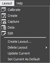
**Tip:** For the calibration process, click the *Layout → Calibrate* menu (CTRL + 1) to access the calibration layout.
{% endhint %}

In order to start tracking, all cameras must first be calibrated. Through the camera calibration process, Motive computes position and orientation of cameras (extrinsic) as well as amounts of lens distortions in captured images (intrinsics). Using the calibration results, Motive constructs a 3D capture volume, and within this volume, motion tracking is accomplished. All of the calibration tools can be found under the [Calibration pane](/motive/calibration). Read through the [Calibration](/motive/calibration) page to learn about the calibration process and what other tools are available for more efficient workflows.

**See Also:** [Calibration](/motive/calibration) page.

{% hint style="warning" %}
**Duo/Trio Tracking Bars:** The camera calibration is not needed for Duo/Trio Tracking bars. The cameras are pre-calibrated using the fixed camera placements. This allows the tracking bars to work right out of the box without the calibration process. To adjust the ground plane, used the [Coordinate System Tools](/hardware/cameras/usb-cameras/adjusting-global-origin-for-tracking-bars) in Motive.
{% endhint %}

### Calibration Steps

**Starting a Calibration**

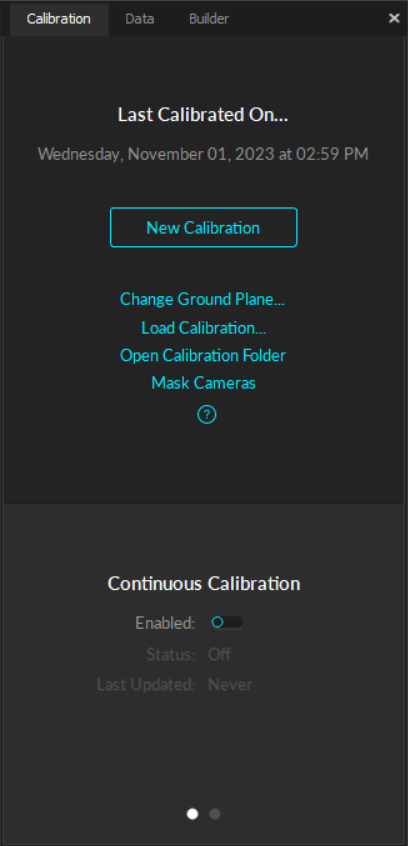
To start a system calibration, open the [Calibration Pane](/motive/calibration). Under the Calibration pane, you can choose to start a new calibration or to modify the existing one. For this guide, click New Calibration for a fresh calibration.

![Starting a new calibration.](/files/JeAaS69MZoXnn469qwXd)

**Masking**

Before the system calibration, any extraneous reflections or unnecessary markers should ideally be removed or covered so that they are not seen by the cameras. However, it may not always be possible to remove all of them. In this case, these extraneous reflections can be ignored by applying masks over them during the calibration.

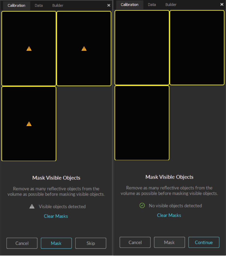
1. Check the calibration pane to see if any of the cameras are seeing extraneous reflections or noise in their view. A warning sign will appear over these cameras.
2. Check the [camera view](/motive-ui-panes/viewport) of the corresponding camera to identify where the extraneous reflection is coming from, and if possible, remove them from the capture volume or cover them so that the cameras do not see them.
3. If reflections still exist, click *Mask* to automatically apply masks over all of the reflections detected in the camera views.
4. Once all of the reflections have been masked or removed, click *Continue* to proceed to the wanding step.

![Masking in camera view.](/files/NgBsnkTRLTRJKB4gfQcF)

**Wanding**

In the wanding stage, we will use the Calibration Wand to collect wanding samples that will be used for calibrating the system.

![Performing calibration wanding for a system with 6 cameras](https://v30.wiki.optitrack.com/images/thumb/6/6a/Calibration_Wanding2_30.gif/200px-Calibration_Wanding2_30.gif)

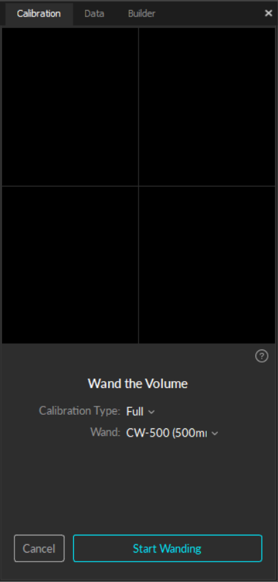
1. Set the [Calibration Type](/motive/calibration) to *Full*.
2. Under the Wand settings, specify the wand that you will be used to calibrate the volume. *It is very important to input the matching wand size here. When an incorrect dimension is given to Motive, the calibrated 3D volume will be scaled incorrectly.*
3. Click *Start Wanding* to start collecting the wanding sample.
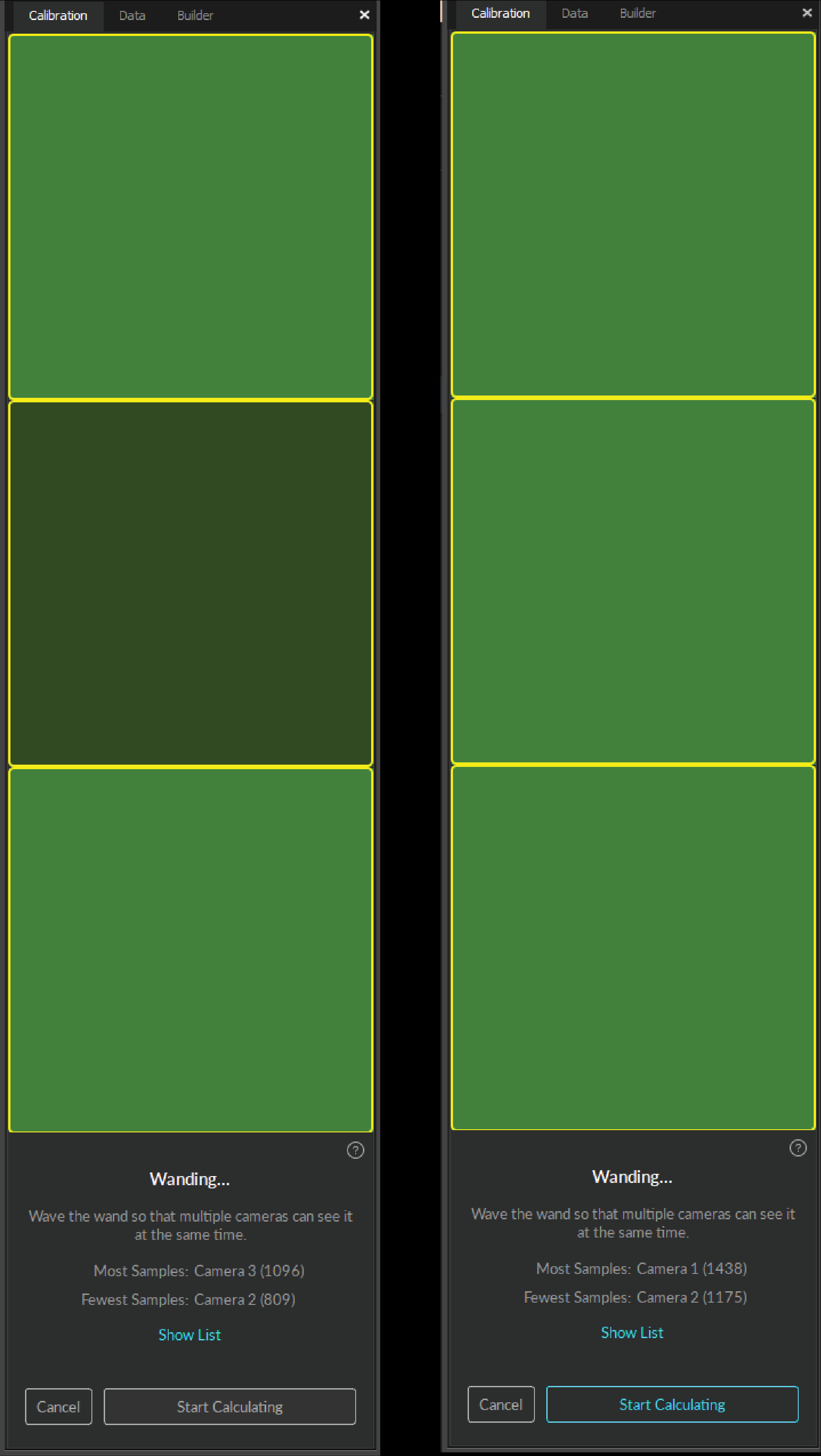
4. Once the wanding process starts. Bring your calibration wand into the capture volume and start waving the wand gently across the entire capture volume. Gently draw figure-eight repetitively with the wand to collect samples at varying orientations and cover as much space as possible for sufficient sampling. Wanding trails will be shown in colors on the [2D View](/motive-ui-panes/viewport). A grid/table displaying the status of the wanding process will show up in the Calibration pane to monitor the progress.
5. As each camera collects the wanding samples, the camera grid representing the wanding status of each camera will start changing its color to bright green. This provides visual feedback on whether sufficient samples have been collected by each camera. Wave the wand until all boxes are filled with bright green color.
6. Once enough samples have been collected, press the Start Calculation button to start calibrating. The calculation may take a few minutes to complete.
7. When the calculation is finished, its results will get displayed. If the overall result is acceptable, click *Continue* to proceed to setting up the ground. If the result is not satisfactory, click *Cancel* and go through the wanding once more.

{% hint style="info" %}
**Wanding tips**

* For best results, collect wand samples evenly and comprehensively throughout the volume, covering both low and high elevations. If you wish to start calibrating inside the volume, cover one of the markers and expose it wherever you wish to start wanding. When at least two cameras detect all the three markers while no other reflections are present in the volume, the wand will be recognized, and Motive will start collecting samples.
* Sufficient sample count for the calibration may vary for different sized volumes, but in general, collect 2500 \~ 6000 samples for each camera. Once a sufficient number of samples has been collected, press the button under the Calibration section.
* During the wanding process, each camera needs to see only the 3-markers on the calibration wand. If any of the cameras are detecting extraneous reflections, go back to the masking step to mask them.
*

{% endhint %}

**Setting the Ground Plane**

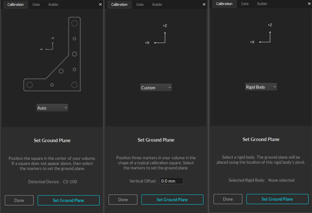
Now that all of the cameras have been calibrated, the next step is to define the ground plane of the capture volume.

![CS-400 calibration square](https://v30.wiki.optitrack.com/images/thumb/2/23/Calib_Square.jpg/200px-Calib_Square.jpg)

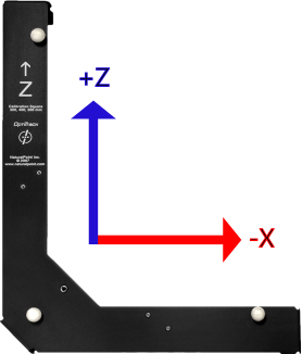
1. Place a [Calibration Square](/motive/calibration/calibration-squares) inside the capture volume. Position the square so that the vertex marker is placed directly over the desired global origin.
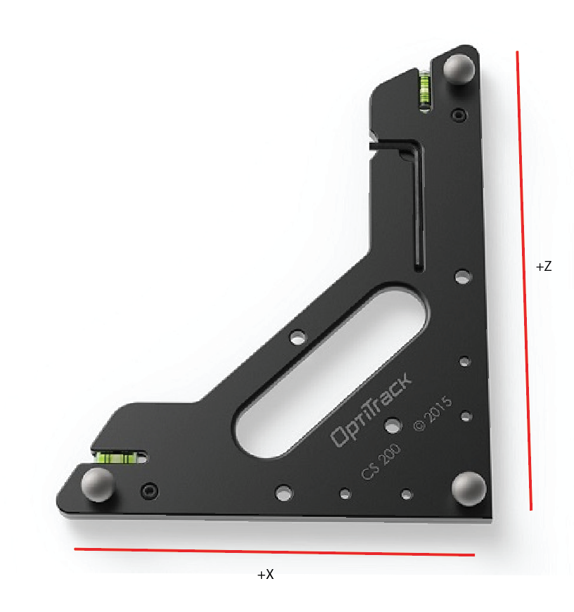
2. Orient the calibration square so that the longer arm is directed towards the desired +Z axes and the shorter arm is directed towards the desired +X axes of the volume. Motive uses the y-up right-hand coordinate system.
3. Level the calibration square parallel to the ground plane.
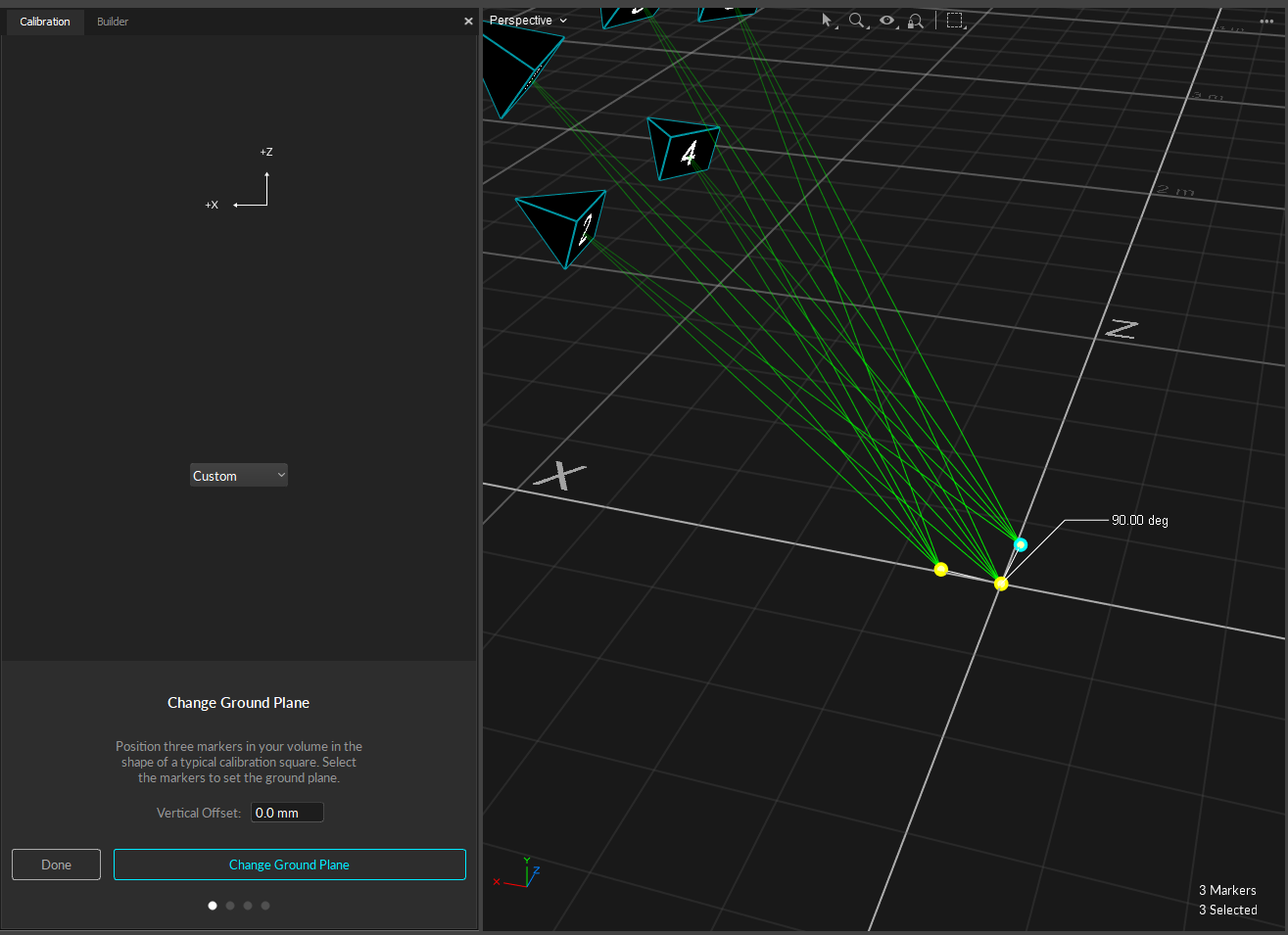
4. At this point, the Calibration pane should detect which calibration square has been placed in the tracking volume. If not, you may want to specifically select the three markers on the calibration square from the [3D view](/motive-ui-panes/viewport) in Motive.
5. Click *Set Ground Plane* to complete the calibration.

## Capture Setup

Once the camera system has been calibrated, Motive is ready to collect data. But before doing so, let's prepare the session folders for organizing the capture recordings and define the trackable assets, including Rigid Body and/or Skeletons.

### Set Up for Capture Session

**Motive Recordings**

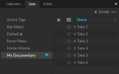
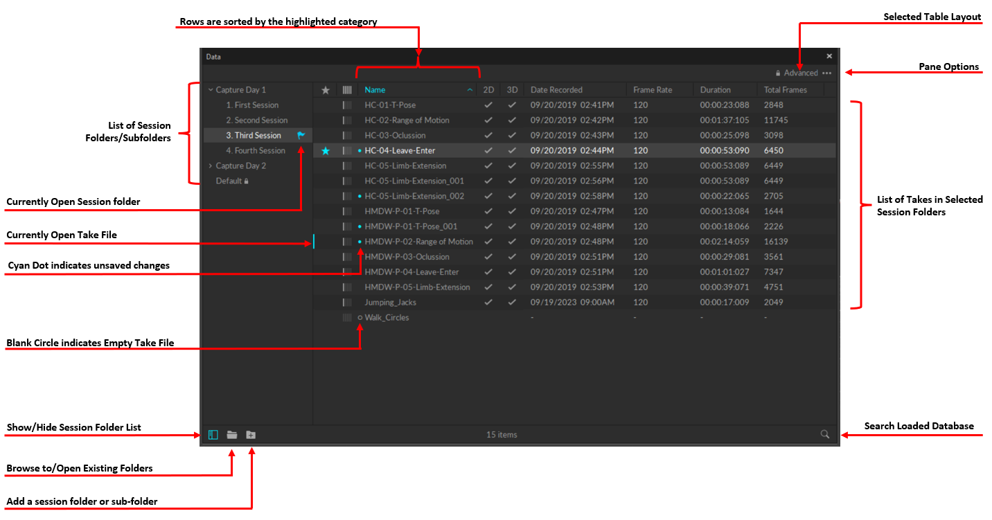
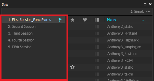
Each capture recording will be saved in a **Take** (TAK) file and related *Take* files can be organized in **session folders**. Start your capture by first creating a new *Session* folder. Create a new folder in the desired directory of the host computer and load the folder onto the [Data pane](/motive-ui-panes/data-pane) by either clicking on the [![IconAdd.png](https://v30.wiki.optitrack.com/images/9/95/IconAdd.png)](https://v30.wiki.optitrack.com/index.php?title=File:IconAdd.png) icon OR just by drag-and-dropping them onto the data management pane. If no session folder is loaded, all of the recordings will be saved onto the default folder located in the user documents directory (Documents\OptiTrack\Default). All of the newly recorded *Takes* will be saved within the currently selected session folder which will be marked with the [![DataManagementPane Flag 111.png](https://v30.wiki.optitrack.com/images/f/f4/DataManagementPane_Flag_111.png)](https://v30.wiki.optitrack.com/index.php?title=File:DataManagementPane_Flag_111.png) symbol.

**See Also:** [Motive Basics](/motive/motive-basics) page.

![Session folders loaded in the Data Management pane](/files/WhAQywm2JVSqJanH9hSU) ![An example session folder in Windows File Explorer.](/files/QZphHRBWAfywBNk01QZs)

**Motive Profiles**

Motive's software configurations are saved to *Motive Profiles* (\*.motive extension). All of the application-related settings can be saved into the Motive profiles, and you can export and import these files and easily maintain the same software configurations.

### Marker Up

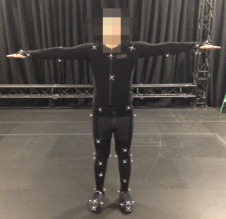
Place the retro-reflective markers onto subjects (Rigid Body or Skeleton) that you wish to track. Double-check that the markers are attached securely. For skeleton tracking, open the [Builder pane](/motive-ui-panes/builder-pane), go to skeleton creation options, and choose a marker set you wish to use. Follow the skeleton avatar diagram for placing the markers. If you are using a mocap suit, make sure that the suit fits as tightly as possible. Motive derives the position of each body segment from related markers that you place on the suit. Accordingly, it is important to prevent the shifting of markers as much as possible. Sample marker placements are shown below.

**See Also:** [Markers](/motive/markers) page for marker types, or [Rigid Body Tracking](/motive/rigid-body-tracking) and [Skeleton Tracking](/motive/skeleton-tracking) page for placement directions.

![Retroreflective markers placed on a quadrocopter](/files/sMBCTauxBeama8hqQn8n) ![The corresponding Rigid Body defined in Motive](/files/kVzwMXMEulPQrvgoOYwG) ![Markers placed for a subject.](/files/JMAIgq28WpiS2G5eV0nJ) ![Markers placements shown for Baseline (41) skeleton shown in the Builder pane.](/files/uv9QzwObmJ3D0leRFNTm)

### Define Skeletons and Rigid Bodies

{% hint style="info" %}
**Tip:** For creating trackable assets, click the *Layout → Create* menu item to access the model creation layout.
{% endhint %}

**Create Rigid Body**

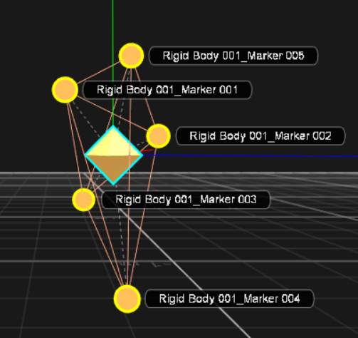
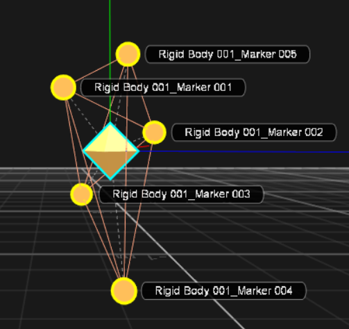
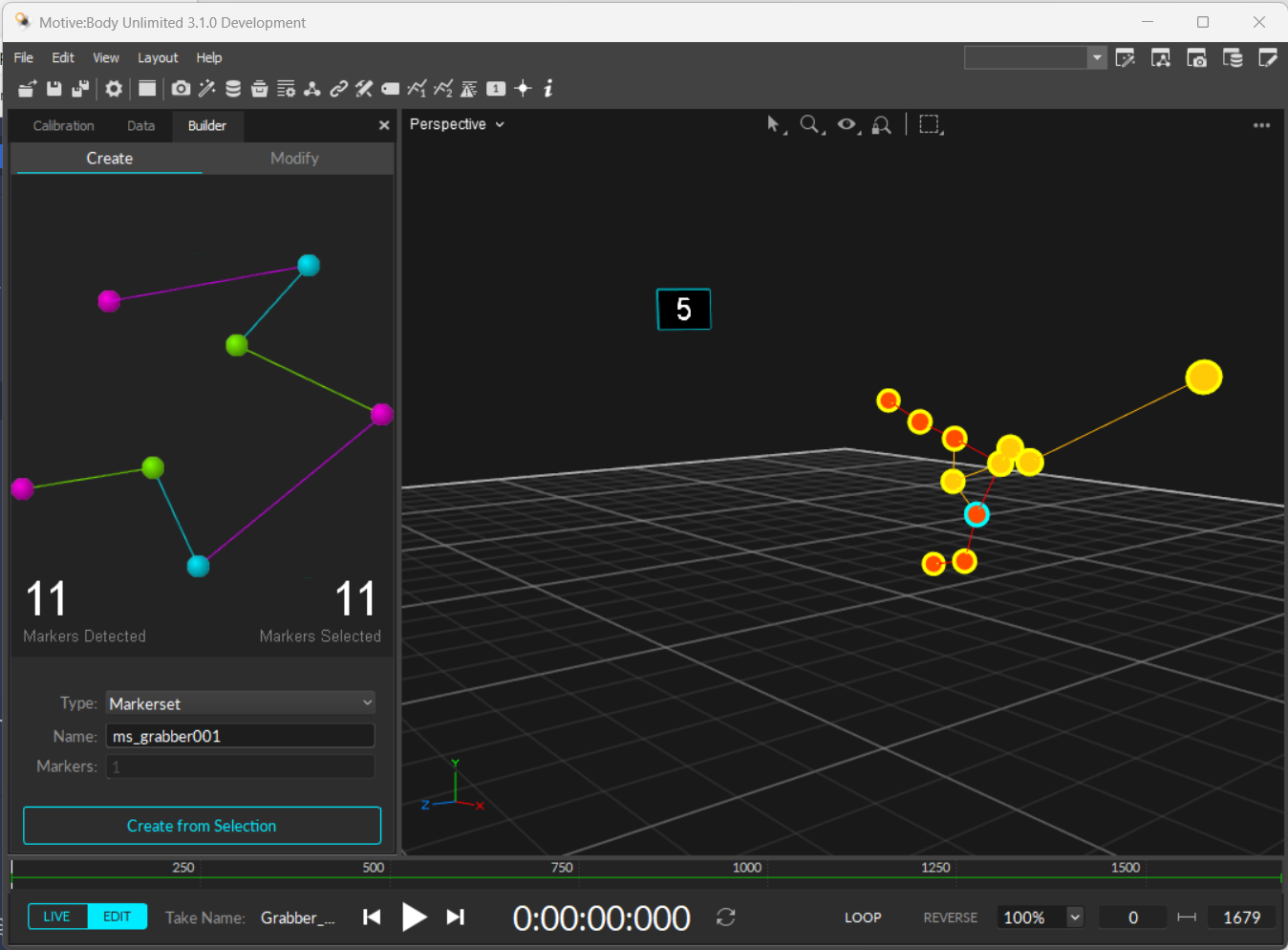
To define a Rigid Body, simply select three or more markers in the Perspective View, right-click, and select *Rigid Body → Create Rigid Body* From Selected. You can also utilize CTRL+T hotkey for creating Rigid Body assets. You can also use the [Builder pane](/motive-ui-panes/builder-pane) to define the Rigid Body.

![](/files/zggoqHrqvSfNjax4kgpC)

**Create Skeleton**

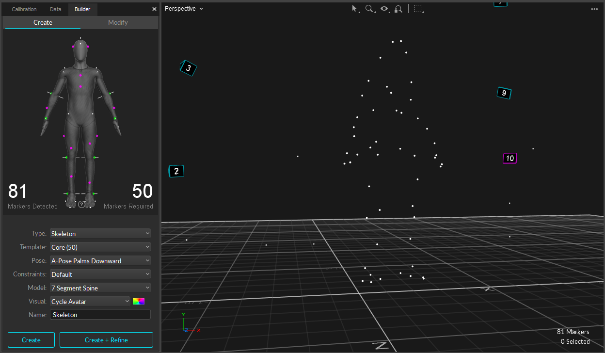
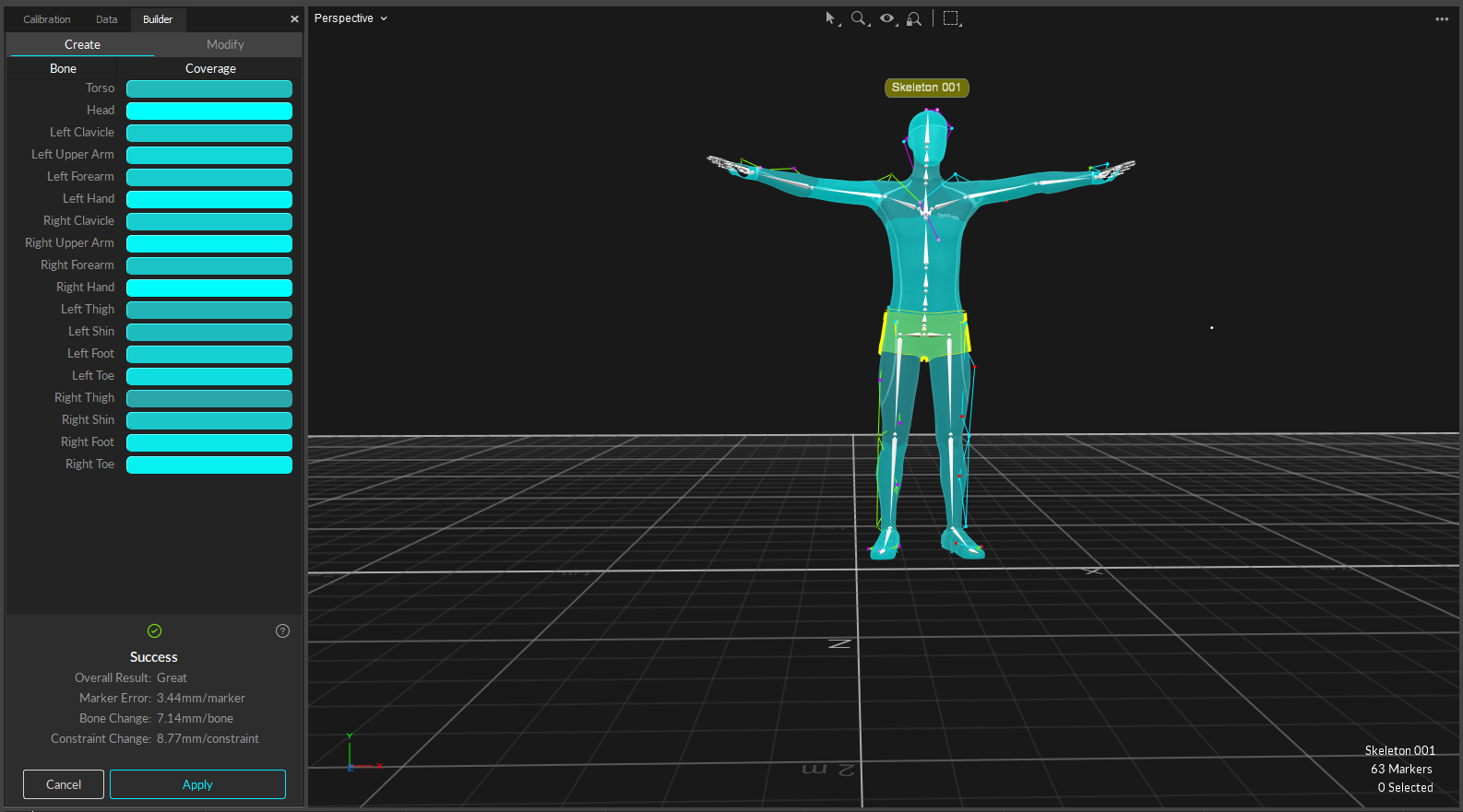
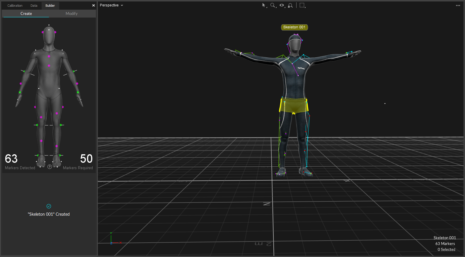
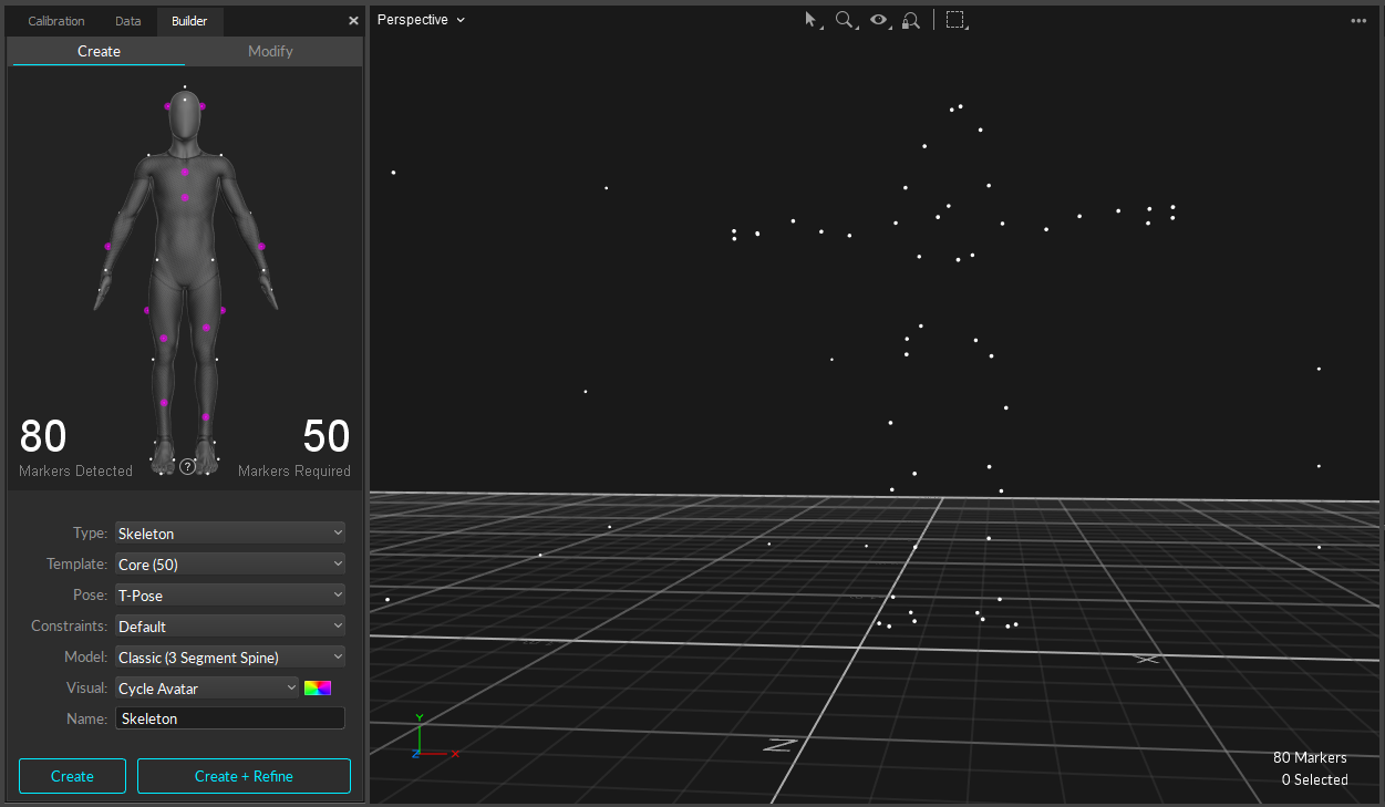
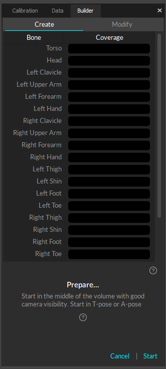
To define a skeleton, have the actor enter the volume with markers attached at appropriate locations. Open the [Builder pane](/motive-ui-panes/builder-pane) and select *Skeleton* and *Create*. Under the marker set section, select a marker set you wish to use, and a corresponding model with desired marker locations will be displayed. After verifying that the marker locations on the actor correspond to those in the Builder pane, instruct the actor to strike the [calibration pose](/motive/skeleton-tracking). Most common calibration pose used is the T-pose. The T-pose requires a proper standing posture with back straight and head looking directly forward. Then, both arms are stretched to sides, forming a “T” shape. While in T-pose, select all of the markers within the desired skeleton in the 3D view and click *Create* button in the [Builder pane](/motive-ui-panes/builder-pane). In some cases, you may not need to select the markers if only the desired actor is in view.

**See Also:** [Rigid Body Tracking](/motive/rigid-body-tracking) page and [Skeleton Tracking](/motive/skeleton-tracking) page.

![Using Builder pane to define a skeleton](/files/N5gv3tNDkG7XYctIeihN)

### Record Data

{% hint style="info" %}
**Tip:** For recording capture, access the *Layout → Capture* menu item, or the to access the capture layout
{% endhint %}

Once the volume is calibrated and skeletons are defined, now you are ready to capture. In the [Control Deck](/motive-ui-panes/control-deck) at the bottom, press the dimmed red record button or simply press the spacebar when in the [Live mode](/motive/motive-basics) to begin capturing. This button will illuminate in bright red to indicate recording is in progress. You can stop recording by clicking the record button again, and a corresponding capture file (TAK extension), also known as capture *Take*, will be saved within the current session folder. Once a *Take* has been saved, you can playback captures, reconstruct, edit, and export your data in a variety of formats for additional analysis or use with most 3D software.

When tracking skeletons, it is beneficial to start and end the capture with a T-pose. This allows you to recreate the skeleton in post-processing when needed.

**See Also:** [Data Recording](/motive/data-recording) page.

## Post-Capture

### Data Editing

After capturing a *Take*. Recorded 3D data and its trajectories can be post-processed using the [Data Editing](/motive/data-editing) tools, which can be found in the [Edit Tools pane](/motive-ui-panes/edit-tools-pane). Data editing tools provide post-processing features such as deleting unreliable trajectories, smoothing select trajectories, and interpolating missing (occluded) marker positions. Post-editing the 3D data can improve the quality of tracking data.

{% hint style="info" %}
**Tip:** For data editing, access the *Layout → Edit* menu item, or the to access the capture layout
{% endhint %}

**General Editing Steps**

1. Skim through the overall frames in a Take to get an idea of which frames and markers need to be cleaned up.
2. Refer to the [Labels pane](/motive-ui-panes/labels-pane) and inspect gap percentages in each marker.
3. Select a marker that is often occluded or misplaced.
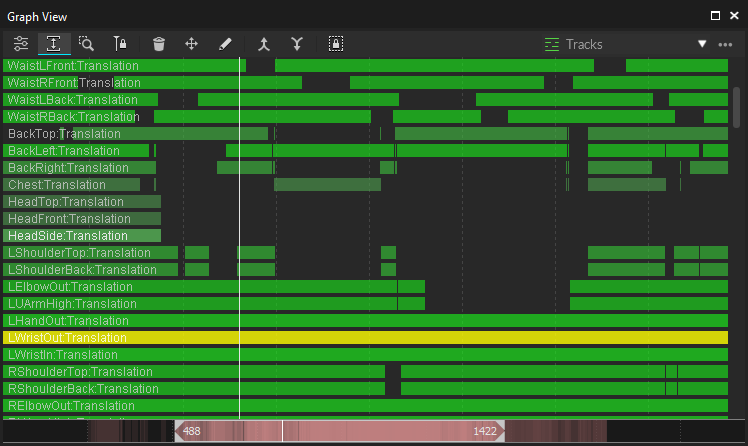
4. Look through the frames in the [Graph pane](/motive-ui-panes/graph-view-pane), and inspect the gaps in the trajectory.
5. For each gap in frames, look for an unlabeled marker at the expected location near the solved marker position. Re-assign the proper marker label if the unlabeled marker exists.
6. Use Trim Tails feature to trim both ends of the trajectory in each gap. It trims off a few frames adjacent to the gap where tracking errors might exist. This prepares occluded trajectories for Gap Filling.
7. Find the gaps to be filled, and use the Fill Gaps feature to model the estimated trajectories for occluded markers.
8. Re-Solve assets to update the solve from the edited marker data

### Marker Labeling

Markers detected in the camera views get trajectorized into 3D coordinates. The reconstructed markers need to be labeled for Motive to distinguish different trajecectories within a capture. Trajectories of annotated reconstructions can be exported individually or used (solved altogether) to track the movements of the target subjects. Markers associated with Rigid Bodies and Skeletons are labeled automatically through the auto-labeling process. Note that Rigid Body and Skeleton markers can be auto-labeled both during Live mode (before capture) and Edit mode (after capture). Individual markers can also be labeled, but each marker needs to be manually labeled in post-processing using [assets](/motive/assets) and the [Labeling pane](/motive-ui-panes/labels-pane). These manual [Labeling](/motive/labeling) tools can also be used to correct any labeling errors. Read through the [Labeling](/motive/labeling) page for more details in assigning and editing marker labels.

* **Auto-label:** Automatically label sets of Rigid Body markers and skeleton markers using the corresponding asset definitions.
* **Manual Label:** Labeling individual markers manually using the [Labeling](/motive/labeling), assigning labels defined in the Marker Set, Rigid Body, or Skeleton assets.

**See Also:** [Labeling](/motive/labeling) page.

![Unlabeled passive markers displayed in white. Color settings can be adjusted from the Application Settings.](/files/YQncZkXEg7ERLnnUBgiU) ![Labeled skeleton markers displayed in assigned color. Marker colors and sticks can be modified using Constraints pane.](/files/t8T0QzPUioWgdtTSV0Di) ![Labeled Rigid Body markers displayed in assigned color. Rigid Body colors can be adjusted from the Rigid Body properties.](/files/BjVTMnDZ6xihcge46Mjk)

{% hint style="info" %}
**Changing Marker Labels and Colors**

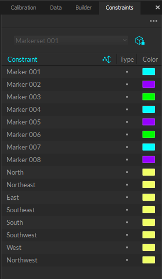
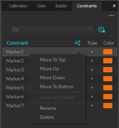
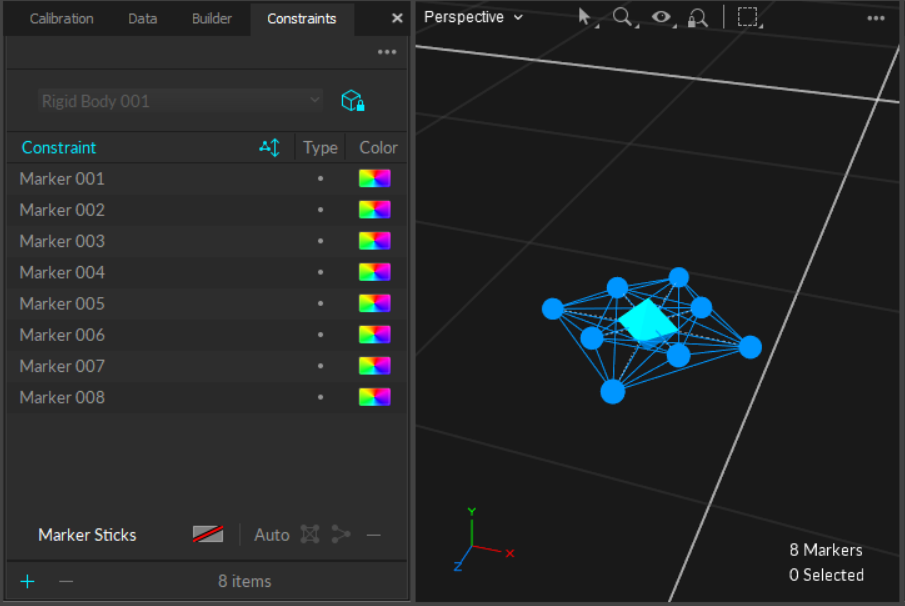
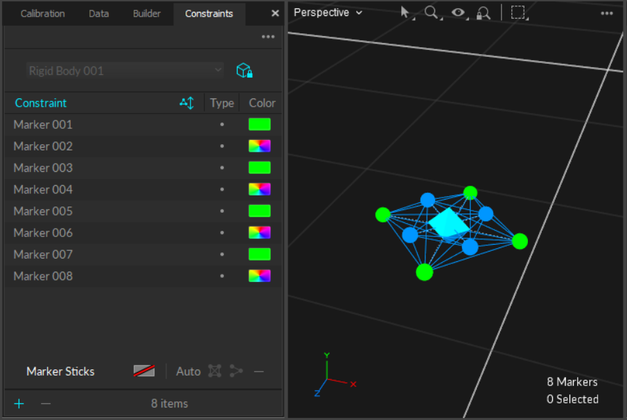
When needed, you can use the [Constraints pane](/motive-ui-panes/constraints-pane) to adjust marker labels for both Rigid Body and Skeleton markers. You can also adjust markers sticks and marker colors as needed.
{% endhint %}

## Data Export

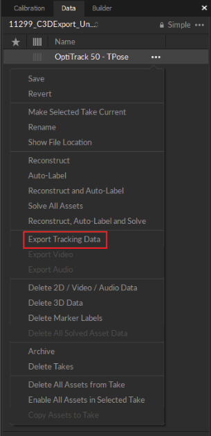
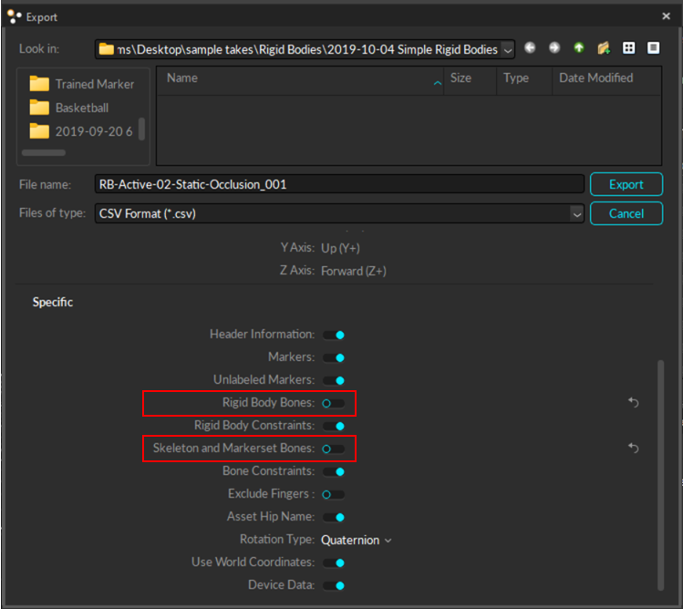
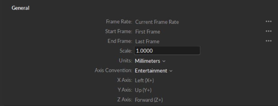
Motive exports reconstructed 3D tracking data in various file formats, and exported files can be imported into other pipelines to further utilize capture data. Supported formats include CSV and C3D for **Motive: Tracker**, and additionally, FBX, BVH, and TRC for **Motive: Body**. To export tracking data, select a Take to export and open the export dialog window, which can be accessed from *File → Export Tracking Data* or *right-click on a Take → Export Tracking data* from the [Data pane](/motive-ui-panes/data-pane). Multiple *Takes* can be selected and exported from Motive or by using the [Motive Batch Processor](/motive/motive-batch-processor). From the export dialog window the frame rate, measurement scale, and frame range of exported data can be configured. Frame ranges can also be specified by selecting a frame range in the [Graph View pane](/motive-ui-panes/graph-view-pane) before exporting a file. In the export dialog window, corresponding export options are available for each file format.

**See Also:** [Data Export](/motive/data-export) page.

![Tracking data export dialogue window in Motive. CSV export is selected and corresponding export options are listed. Click image to enlarge.](/files/FLZ1yfdznelB6MPQ19Di)

## Data Streaming

Motive offers multiple options to stream tracking data onto external applications in real-time. Tracking data can be streamed in both Live mode and Edit mode. Streaming plugins are available for Autodesk Motion Builder, Visual3D, The MotionMonitor, Unreal Engine 4, 3ds Max, Maya (VCS), and VRPN, and they can be downloaded from the [OptiTrack website](http://optitrack.com/downloads/plugins.html). For other streaming options, the NatNet SDK enables users to build custom client and server applications to stream capture data. Common motion capture applications rely on real-time tracking, and the OptiTrack system is designed to deliver data at an extremely low latency even when streaming to third-party pipelines. Detailed instructions on specific [streaming protocols](/quick-start-guides/quick-start-guide-getting-started) are included in the PDF documentation that ships with the respective plugins or SDK's.

**See Also:** [Data Streaming](/motive/data-streaming) page

![Data Streaming in Motive allows you to stream capture data into other applications.](/files/xiXjJqjVpR0S17ynGc9n)


# Quick Start Guide: Prime Color Camera Setup

Optimize a Prime Color Camera system with recommended settings for best performance.

This quick start guide applies to Prime Color and Prime Color FS setups.&#x20;

Please see our full [Prime Color Camera](/movement-sciences/prime-color-camera-setup) chapter for more in-depth information on each topic.

{% hint style="info" %}
If you experience latency or camera drops, you may need to increase the specifications on certain components, especially if your system includes a large number of Prime Color cameras. Please reach out to our [Support ](https://optitrack.com/support/)team, if you continue experiencing these issues after upgrading to the hardware specifications and setup recommendations below.&#x20;
{% endhint %}

## 1-2 Color Camera Setup Hardware Requirements

| PC                                                                                     | Network Devices                       |
| -------------------------------------------------------------------------------------- | ------------------------------------- |
| Windows 10 or 11 Professional (64 Bit)                                                 | Designated 1Gbps NIC w/drivers        |
| CPU: Intel i9 or better 3.5GHz+                                                        | Network switch with 1Gbps uplink port |
| RAM: 16GB+ of memory                                                                   |                                       |
| GPU: GTX 1050 or better with latest drivers and supports OpenGL version 4.0 or higher. |                                       |
| M.2 SSD                                                                                |                                       |

## 3+ Color Camera Setup Hardware Requirements

| PC                                                                                     | Network Devices                         |
| -------------------------------------------------------------------------------------- | --------------------------------------- |
| Windows 10 or 11 Professional (64 Bit)                                                 | Designated 10Gbps+ NIC w/drivers        |
| CPU: Intel i9 or better 3.5GHz+                                                        | Network switch with 10Gbps+ uplink port |
| RAM: 32GB+ of memory                                                                   |                                         |
| GPU: RTX 2070 or better with latest drivers and supports OpenGL version 4.0 or higher. |                                         |
| M.2 SSD                                                                                |                                         |

## Quick Start Hardware Setup

### Cabling

#### **Power**

Each Prime Color camera must be uplinked and powered through a standard PoE connection that can provide at least 15.4 watts to each port simultaneously.

{% hint style="warning" %}
Please note that if your aggregation switch is PoE, you can plug your Prime Color Cameras **directly** into the aggregation switch. PoE injectors are **optional** and are only required if your aggregation switch is not PoE.
{% endhint %}

{% tabs %}
{% tab title="One or Two Color Cameras" %}
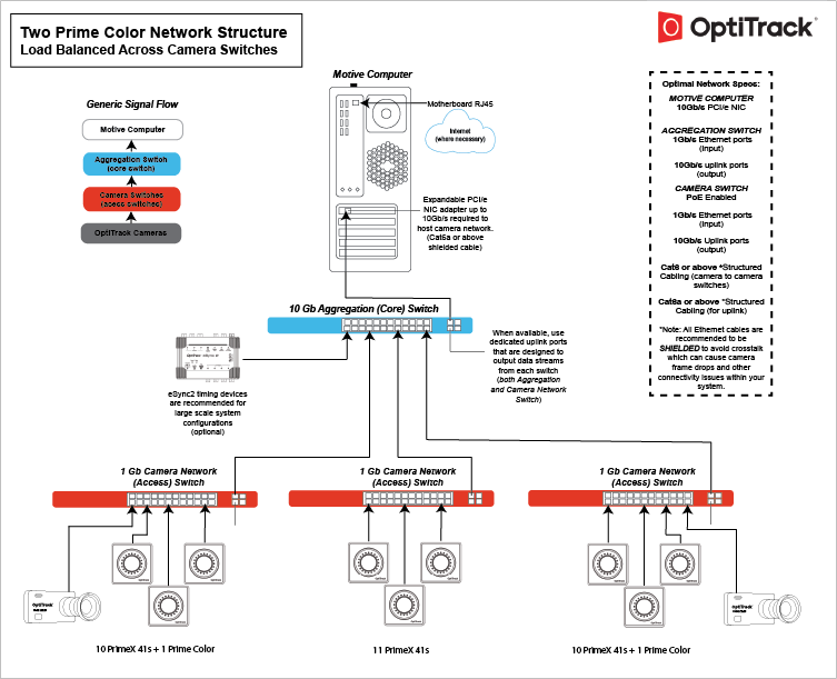
Prime Color cameras connect to the camera system just like other Prime series camera models. Simply plug the camera onto a PoE switch that has enough available bandwidth and it will be powered and synchronized along with other tracking cameras. When you have two color cameras, they will need to be distributed evenly onto different PoE switches so that the data load is balanced.

<figure><img src="/files/hWyg9oK7IOXgVTm7VvHu" alt=""><figcaption></figcaption></figure>

{% hint style="info" %}
For 1-2 Prime Color Cameras we recommend using a 1Gbps network switch with 1Gbps uplink port and a 1Gpbs NIC or higher. For 3+ Prime Color Cameras it is required to use network switches with a 10Gbps uplink port in conjunction with a 10Gbps designated NIC and their appropriate drivers.&#x20;

NIC drivers may need to be installed via disc or downloaded from the manufacture's support website. If you're unsure of where to find these drivers or how to install them, please reach out to our [Support ](https://optitrack.com/support/)team.
{% endhint %}

#### Load Balancing and Bit Rate&#x20;

Higher bit rates send more data across the network, which needs to be accounted for in load balancing the network. For example, 3 PrimeX Color cameras running at 100MB/s can easily surpass 1 Gb of data throughput, potentially resulting in dropped frames if all are connected to the same switch.

When connecting PrimeX Color cameras to a camera network switch rather than directly to the aggregate (core) switch, we recommend connecting no more than 1 camera per switch, at a maximum bit rate of 30-50 Mb/s, for optimal quality.

#### SFP Uplink ports

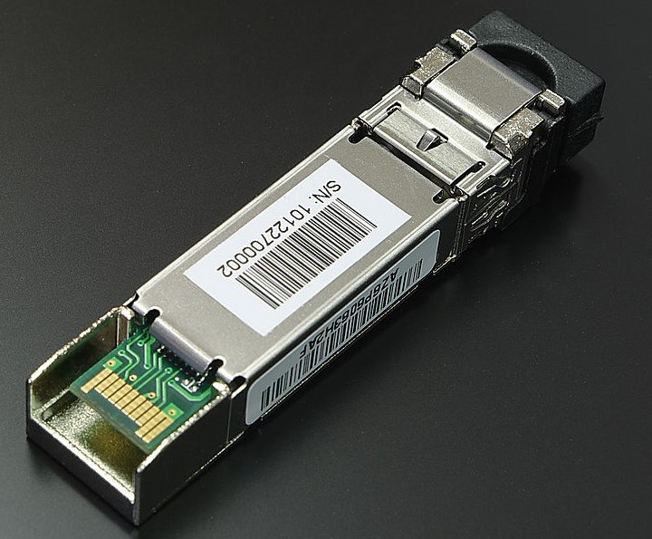
The uplink ports on the camera network switches must be able to connect to the aggregate or core switch at 10 Gb when a PrimeX Color camera is connected. This may require an SFP Injector in an SFP uplink port to allow the port to transmit data at 10 Gb.
{% endtab %}

{% tab title="Multiple Color Cameras" %}
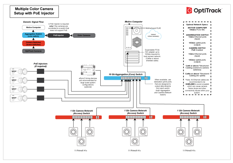
When using multiple Prime Color cameras, we recommend connecting the color cameras directly into the 10-gigabit aggregation (uplink) switch. This configuration allows the data to travel directly through the uplink switch to the host computer through the 10-gigabit network interface. This also separates the color cameras from the tracking cameras.&#x20;

To connect all the PrimeX Color cameras to the same switch, the switch must be able to uplink 10Gb/s with at least 1Gb/s of bandwidth per access port.

{% hint style="danger" %}
A PoE injector is required if the uplink switch does not provide PoE.&#x20;
{% endhint %}

<figure><img src="/files/0jprSMw4wZQezK63SbNs" alt=""><figcaption></figcaption></figure>
{% endtab %}

{% tab title="Color Cameras Only" %}
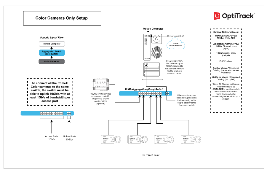
To connect all the PrimeX Color cameras to the same switch, the switch must be able to uplink 10Gb/s with at least 1Gb/s of bandwidth per access port.

<figure><img src="/files/XQRezPLpKDyuismBAwIP" alt=""><figcaption></figcaption></figure>
{% endtab %}
{% endtabs %}

### Ethernet Cable Requirements

#### **Cable Type**

There are multiple categories for Ethernet cables, and each has different specifications for maximum data transmission rate and cable length. For an Ethernet based system, Cat6 or above Gigabit Ethernet cables should be used. 10 Gigabit Ethernet cables – Cat6a or above — are recommended in conjunction with a 10 Gigabit uplink switch for the connection between the uplink switch and the host PC in order to accommodate for high data traffic.

{% hint style="info" %}
**Note**

10Gb uplink switches, NICs, and cables are recommended for large camera counts or high data cameras like the Prime Color cameras. Typically 1Gb switches, NICs, and cables should be enough to accommodate smaller and moderately sized systems. If you're unsure of whether or not you need more than 1Gb, please contact one of our Sales Engineers [here](https://optitrack.com/contact/) or see our [Cabling and Load Balancing](/hardware/cabling-and-wiring/cabling-and-load-balancing) page for more information.
{% endhint %}

#### **Electromagnetic Shielding**

We recommend using only cables that have electromagnetic interference shielding. If unshielded cables are used, cables in close proximity to each other have the potential to create data transfer interference and cause cameras to stall in Motive.

{% hint style="danger" %}
Unshielded cables do not protect the cameras from Electrostatic Discharge (ESD), which can damage the camera. Do not use unshielded cables in environments where ESD exposure is a risk.&#x20;
{% endhint %}

## Windows Setup

### Debloat Windows

Remove all "bloatware" from the Motive PC to optimize the system and to ensure unnecessary background processes are not running. Background processes take valuable CPU resources from Motive and can cause frame drops while the camera system is running.&#x20;

There are many external resources to guide you in removing unused apps and halting unnecessary background processes. Those steps will not be covered within the scope of this page.&#x20;

### Firewall and Antivirus Settings

As a general rule for all OptiTrack camera systems, best practice is to disable Windows firewalls and disable or remove any Antivirus software. Both can cause frame drops while running your camera system.&#x20;

{% hint style="warning" %}
These optimizations involve disabling various Windows security features. It is crucial that the PC is isolated from the internet or other potential sources of malware.
{% endhint %}

#### Windows 11 Local Group Policy Editor

Many of the recommended optimizations are completed using Window’s *Local Group Policy Editor*. To open this program:

1. From the Windows search bar, type *CMD*.
2. Run *Command Prompt* as administrator.&#x20;
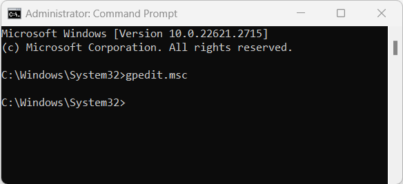
3. At the command line, type *gpedit.msc* and press enter.
4. This will open the *Local Group Policy Editor* window.&#x20;

<figure><img src="/files/GsOQshGcdyqehK0VPIV8" alt="" width="438"><figcaption><p>Windows Command Prompt in Administrator mode.</p></figcaption></figure>

#### Disable Firewall

Set a Local Group Policy to disable Private, Public, and Domain firewalls.&#x20;

{% hint style="warning" %}
Once these policies are implemented, the firewall cannot be re-enabled by any other means.&#x20;
{% endhint %}

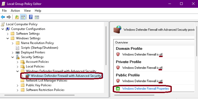
<figure><img src="/files/Q69FwYFR4g8fE415n6G2" alt=""><figcaption><p>Local Group Policy Editor:  Windows Defender Firewall and Advanced Security Overview.</p></figcaption></figure>

1. Open Window’s [Local Group Policy Editor](#local-group-policy-editor).
2. Navigate to *Computer Configuration -> Windows Settings -> Security Settings -> Windows Defender Firewall with Advanced Security.*
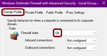
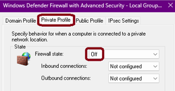
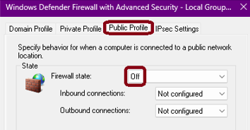
3. The Overview panel shows the current status of the firewall. Click *Windows Defender Firewall Properties* to change the state of the *Domain, Private,* and *Public* profiles to *Off* then click OK.

<div><figure><img src="/files/wIZLrswWVMm91rY7Ar49" alt=""><figcaption><p>Domain Profile settings.</p></figcaption></figure> <figure><img src="/files/p0Gn9iut5MObQic1dJpf" alt=""><figcaption><p>Private Profile settings.</p></figcaption></figure> <figure><img src="/files/ybTGPyVRsxPnhV4ELd87" alt=""><figcaption><p>Public Profile settings.</p></figcaption></figure></div>

#### Disable Antivirus

Set a Local Group Policy to disable Microsoft Defender Antivirus.&#x20;

{% hint style="warning" %}
Once this policy is implemented, the Windows Defender Antivirus cannot be re-enabled in Virus & Threat Protection.
{% endhint %}

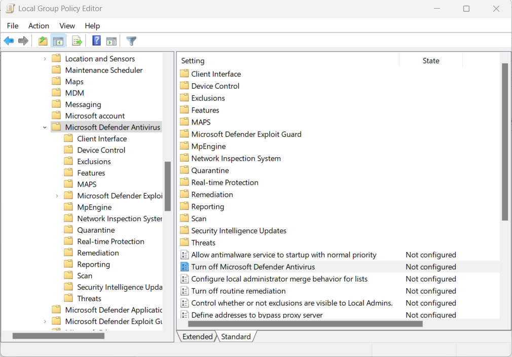
<figure><img src="/files/1hLkfuepFN4VoLUXsGwD" alt="" width="563"><figcaption><p>Local Group Policy Editor:  Microsoft Defender Antivirus settings.</p></figcaption></figure>

1. Open Window’s [Local Group Policy Editor](#local-group-policy-editor).
2. Navigate to *Computer Configuration -> Administrative Templates -> Windows Components -> Microsoft Defender Antivirus*.
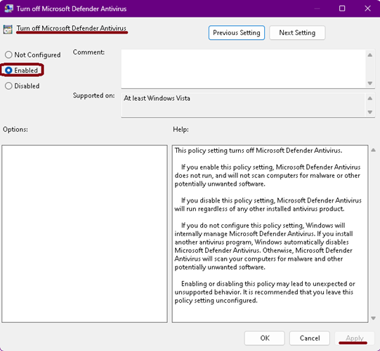
3. Double-click *Turn Off Microsoft Defender Antivirus*.
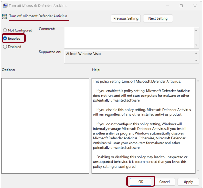
4. Select *Enabled* and click OK.

<figure><img src="/files/DOqMJlwHIak5q9iGibdy" alt="" width="406"><figcaption><p>Turning off Microsoft Defender Antivirus.</p></figcaption></figure>

#### Disable Anti-malware Real-time Protection

1. Open Window’s [Local Group Policy Editor](#local-group-policy-editor).
2. Navigate to:  *Computer Configuration -> Administrative Templates -> Windows Components -> Microsoft Defender Antivirus -> Real-time Protection.*
3. Double-click *Turn off real-time Protection*.
4. Set the policy to Enabled and click OK.

<figure><img src="/files/B6Ggews7nT9D0XumR6BA" alt="" width="506"><figcaption><p>Turning off Microsoft Defender Real-time Protection</p></figcaption></figure>

### Priority&#x20;

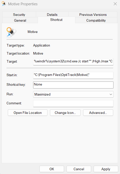
Customize the Motive desktop shortcut to launch the program with high priority.

<figure><img src="/files/FlNdCy2YZQJcp8fsoFcL" alt="" width="359"><figcaption><p>Motive shortcut properties window.</p></figcaption></figure>

* On the desktop, right-click the Motive shortcut and select *Properties*.
* Select the *Shortcut* tab.
* Copy and paste the text below into the *Target* field:

C:\Windows\System32\cmd.exe /C start "" /high "C:\Program Files\OptiTrack\Motive\Motive.exe"

* Set the *Run* property to *Maximized*.
* Click *OK* to save your changes and close the window.

{% hint style="danger" %}
**Do not set the priority to Realtime.** This can cause Windows to prioritize Motive above input processes such as mouse and keyboard, resulting in a loss of input control.
{% endhint %}

### Processor Affinity (Optional)

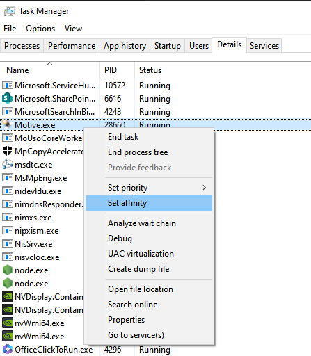
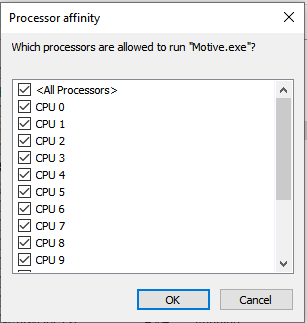
If the system has a CPU with a lower core count, you may need to disable Motive from running on one or two cores. This will help stabilize the overall system and free those cores for other Windows-required processes.&#x20;

* From the Task Manager, navigate to the Details tab and right click on Motive.exe.
* Select Set Affinity.&#x20;
* From this window, uncheck the cores you wish to disable for Motive.exe to run on.&#x20;
* Click OK.

{% hint style="danger" %}
**Do not disable more than 2 cores** to insure Motive still runs smoothly. We recommend starting with one core and disabling a second only if frame drop issues continue.

**Do not disable more cores than cameras.** Motive requires at least one core for each PrimeX Color Camera on the system.&#x20;
{% endhint %}

<div><figure><img src="/files/IhiXdKWVVrhv063OIiqw" alt=""><figcaption></figcaption></figure> <figure><img src="/files/yjGUo82AgxHrfXgORcs2" alt=""><figcaption></figcaption></figure></div>

## Network Setup

### Switch Settings

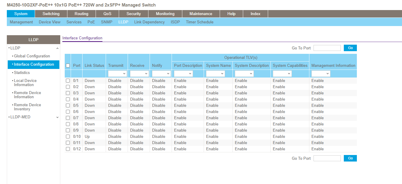
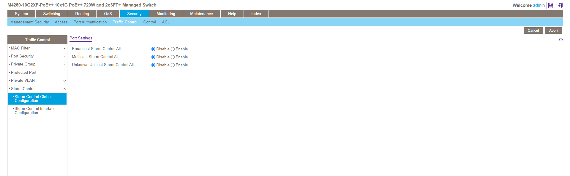
Switches purchased as a component of the OptiTrack system will ship with the proper configuration. If using a switch purchased elsewhere, ensure that any built-in [Storm Control](/hardware/cabling-and-wiring/netgear-prosafe-gsm7228s-disabling-the-broadcast-storm-control) features are disabled.&#x20;

### NIC Settings

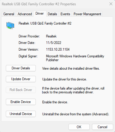
The Network Interface Card (NIC) has two settings to optimize your system and reduce issues when capturing Prime Color Camera video.

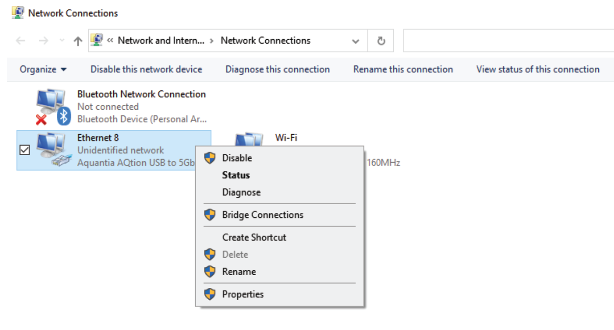
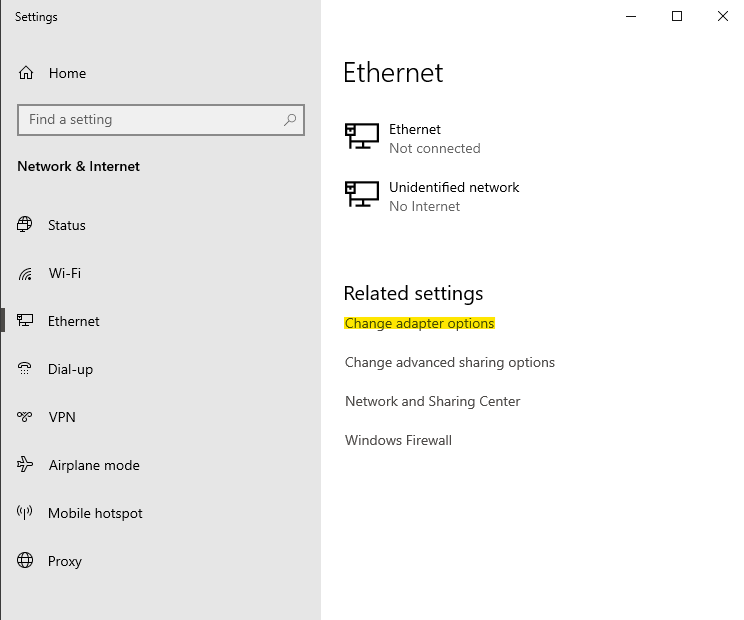
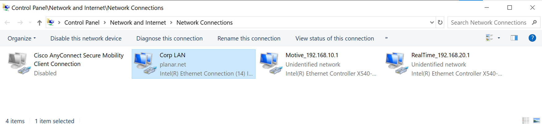
1. To configure the NIC, type *Network* in the Windows search bar to find and open the Control Panel to *View Network Connections.*&#x20;
2. Double-click or right-click the NIC for the camera system and select *Properties*.

<figure><img src="/files/p6GSybnoBbCif0JGMtH7" alt=""><figcaption><p>Network Connections in Windows.</p></figcaption></figure>

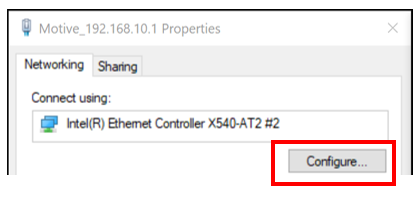
On the Properties window, click the *Configure...* button.&#x20;

<figure><img src="/files/EKeVZZpVYfh7tBRDdgwt" alt=""><figcaption><p>Network Properties: Configure NIC</p></figcaption></figure>

Click the *Advanced* tab to access the NIC Properties.&#x20;

#### Speed & Duplex

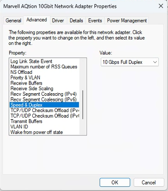
This setting determines the rate of data transmission (speed) and whether the NIC can operate at its full range (full duplex) or if throttling will occur (half duplex).&#x20;

The property should be set to the highest throughput of the NIC. For example, if you have a 10Gbps NIC, select *10Gbps Full Duplex*.&#x20;

<figure><img src="/files/G0H71V7iixmMJwI8cnR3" alt=""><figcaption><p>NIC Properties: Speed &#x26; Duplex recommended setting.</p></figcaption></figure>

#### Interrupt Moderation

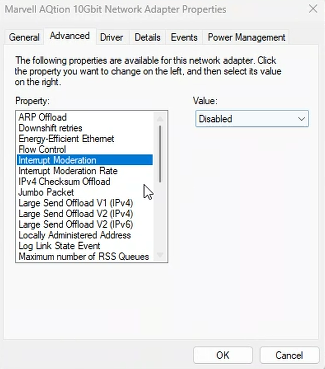
This setting allows the NIC to moderate interrupts. When there is a significant amount of data being transmitted to Motive, Interrupt Moderation can increase the number of interrupts, impacting system performance.&#x20;

This property should be disabled.&#x20;

<figure><img src="/files/97MZL6S5uwQUgTWgTqeW" alt=""><figcaption><p>NIC Properties: Interrupt Moderation recommended setting.</p></figcaption></figure>

#### Restart NIC

To apply changes made to the NIC properties, the NIC must be restarted.&#x20;

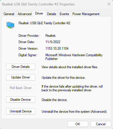
1. Click the *Driver* tab.
2. Click *Disable*, then *Enable* to restart the NIC with the new settings.&#x20;

<div><figure><img src="/files/Uiy8i0Hd3PJepnd3cFwB" alt=""><figcaption><p>NIC Properties: Driver Tab - Disable Device</p></figcaption></figure> <figure><img src="/files/4QEMLQ3Howm9jM2AGnlG" alt=""><figcaption><p>NIC Properties: Driver Tab - Enable Device</p></figcaption></figure></div>

{% hint style="danger" %}
Rebooting the NIC will take the camera system down for a few minutes. This is normal and once the NIC is rebooted the system should work as expected.&#x20;
{% endhint %}

#### NIC Adapters (Laptop)

Although not recommended, you can use a laptop PC to run a Prime Color Camera system. The laptop will require an external network adapter to connect to the camera network. The settings noted above typically do not apply to these types of adapters.

{% hint style="info" %}
Use a Thunderbolt port adapter with a corresponding Thunderbolt port on your laptop rather than standard USB-C adapters/ports.&#x20;
{% endhint %}

## Motive Setup

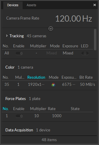
Prime color cameras are displayed as a separate category under the Devices pane. You can customize the column view and configure select camera settings directly from this pane. Please see the [Devices Pane ](/motive-ui-panes/devices-pane)page for more information.&#x20;

<figure><img src="/files/RvCjcgUjl4KH4CXnCUZL" alt=""><figcaption><p>Color Camera in the Devices Pane.</p></figcaption></figure>

### Prime Color Settings

Select the camera to display its properties in the [Properties pane](/motive-ui-panes/properties-pane/properties-pane-camera). The following settings are unique to Color Cameras.&#x20;

{% hint style="info" %}
We recommend closing the [Cameras View](/motive-ui-panes/viewport#cameras-view) during recording to further stabilize Motive, minimizing lag and reducing frame drops.
{% endhint %}

#### Resolution

This property sets the resolution of the images captured by the selected camera.

You may need to reduce the maximum frame rate to accommodate the additional data produced by recording at higher resolutions. The table below shows the maximum allowed frame rates for each respective resolution setting.

| Resolution                    | Max Frame Rate |
| ----------------------------- | -------------- |
| 960 x 540 (540p)              | 500 FPS        |
| 1280 x 720 (720p)             | 360 FPS        |
| 1920 x 1080 (1080p) *Default* | 250 FPS        |

#### Bit Rate

This setting determines the selected color camera's output transmission rate, and is only applicable when the [Compression mode](/motive-ui-panes/properties-pane/properties-pane-camera#compression-mode) for the camera is set to [Constant Bit Rate](/motive-ui-panes/properties-pane/properties-pane-camera#bit-rate) (the default value) in the Camera properties.&#x20;

The maximum data transmission speed that a Prime color camera can output is 100 megabytes per second (MB/s). At this setting, the camera will capture the best quality image, however, it could overload the network if there isn't enough bandwidth to handle the transmitted data. We recommend setting the bit rate in the 30-50 Mb/s range for optimal quality.&#x20;

**Load Balancing and Bit Rate:** Higher bit rates send more data across the network, which needs to be accounted for in load balancing the network. For example, 3 PrimeX Color cameras running at 100MB/s can easily surpass 1 Gb of data throughput, potentially resulting in dropped frames if all are connected to the same switch.

{% hint style="info" %}
Since the bit-rate controls the rate of data each color camera outputs, this is one of the most important settings to adjust when configuring the system.&#x20;

When a system is experiencing 2D frame drops, one of the following system requirements is not being met:&#x20;

* Network bandwidth
* CPU processing speed
* Insufficient number of available or utilized CPU cores
* RAM/disk memory

Decreasing the bit-rate in such cases may slow the data transmission speed of the color camera enough to resolve the problem.
{% endhint %}

Read more about compression mode and bit rate settings on the page [Properties Pane: Camera](/motive-ui-panes/properties-pane/properties-pane-camera).&#x20;

#### Gamma

Gamma correction is a non-linear amplification of the output image. The gamma setting adjusts the brightness of dark pixels, mid-tone pixels, and bright pixels differently, affecting both brightness and contrast of the image. Depending on the capture environment, especially with a dark background, you may need to adjust the gamma setting to get best quality images.

### Color Camera Presets

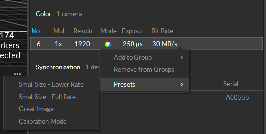
Presets for Color Cameras use standard settings to optimize for different outcomes based on file size and image quality.  Calibration mode sets the appropriate video mode for the camera type in addition to other setting changes.&#x20;

<figure><img src="/files/BKHS8ZEPSQscQWh7xcjX" alt=""><figcaption><p>Color Camera preset options.</p></figcaption></figure>

{% hint style="info" %}
The optimal [Bit Rate](#bit-rate) for each preset is calculated based on the master camera frame rate when the preset is selected. Lower bit rates result in smaller file sizes. Higher bit rates produce higher quality captures and result in larger file sizes.
{% endhint %}

* **Small Size - Lower Rate**
  * Video Mode:  Color Video
  * Rate Multiplier:  1/4 (or closest possible)
  * Exposure:  20000 (or max)
  * Bit Rate:  \[calculated]
* **Small Size - Full Rate**
  * Video Mode:  Color Video
  * Rate Multiplier:  x1
  * Exposure:  20000 (or max)
  * Bit Rate:  \[calculated]
* **Great Image**
  * Video Mode:  Color Video
  * Rate Multiplier:  x1
  * Exposure:  20000 (or max)
  * Bit Rate:  \[calculated]
* **Calibration Mode**
  * Video Mode: &#x20;
    * FS Series:  Object Mode
    * Non-FS Series: Color Object Mode
  * Rate Multiplier:  x1
  * Exposure:  250
  * Bit Rate:  N/A


# Quick Start Guide: Precision Capture

With an optimized system setup, motion capture systems are capable of obtaining extremely accurate tracking data from a small to medium sized capture volume. This quick start guide includes general tips and suggestions on precision capture system setups and important cautions to keep in mind. This page also covers some of the precision verification methods in Motive. For more general instructions, please refer to the [Quick Start Guide: Getting Started](/quick-start-guides/quick-start-guide-getting-started) or corresponding workflow pages.

## Residual Value

Before going into details on precision tracking with an OptiTrack system, let's start with a brief explanation of the *residual* value, which is the key [reconstruction](/motive/reconstruction-and-2d-mode) output for monitoring the system precision. The [residual](/motive/reconstruction-and-2d-mode) value is an average offset distance, in mm, between the converging rays when reconstructing a marker; hence indicating preciseness of the reconstruction. A smaller residual value means that the tracked rays converge more precisely and achieve more accurate 3D reconstruction. A well-tracked marker will have a sub-millimeter average residual value. In Motive, the tolerable residual distance is defined from the [Reconstruction Settings](/motive/reconstruction-and-2d-mode) under the Application Settings panel.

When one or more markers are selected in the Live mode or from the [2D Mode](/motive/reconstruction-and-2d-mode) of capture data, the corresponding mean residual value is displayed over the [Status Panel](/motive-ui-panes/status-panel) located at the bottom-right corner of Motive.

![Multiple tracked rays contributing to a 3D reconstruction. Click image to enlarge.](/files/L8Qq3uHP94DeAORH2cJx) ![Residual offsets at the converging point of the multiple rays.](/files/crUydgdEaDIPJEeaAwdw)

## Capture Volume

First of all, optimize the capture volume for the most precise and accurate tracking results. Avoid a populated area when setting up the system and recording a capture. Clear any obstacles or trip hazards around the capture volume. Physical impacts on the setup will distort the calibration quality, and it could be critical especially when tracking at a sub-millimeter accuracy. Lastly, for best results, routinely recalibrate the capture volume.

### Infrared Black Background Objects

Motion capture cameras detect reflected infrared light. Thus, having other reflective objects in the volume will alter the results negatively, which could be critical especially for precise tracking applications. If possible, have background objects that are IR black and non-reflective. Capturing in a dark background provides clear contrast between bright and dark pixels, which could be less distinguishable in a white background.

![The images shows a clear (left) and a less clear(right) image of a marker whose centroid calculation may have been compromised by extraneous bright pixels from the background.](/files/i5SY1shParoopdEeybfl)

## Camera Placement

Optimized camera placement techniques will greatly improve the tracking result and the measurement accuracy. The following guide highlights important setup instructions for the small volume tracking. For more details on general system setup, read through the [Hardware Setup](/hardware) pages.

**Mounting Locations**

For precise tracking, better results will be obtained by placing cameras closer to the target object (adjusting focus will be required) in a sphere or dome-shaped camera arrangement, as shown in the images on the right. Good positional data in all dimensions (X, Y, and Z axis) will be attained only if there are cameras contributing to the calculation from a variety of different locations; each unique vantage adds additional data.

![Capturing multiple unique vantages measure more accurate positions on all of the coordinate axis](/files/59hegnJEzjxYx8jYiK3o) ![Cameras placed in a dome arrangement around a cubic meter volume.](/files/c9Dk6ftbfqoV3BqoUo7a)

**Mount Securely**

For most accurate results, cameras should be perfectly stationary, securely fastened onto a truss system or an extremely rigid object. Any slight deformation or fluctuation to the mount structures may affect the result in sub-millimeter tracking applications. A small-sized truss system is ideal for the setup. Take extreme caution when mounting onto speed rails attached to a wall, because the building may fluctuate on hot days.

![Manfrotto clamp used to mount cameras.](/files/47kcaK8VJlvvURmqLO3e) ![Camera mounted onto a truss structure using the clamp.](/files/eKJkXnIyqegEviTSnPyV)

## Focus and Aiming

![Grayscale images of a marker captured with varying camera focus](/files/FKyrfYF2aVrcZgHwRLLT)

#### **F-stop**

Increase the f-stop higher (smaller aperture) to gain a larger depth of field. Increased depth of field will make the greater portion of the capture volume in-focus and will make measurements more consistent throughout the volume.

#### **Aim and Focus**

Especially for close-up captures, camera aim and focus should be adjusted precisely. Aim the cameras towards the center of the capture volume. Optimize the camera focus by zooming into a marker in Motive, and rotating the focus knob on the camera until the smallest marker is captured with clearest image contrast. To zoom in and out from the camera view, place the mouse cursor over the [2D camera preview](/motive-ui-panes/viewport) window in Motive and use the mouse-scroll.

For more information, please read through the [Aiming and Focusing](/hardware/aiming-and-focusing) workflow page.

## Motive Settings

The following sections cover key configuration settings which need to be optimized for the precision tracking.

### Camera Settings

Camera settings are configured using the [Devices pane](/motive-ui-panes/devices-pane) and the [Properties pane](/motive-ui-panes/properties-pane) both of which can be opened under the [view tab](/motive-ui-panes/toolbar-command-bar) in Motive.

![](/files/V3luVB0A5tYWgR0CQgp2)

| Setting                  | Default Value        | Description                                                                                                                                                                                                                                                                      |
| ------------------------ | -------------------- | -------------------------------------------------------------------------------------------------------------------------------------------------------------------------------------------------------------------------------------------------------------------------------- |
| **Details**              |                      |                                                                                                                                                                                                                                                                                  |
| **Number**               | Varies               | Denotes the number that Motive has assigned to that particular camera.                                                                                                                                                                                                           |
| **Device Type**          | Varies               | Denotes which type of camera Motive has detected (PrimeX 41, PrimeX 13W, etc.)                                                                                                                                                                                                   |
| **Serial Number**        | Varies               | Denotes the serial number of the camera. This information uniquely identifies the camera.                                                                                                                                                                                        |
| **Focal Length**         | Varies               | Denotes the distance between the camera's image sensor and its lens.                                                                                                                                                                                                             |
| **General**              |                      |                                                                                                                                                                                                                                                                                  |
| **Enabled**              | Toggle 'On'          | When Enabled is toggled on, the camera is active and able to collect marker data.                                                                                                                                                                                                |
| Rate                     | Maximum FPS          | Set the system frame rate (FPS) to its maximum value. If you wish to use slower frame rate, use the maximum frame rate during calibration and turn it down for the actual recording.                                                                                             |
| Reconstruction           | Toggle 'On'          | Denotes when camera is participating in 3D construction.                                                                                                                                                                                                                         |
| Rate Multiplier          | x1 (120Hz)           | Denotes the rate multiplier. This setting is for syncing external devices with the camera system                                                                                                                                                                                 |
| Exposure                 | 250 μs               | Denotes the exposure of the camera. The higher the number, the more microseconds a camera's sensor is exposed to light. If you're having issue with seeing markers, raise the exposure. If there is too much reflection data in the volume, lower the exposure.                  |
| Threshold (THR)          | 200                  | Do not bother changing the Threshold (THR) or LED values, keep them at their default settings. The Values EXP and LED are linked so change only the EXP setting for brighter images. If you turn the EXP higher than 250, make sure to wand extra slow to avoid blurred markers. |
| LED                      | Toggle 'On'          | <p>In some instances you may want to turn off the IRLEDs on a particular camera.<br>i.e. using an active wand for calibration reduces extraneous reflections from influencing a calibration.</p>                                                                                 |
| Video Mode               | Default: Object Mode | Changes video mode of the camera. For more information regarding camera video types, please see: [Camera Video Types](/motive/camera-video-types).                                                                                                                               |
| IR Filter                | Toggle 'On'          | \*Special to PrimeX 13/13W, SlimX 13, and Prime Color FS cameras. Toggles from using 850 nm IR filter which allows for only 850 nm IR light to be visible. When toggled off, all light will be visible to the camera's image sensor.                                             |
| Gain                     | 1: Low (Short Range) | Set the Gain setting to low for all cameras. Higher gain settings will amplify noise in the image.                                                                                                                                                                               |
| **Display**              |                      |                                                                                                                                                                                                                                                                                  |
| Show Field of View       | Toggle 'Off'         | When toggled on this shows the camera's field of view. This is particularly useful when [aiming and focusing](/hardware/aiming-and-focusing) upon setting up a camera volume.                                                                                                    |
| Show Frame Delivery Info | Toggle 'Off'         | When toggled on, this setting shows the frame delivery info for all the cameras in the system overlaid on the selected camera's [camera viewport.](/motive-ui-panes/viewport#cameras-view)                                                                                       |

### Live-Reconstruction Settings

Live-reconstruction settings can be configured under the [application settings](/motive-ui-panes/settings/settings-live-pipeline) panel. These settings determine which data gets reconstructed into the 3D data, and when needed, you can adjust the filter thresholds to prevent any inaccurate data from reconstructing. Read through the [Application Settings](/motive-ui-panes/settings/settings-live-pipeline) page for more details on each setting. For the precision tracking applications, the key settings and the suggested values are listed below:

![](/files/PtC8KXaApYY0oonoiigg)

| Setting                                                                                                            | Value  | Description                                                                                                                                                                                                                                                                 |
| ------------------------------------------------------------------------------------------------------------------ | ------ | --------------------------------------------------------------------------------------------------------------------------------------------------------------------------------------------------------------------------------------------------------------------------- |
| <p>Solver Tab:<br>\[<a href="/pages/V0RU8CqiC8ci3sGc0brQ#advanced-options">Advanced Setting</a>] Residual (mm)</p> | < 2.00 | Set the allowable [residual](/motive-ui-panes/settings/settings-live-pipeline) value smaller for the precision volume tracking. Any offset above 2.00 mm will be considered as inaccurate, and the corresponding 2D data will be excluded from reconstruction contribution. |
| <p>Solver Tab:<br>Minimum Rays to Start</p>                                                                        | ≥ 3    | Set the minimum required number of rays higher. More accurate reconstruction will be achieved when more rays converge within the allowable residual offset.                                                                                                                 |
| <p>Camera Tab:<br>Minimum Pixel Threshold</p>                                                                      | ≥ 3    | Since cameras are placed more close to the tracked markers, each marker will appear bigger in camera views. The minimum number of threshold pixels can be increased to filter out small extraneous reflections if needed.                                                   |
| <p>Camera Tab:<br>Circularity</p>                                                                                  | ≥ 3    | Increasing the circularity value will filter out non-marker reflections. Furthermore, it prevents collecting data from [merged reflections](/quick-start-guides/quick-start-guide-precision-capture) where the calculated centroid is no longer reliable.                   |

## Calibration

The following calibration instructions are specific to precision tracking. For more general information, refer to the [Calibration](/motive/calibration) page.

### Wands

For calibrating small capture volumes for precision tracking, we recommend using a Micron Series wand, either the CWM-250 or CWM-125. These wands are made of invar alloy, very rigid and insensitive to temperature, and they are designed to provide a precise and constant reference dimension during calibration. At the bottom of the wand head, there is a label which shows a factory-calibrated wand length with a sub-millimeter accuracy. In the [Calibration pane](/motive/calibration), select Micron Series under the [OptiWand](/motive/calibration) dropdown menu, and define the exact length under the *Wand Length*.

![Factory calibrated wand length indicated on the bottom label of the CMW-125](/files/tAxfyDZNK1ZwrAd61QE3) ![Define the precise wand length in the Calibration pane](/files/76RJtf2s4dhnJoqXTJO6)

The CW-500 wand is designed for capturing medium to large volumes, and it is not suited for calibrating small volumes. Not only it does not have the indication on the factory-calibrated length, but it is also made of aluminum, which makes it more vulnerable to thermal expansions. During the wanding process, Motive references the wand length for calibrating the capture volume, and any distortions in the wand length would cause the calibrated capture volume to be scaled slightly differently, which can be significant when capturing precise measurements. For this reason, a micron series wand is suitable for precision tracking applications.

Note: **Never** touch the marker on the CWM-250 or CWM-125 since any changes can affect the calibration and overall data.

{% hint style="info" %}
**Precision Capture Calibration Tips**

* **Wand slowly**. Waving the wand around quickly at high exposure settings will blur the markers and distort the centroid calculations, at last, reducing the quality of your calibration.
* **Avoid occluding any of the calibration markers while wanding.** Occluding markers will reduce the quality of the calibration.
* **A variety of unique samples is needed to achieve a good calibration.** Wand in a three-dimensional volume, wave the wand in a variety of orientations and throughout the volume.
* Extra wanding in the target area you wish to capture will improve the tracking in the target region.
* Wanding the edges of the volume helps improve the lens distortion calculations. This may cause Motive to report a slightly worse overall calibration report, but will provide better quality calibration; explained below.
* Starting/stopping the calibration process with the wand in the volume may help avoid getting rough samples outside your volume when entering and leaving.
  {% endhint %}

### Calibration Results

Calibration reports and analyzing the reported error is a complicated subject because the calibration process uses its own samples for validation. For example, sampling near the edge of the volume may improve the accuracy of the system but provide slightly worse calibration results. This is because the samples near the edge will have more errors to be corrected. Acceptable mean error varies based on the size of your volume, the number of cameras, and desired accuracy. The key metrics to keep an eye on are the Mean 3D Error for the *Overall Reprojection* and the *Wand Error*. Generally, use calibrations with the Mean 3D Error less than 0.80 mm and the Wand Error less than 0.030 mm. These numbers may be hard to reproduce in regular volumes. Again, the acceptable numbers are subjective, but lower numbers are better in general.

## Tracking

### Marker Type

In general, passive retro-reflective markers will provide better tracking accuracy. The boundary of the spherical marker can be more clearly distinguished on passive markers, and the system can identify an accurate position of the marker centroids. The active markers, on the other hand, emit light and the illumination may not appear as spherical on the camera view. Even if a spherical diffuser is used, there can be situations where the light is not evenly distributed. This could provide inaccurate centroid data. For this reason, passive markers are preferred for precision tracking applications.

### Marker Placement

For close-up capture, it could be inevitable to place markers close to one another, and when markers are placed in close vicinity, their reflections may be merged as seen by the camera’s imager. Merged reflections will have an inaccurate centroid location, or they may even be completely discarded by the [circularity filter](/motive-ui-panes/settings/settings-live-pipeline) or the [intrusion detection](/motive-ui-panes/settings/settings-live-pipeline#intrusion-band) feature. For best results, keep the circularity filter at a higher setting (>0.6) and decrease the intrusion band in the camera group [2D filter settings](/motive-ui-panes/settings/settings-live-pipeline#filter-type) to make sure only relevant reflections are reconstructed. The optimal balance will depend on the number and arrangement of the cameras in the setup.

There are editing methods to discard or modify the missing data. However, for most reliable results, such marker intrusions should be prevented before the capture by separating the marker placements or by optimizing the camera placements.

![Two markers are placed too close to each other and their reflections are getting merged.](/files/t1acqQCh43RUgGfKrxlC)

### Refine Rigid Body Definition

Once a Rigid Body is defined from a set of reconstructed points, utilize the Rigid Body Refinement feature to further refine the Rigid Body definition for precision tracking. The tool allows Motive to collect additional samples in the live mode for achieving more accurate tracking results.

See: [Rigid Body Refinement](/motive/rigid-body-tracking)

{% embed url="<https://www.youtube.com/watch?v=u3Z3N2FNpf8>" %}
Using the Rigid Body Refinement tool for improving asset definitions.
{% endembed %}

## Camera Temperature

![Temperature of the processor board and the ringlight board displayed in the camera info.](/files/TpBLlxBLgdjHpIC7o0sh)

In a mocap system, camera mount structures and other hardware components may be affected by temperature fluctuations. Refer to linear thermal expansion coefficient tables to examine which materials are susceptible to temperature changes. Avoid using a temperature sensitive material for mounting the cameras. For example, aluminum has relatively high thermal expansion coefficient, and therefore, mounting cameras onto aluminum mounting structures may distort the calibration quality. For best accuracy, routinely recalibrate the capture volume, and take the temperature fluctuation into an account both when selecting the mount structures and before collecting data.

### Ambient Temperature

An ideal method of avoiding influence from environmental temperature is to install the system in a temperature controlled volume. If such option is unavailable, routinely calibrate the volume before capture, and recalibrate the volume in between sessions when capturing for a long period. The effects are especially noticeable on hot days and will significantly affect your results. Thus, consistently monitor the average residual value and how well your rays converge to individual markers.

### Camera Heat

The cameras will heat up with extended use, and change in internal hardware temperature may also affect the capture data. For this reason, avoid capturing or calibrating right after powering the system. Tests have found that the cameras need to be warmed up in Live mode for about an hour until it reaches a stable temperature. Typical stable temperatures are between 40-50 degrees Celsius or 25 degree Celsius above the ambient temperature. For Ethernet camera models, camera temperatures can be monitored from the [Cameras View](/motive-ui-panes/viewport) in Motive (Cameras View > Eye Icon > Camera Info).

{% hint style="danger" %}
If a camera exceeds 80 degrees Celsius, this can be a cause for concern. It can cause frame drops and potential harm to the camera. If possible, keep the ambient temperature as low, dry, and consistent as possible.
{% endhint %}

## Attention: Vibrations

Especially for measuring at sub-millimeters, even a minimal shift of the setup can affect the recordings. Re-calibrate the capture volume if your average residual values start to deviate. In particular, watch out for the following:

* Avoid touching the cameras and the camera mounts.
* Keep the capture area away from heavy foot traffic. People shouldn't be walking around the volume while the capture is taking place.
* Closing doors, even from the outside, may be noticeable during recording.

## Reconstruction Verification

The following methods can be used to check the tracking accuracy and to better optimize the [reconstructions settings](/motive/reconstruction-and-2d-mode) in Motive.

#### Verification Method 1

First, go into the [perspective view pane](/motive-ui-panes/viewport) > select a marker, then go to the [Camera Preview pane](/motive-ui-panes/viewport) > Eye Button [![Viewport16.png](https://v30.wiki.optitrack.com/images/6/6d/Viewport16.png)](https://v30.wiki.optitrack.com/index.php?title=File:Viewport16.png) > Set Marker Centroids: True. Make sure the cameras are in the object mode, then zoom into the selected marker in the 2D view. The marker will have two crosshairs on it; one white and one yellow. The amount of offset between the crosshairs will give you an idea of how closely the calculated 2D centroid location (thicker white line) aligns with the reconstructed position (thinner yellow line). Switching between the grayscale mode and the object mode will make the errors more distinguishable. The below image is an example of a poor calibration. A good calibration should have the yellow and white lines closely aligning with each other.

![Calculated 2D centroid location from the camera's perspective (thicker white line) and centroid location derived from reconstructed marker position (thinner yellow line).](/files/B82TnqBtkqR64RcLehIZ)

#### Verification Method 2

The calibration quality can also be analyzed by checking the convergence of the tracked rays into a marker. This is not as precise as the first method, but the tracked rays can be used to check the calibration quality of multiple cameras at once. First of all, make sure tracked rays are visible; [Perspective View pane](/motive-ui-panes/viewport) > Eye button > Tracked Rays. Then, select a marker in the perspective view pane. Zoom all the way into the marker (you may need to zoom into the sphere), and you will be able to see the tracking rays (green) converging into the center of the marker. A good calibration should have all the rays converging into approximately one point, as shown in the following image. Essentially, this is a visual way of examining the average residual offset of the converging rays.

![Monitoring convergence of the tracked rays.](/files/WS8PCBmHX7NruiCy3UNR)

## Continuous Calibration

In Motive 3.0, a new feature was introduced called **Continuous Calibration**. This can aid in keeping your precision for longer in between calibrations. For more information regarding continuous calibration please refer to our Wiki page [Continuous Calibration](/motive/calibration/continuous-calibration).


# Quick Start Guide: Tutorial Videos

This page includes all of the Motive tutorial video for visual learners.

{% hint style="warning" %}
Updated videos coming soon!
{% endhint %}

### Motive: Installation and Activation

{% embed url="<https://vimeo.com/173112628?embedded=true&owner=15736845&source=vimeo_logo>" %}
Motive installation and activation
{% endembed %}

### Motive: Panes and Layouts

{% embed url="<https://vimeo.com/173112636?embedded=true&owner=15736845&source=vimeo_logo>" %}

### Motive: Calibration

{% embed url="<https://youtu.be/TZrhw9SoeEI?si=JqCfb32wNqIcnJvO>" %}

### Motive: 2D and 3D Views

{% embed url="<https://vimeo.com/173094650?embedded=true&owner=15736845&source=vimeo_logo>" %}

### Motive: Creating Skeleton Assets

{% embed url="<https://www.youtube.com/watch?feature=emb_logo&v=PPh_3C8YbWE>" %}

### Motive: Toolbars and Dropdowns

{% embed url="<https://vimeo.com/173112648?embedded=true&owner=15736845&source=vimeo_logo>" %}

### Motive: Labeling

{% embed url="<https://vimeo.com/167944412?embedded=true&owner=15736845&source=vimeo_logo>" %}

{% embed url="<https://vimeo.com/167944428?embedded=true&owner=15736845&source=vimeo_logo>" %}

{% embed url="<https://vimeo.com/167944844?embedded=true&owner=15736845&source=vimeo_logo>" %}

### Motive: File Management

{% embed url="<https://vimeo.com/259377051/78cc5c9ada?embedded=true&owner=15736845&source=vimeo_logo>" %}

### Motive: Timeline Pane

{% embed url="<https://vimeo.com/173112643?embedded=true&owner=15736845&source=vimeo_logo>" %}

### Motive: Labeling using Markersets

{% embed url="<https://vimeo.com/177772047?embedded=true&owner=15736845&source=vimeo_logo>" %}

### Motive: Marker Rays

{% embed url="<https://vimeo.com/110308668?embedded=true&owner=15736845&source=vimeo_logo>" %}


# Quick Start Guide: Active Marker Tracking

This page provides instructions on how to set up and use the OptiTrack active marker solution.

{% hint style="info" %}
**Additional Note**

* This guide is for [OptiTrack active markers](https://optitrack.com/accessories?cat=active-components) only. Third-party IR LEDs will not work with instructions provided on this page.
* This solution is supported for Ethernet camera systems (Slim 13E or Prime series cameras) only. USB camera systems are not supported.
* Motive version 2.0 or above is required.
* This guide covers active component firmware versions 1.0 and above; this includes all active components that were shipped after *September 2017*.
* For active components that were shipped prior to *September 2017*, please see the [compatibility notes](/active-classic/configuration/active-component-firmware-compatibility) page for more information about the firmware compatibility.
  {% endhint %}

## Overview

The OptiTrack Active Tracking solution allows *synchronized* tracking of active LED markers using an OptiTrack camera system. Consisting of the **Base Station** and the users choice **Active Tags** that can be integrated in to any object and/or the "Active Puck" which can act as its own single Rigid Body.

Connected to the camera system the Base Station emits RF signals to the active markers, allowing precise synchronization between camera exposure and illumination of the LEDs. Each active marker is now uniquely labeled in Motive software, allowing more stable Rigid Body tracking since active markers will never be mislabeled and unique marker placements are no longer be required for distinguishing multiple Rigid Bodies.

## Hardware Setup

### Required Component

#### **BaseStation**

![](/files/DIWlxNcma4FYdmKJowRl)

Sends out radio frequency signals for synchronizing the active markers.

* Powered by PoE, connected via Ethernet cable.
* Must be connected to one of the switches in the camera network.

### Active Marker Options

#### **Active Tag**

![](/files/ZdvFDxUJWQqxdpcSpPrm)

* Connects to a USB power source and illuminates the active LEDs.
* Receives RF signals from the Base Station and correspondingly synchronizes illumination of the connected active LED markers.
* Emits 850 nm IR light.
* 4 active LEDs in each bundle and up to two bundles can be connected to each Tag.
* (8 Active LEDs (4(LEDs/set) x 2 set) per Tag)
* Size: 5 mm (T1 ¾) Plastic Package, half angle ±65°, typ. 12 mW/sr at 100mA

#### **Active Pucks**

![](/files/q7lRNWIud86AIwJzaBCT)

An active tag self-contained into a trackable object, providing information with 6 DoF for any arbitrary object that it's attached to. Carries a factory installed Active Tag with 8 LEDs and a rechargeable battery with up to 10-hours of run time on a single charge.

### Wiring the Components

#### **Camera System**

* Active tracking is supported only with the Ethernet camera system (Prime series or Slime 13E cameras). For instructions on how to set up a camera system see: [Hardware Setup](/hardware).

#### **BaseStation**

* Connects to one of the PoE switches within the camera network.
* For best performance, place the base station near the center of your tracking space, with unobstructed lines of sight to the areas where your Active Tags will be located during use. Although the wireless signal is capable of traveling through many types of obstructions, there still exists the possibility of reduced range as a result of interference, particularly from metal and other dense materials.
* Do not place external electromagnetic or radiofrequency devices near the Base Station.
* When Base Station is working properly, the LED closest to the antenna should blink green when Motive is running.

{% hint style="info" %}
**BaseStation LEDs**

*Note: Behavior of the LEDs on the base station is subject to be changed.*

* **Communication Indicator LED:** When the BaseStation is successfully sending out the data and communicating with the active pucks, the LED closest to the antenna will blink green. If this LED lights is red, it indicates that the BaseStation has failed to establish a connection with Motive.
* **Interference Indicator LED:** The middle LED is an indicator for determining whether if there are other signal-traffics on the respective radio channel and PAN ID that might be interfering with the active components. This LED should stay dark in order for the active marker system to work properly. If it flashes red, consider switching both the channel and PAN ID on all of the active components.
* **Power Indicator LED:** The LED located at the corner, furthest from the antenna, indicates power for the **B**aseStation.
  {% endhint %}

#### **Tag Setup**

* Connect two sets of active markers (4 LEDs in each set) into a Tag.
* Connect the battery and/or a micro USB cable to power the Tag. The Tag takes 3.3V \~ 5.0V of inputs from the micro USB cable. For powering through the battery, use only the batteries that are supplied by us. To recharge the battery, have the battery connected to the Tag and then connect the micro USB cable.
* To initialize the Tag, press on the power switch once. Be careful not to hold down on the power switch for more than a second, because it will trigger to start the device in the firmware update (DFU) mode. If it initializes in the DFU mode, which is indicated by two orange LEDs, just power off and restart the Tag. To power off the Tag, hold down on the power switch until the status LEDs go dark.
* Once powered, you should be able to see the illumination of IR LEDs from the 2D reference camera view.

![BaseStation setup.](/files/nfqURstWVJLRpK7Cr7FD) ![Assembled Tags.](/files/RYZ6399oqDnBIwkRg46f)

**Puck Setup**

* Press the power button for 1\~2 seconds and release. The top-left LED will illuminate in orange while it initializes. Once it initializes the bottom LED will light up green if it has made a successful connection with the base station. Then the top-left LED will start blinking in green indicating that the sync packets are being received.
* For more information, please read through the [Active Puck](/active-classic/active-classic-hardware/active-puck) page.

![Puck initializing. Top-left: Orange.](/files/ZufxPMbY92OpU1MIVYhd) ![Connected to base station and receiving sync packets.](/files/SHK5fmaU4PXrRa0YCFzE)

## Motive Settings

**Active Patten Depth**

Settings → Live Pipeline → Solver Tab with Default value = 12

This adjusts the complexity of the illumination patterns produced by active markers. In most applications, the default value can be used for quality tracking results. If a high number of Rigid Bodies are tracked simultaneously, this value can be increased allowing for more combinations of the illumination patterns on each marker. If this value is set too low, duplicate active IDs can be produced, should this error appear increase the value of this setting.

**Minimum Active Count**

Settings → Live Pipeline → Solver Tab with Default value = 3

Setting the number of rays required to establish the active ID for each *on* frame of an active marker cycle. If this value is increased, and active makers become occluded it may take longer for active markers to be reestablished in the Motive view. The majority of applications will not need to alter this setting

**Active Marker Color**

Settings → Views → 3D Tab with Default color = blue

The color assigned to this setting will be used to indicate and distinguish active and passive markers seen in the viewer pane of Motive.

## Camera Settings

For tracking of the active LED markers, the following camera settings may need to be adjusted for best tracking results:

### Camera Exposure

For tracking the active markers, set the camera exposures a bit higher compared to when tracking passive markers. This allows the cameras to better detect the active markers. The optimal value will vary depending on the camera system setups, but in general, you would want to set the camera exposure between 400 \~ 750, microseconds.

### IR LEDs

When tracking only active markers, the cameras do not need to emit IR lights. In this case, you can disable the IR settings in the [Devices pane](/motive-ui-panes/devices-pane).

![](/files/kiqH2zh5SmX89B0J40q9)

## Active Markers in Motive

### Active Labels

With a BaseStation and Active Markers communicating on the same RF, active markers will be reconstructed and tracked in Motive automatically. From the unique illumination patterns, each active marker gets labeled individually, and a unique marker ID gets assigned to the corresponding reconstruction in Motive. These IDs can be monitored in the [Live-reconstruction mode or in the 2D Mode](/motive/reconstruction-and-2d-mode). To check the marker IDs of respective reconstructions, enable the **Marker Labels** option under the visual aids ([![Viewport16.png](https://v30.wiki.optitrack.com/images/6/6d/Viewport16.png)](https://v30.wiki.optitrack.com/index.php?title=File:Viewport16.png)), and the IDs of selected markers will be displayed. The marker IDs assigned to active marker reconstructions are unique, and it can be used to point to a specific marker within many reconstructions in the scene.

![Unique marker IDs assigned to the active markers.](/files/bztV5ex8LETxbOBDrl7O)

{% hint style="info" %}
Rigid body definitions that are created from actively labeled reconstructions will search for specific marker IDs along with the marker placements to track the Rigid Body. Further explained in the following section.
{% endhint %}

{% hint style="danger" %}
**Duplicate active frame IDs**

For the active label to properly work, it is important that each marker has a unique active IDs. When there are more than one markers sharing the same ID, there may be problems when reconstructing those active markers. In this case, the following notification message will show up. If you see this notification, please contact support to change the active IDs on the active markers.
{% endhint %}

![](/files/Lh2se0eBztAoTdITXVN3)

### Labels in Recorded 3D Data

#### **Unlabeled Markers**

In recorded 3D data, the labels of the unlabeled active markers will still indicate that it is an active marker. As shown in the image below, there will be *Active* prefix assigned in addition to the active ID to indicate that it is an active marker. This applies only to individual active markers that are not auto-labeled. Markers that are auto-labeled using a trackable model will be assigned with a respective label.

![](/files/NBf09rcu8j5R2eHGxbRz)

#### **Auto-labeled Markers**

When a trackable asset (e.g. Rigid Body) is defined using active markers, it's active ID information gets stored in the asset along with marker positions. When auto-labeling the markers in the space, the trackable asset will additionally search for reconstructions with matching active ID, in addition to the marker arrangements, to auto-label a set of markers. This can add additional guard to the auto-labeler and prevents and mis-labeling errors.

![](/files/vqQhCytc71rF2HqUWIsp)

## Rigid Body Definition

Rigid Body definitions created from actively labeled reconstructions will search for respective marker IDs in order to solve the Rigid Body. This gives a huge benefit because the active markers can be placed in perfectly symmetrical marker arrangements among multiple Rigid Bodies and not run into labeling swaps. With active markers, only the 3D reconstructions with active IDs stored under the corresponding Rigid Body definition will contribute to the solve.

### Rigid Body Properties

If a Rigid Body was created from actively labeled reconstructions, the corresponding Active ID gets saved under the corresponding Rigid Body properties. In order for the Rigid Body to be tracked, the reconstructions with matching marker IDs in addition to matching marker placements must be tracked in the volume. If the active ID is set to 0, it means no particular marker ID is given to the Rigid Body definition and any reconstructions can contribute to the solve.

![](/files/vzdrHY0HoR9a6yoQTS0I)

## Troubleshooting

<details>

<summary><strong>Q : Active markers are flickering from both the 3D viewport in Motive.</strong></summary>

A:

* Make sure Motive is set to tracking Active markers under the reconstruction settings. The Marker Labeling Mode must be set to either *Active Markers Only* or *Active and Passive Markers*.
* If flickering occurs on markers of a specific Tag only, try power cycling it. If it tracks fine afterward, the Tag is using v0.8 firmware.

</details>


# Quick Start Guide: Outdoor Tracking Setup

PrimeX 41, PrimeX 22, Prime 41\*, and Prime 17W\* camera models have powerful tracking capability that allows tracking outdoors. With strong infrared (IR) LED illuminations and some adjustments to its settings, a Prime system can overcome sunlight interference and perform 3D capture. This page provides general hardware and software system setup recommendations for outdoor captures.

Please note that when capturing outdoors, the cameras will have shorter tracking ranges compared to when tracking indoors. Also, the system calibration will be more susceptible to change in outdoor applications because there are environmental variables (e.g. sunlight, wind, etc.) that could alter the system setup. To ensure tracking accuracy, routinely re-calibrate the cameras throughout the capture session.

## Weather and Backgrounds

Even though it is possible to capture under the influence of the sun, it is best to pick cloudy days for captures in order to obtain the best tracking results. The reasons include the following:

* Bright illumination from the daylight will introduce extraneous reconstructions, requiring additional effort in the post-processing on cleaning up the captured data.
* Throughout the day, the position of the sun will continuously change as will the reflections and shadows of the nearby objects. For this reason, the camera system needs to be routinely re-masked or re-calibrated.

The surroundings can also work to your advantage or disadvantage depending on the situation. Different outdoor objects reflect 850 nm Infrared (IR) light in different ways that can be unpredictable without testing. Lining your background with objects that are black in Infrared (IR) will help distinguish your markers from the background better which will help with tracking. Some examples of outdoor objects and their relative brightness is as follows:

* Grass typically appears as bright white in IR.
* Asphalt typically appears dark black in IR.
* Concrete depends, but it's usually a gray in IR.

## Hardware Setup Recommendations

**1. \[Camera Setup]** [Camera mount setup](/hardware/camera-mount-structures)

In general, setting up a truss system for mounting the cameras is recommended for stability, but for outdoor captures, it could be too much effort to do so. For this reason, most outdoor capture applications use tripods for mounting the cameras.

\
**2. \[Camera Setup]** [Camera aim](/hardware/aiming-and-focusing)

Do not aim the cameras directly towards the sun. If possible, place and aim the cameras so that they are capturing the target volume at a downward angle from above.

\
**3. \[Camera Setup]** [Lens f-stop](/hardware/aiming-and-focusing)

Increase the f-stop setting in the Prime cameras to decrease the aperture size of the lenses. The f-stop setting determines the amount of light that is let through the lenses, and increasing the f-stop value will decrease the overall brightness of the captured image allowing the system to better accommodate for sunlight interference. Furthermore, changing this allows camera exposures to be set to a higher value, which will be discussed in the later section. Note that f-stop can be adjusted only in PrimeX 41, PrimeX 22, Prime 41\*, and Prime 17W\* camera models.

![For outdoor capture applications, increase the f-stop setting to decrease the lens aperture size](/files/IF3xbgP8e3L7ZdvCA1f3)

**4. \[Camera Setup]** Utilize shadows

Even though it is possible to capture under sunlight, the best tracking result is achieved when the capture environment is best optimized for tracking. Whenever applicable, utilize shaded areas in order to minimize the interference by sunlight.

![Capturing outdoors under shadows](/files/xziQx4176XfHxFa3KaH7)

## Motive Settings

**1. \[Camera Settings]** [Max IR LED Strength](/motive-ui-panes/devices-pane)

Increase the LED setting on the camera system to its maximum so that IR LED illuminates at its maximum strength. Strong IR illumination will allow the cameras to better differentiate the emitted IR reflections from ambient sunlight.

**2. \[Camera Settings]** [Camera Exposure](/motive-ui-panes/devices-pane)

In general, increasing camera exposure makes the overall image brighter, but it also allows the IR LEDs to light up and remain at its maximum brightness for a longer period of time on each frame. This way, the IR illumination is stronger on the cameras, and the imager can more easily detect the marker reflections in the IR spectrum.

![](/files/z4wqvJGWAEO4AkiDxug0)

When used in combination with the increased f-stop on the lens, this adjustment will give a better distinction of IR reflections. Note that this setup applies only for outdoor applications, for indoor applications, the exposure setting is generally used to control overall brightness of the image.

\*Legacy camera models

\\


# HARDWARE


# Cameras


# Ethernet Cameras


# PrimeX 260

<figure><img src="/files/ZPqNo3ZIsrASNYCvMeJl" alt=""><figcaption></figcaption></figure>

## [Overview](https://optitrack.com/cameras/primex-260)

## [Specs](https://optitrack.com/cameras/primex-260/specs)


# PrimeX 120

<figure><img src="/files/FWDnVzyHsOUjuvPCHQxY" alt=""><figcaption></figcaption></figure>

## [Overview](https://optitrack.com/cameras/primex-120/)

## [Specs](https://optitrack.com/cameras/primex-120/specs.html)


# PrimeX 41

![](/files/jxBbpaN4cVIjnpg0LKrA)

### [Overview](https://optitrack.com/cameras/primex-41/)

### [Specs](https://optitrack.com/cameras/primex-41/specs.html)


# PrimeX 22

![](/files/UMNVnlrVUmOUs4hpu4x8)

### [Overview](https://optitrack.com/cameras/primex-22/)

### [Specs](https://optitrack.com/cameras/primex-22/specs.html)


# PrimeX 13

![](/files/9D4IrpwtshStcWieljdA)

### [Overview](https://optitrack.com/cameras/primex-13/)

### [Specs](https://optitrack.com/cameras/primex-13/specs.html)


# PrimeX 13W

![](/files/OczDXx1gCvG7M4CvfRln)

### [Overview](https://optitrack.com/cameras/primex-13w/)

### [Specs](https://optitrack.com/cameras/primex-13w/specs.html)


# SlimX 13

![](/files/VJxaMdYT31JoMeueMxhi)

### [Overview](https://optitrack.com/cameras/slimx-13/)

### [Specs](https://optitrack.com/cameras/slimx-13/specs.html)


# SlimX 22

<figure><img src="/files/fuvCqUiIxgf7Px6wd4Fz" alt="An OptiTrack SlimX 22 Motion Capture Camera." width="563"><figcaption></figcaption></figure>

## [Overview](https://optitrack.com/cameras/slimx-22)

## [Specs](https://optitrack.com/cameras/slimx-22/specs)


# Prime Color

{% hint style="info" %}
This page is for the general specifications of the Prime Color camera. For details on how to setup and use the Prime color, please refer to the [Prime Color Setup](/movement-sciences/prime-color-camera-setup/prime-color-setup) page in this user guide.&#x20;
{% endhint %}

![](/files/K4I8GAerCGoeL2mwVaIP)

### [Overview](https://optitrack.com/cameras/prime-color/)

### [Specs](https://optitrack.com/cameras/prime-color/specs.html)


# VersaX 22

<figure><img src="/files/enACVEOsiXobimL1TR4G" alt=""><figcaption></figcaption></figure>

## [Overview](https://optitrack.com/cameras/versax-22/)

## [Specs](https://optitrack.com/cameras/versax-22/specs.html)


# VersaX 41

<figure><img src="/files/KOlDYaptouVJwEinwOLv" alt=""><figcaption></figcaption></figure>

## [Overview](https://optitrack.com/cameras/versax-41/)

## [Specs](https://optitrack.com/cameras/versax-41/specs.html)


# VersaX 120

<figure><img src="/files/ZTEmWBWRtefEFZTuG2gn" alt=""><figcaption></figcaption></figure>

## [Overview](https://optitrack.com/cameras/versax-120/)

## [Specs](https://optitrack.com/cameras/versax-120/specs.html)


# USB Cameras


# Slim 3U

![](/files/4LiYtc3M78KtJ8wWfKP9)

### [Overview](https://optitrack.com/cameras/slim-3u/)

### [Specs](https://optitrack.com/cameras/slim-3u/specs.html)


# Flex 13

![](/files/DEN7pbwDSxakn50W7M9j)

### [Overview](https://optitrack.com/cameras/flex-13/)

### [Specs](https://optitrack.com/cameras/flex-13/specs.html)


# Flex 3

![](/files/2dNqmaHfBf0OFLGe0ReH)

### [Overview](https://optitrack.com/cameras/flex-3/)

### [Specs](https://optitrack.com/cameras/flex-3/specs.html)


# Duo 3

![](/files/aeoXpubzDqrTQwTxKCQb)

### [Overview](https://optitrack.com/cameras/v120-duo/)

### [Specs](https://optitrack.com/cameras/duo-3/specs.html)


# Trio 3

![](/files/i9pSChsERFBQ8gFieVD2)

### [Overview](https://optitrack.com/cameras/v120-trio/)

### [Specs](https://optitrack.com/cameras/trio-3/specs.html)


# Adjusting Global Origin for Tracking Bars

{% hint style="info" %}
The OptiTrack Duo/Trio tracking bars are factory calibrated and there is **no need to calibrate the cameras** to use the system. By default, the tracking volume is set at the center origin of the cameras and the axis are oriented so that Z-axis is forward, Y-axis is up, X-axis is left.
{% endhint %}

## Tracking Bar Coordinate System

If you wish to change the location and orientation of the global axis, you can use the ground plane tools from the [Calibration pane](https://v30.wiki.optitrack.com/index.php?title=Calibration) and use a Rigid Body or a calibration square to set the global origin.

![Default coordinate axis for the Trio tracking bar](/files/D8i6IHWYSmbts7zORhaq) ![Default coordinate axis for the Duo tracking bar.](/files/EoJEvzrUMP10uls5oubZ)

## Coordinate Systems Tool

When using the Duo/Trio tracking bars, you can set the coordinate origin at the desired location and orientation using either a Rigid Body or a [calibration square](/motive/calibration/calibration-squares) as a reference point. Using a calibration square will allow you to set the origin more accurately. You can also use a custom calibration square to set this.

**Adjustig the Coordinate System Steps**

1. First set place the calibration square at the desired origin. If you are using a Rigid Body, its [pivot point](/motive/rigid-body-tracking) position and orientation will be used as the reference.
2. **\[Motive]** Open the [Calibration pane](/motive/calibration).
3. **\[Motive]** Open the *Ground Planes* page.
4. **\[Motive]** Select the type of calibration square that will be used as a reference to set the global origin. Set it to Auto if you are using a calibration square from us. If you are using a Rigid Body, select the Rigid Body option from the drop-down menu. If you are using a [custom calibration square](/motive/calibration), you will need to set the vertical offset also.
5. **\[Motive]** Select the Calibration square markers or the Rigid Body markers from the [Perspective View pane](/motive-ui-panes/viewport)
6. **\[Motive]** Click Set **Set Ground Plane** button, and the global origin will be adjusted.

![Ground plane page for adjusting global origin from the Calibration pane.](/files/94EkDNvptoVjpCZ79SGI)

![Calibration square axis convention.](/files/1qxIPspRVtUJsdzuA2DQ)


# Prepare Setup Area

Before setting up a motion capture system, choose a suitable setup area and prepare it in order to achieve the best tracking performance. This page highlights some of the considerations to make when preparing the setup area for general tracking applications. Note that this page provides just general recommendations and these could vary depending on the size of a system or purpose of the capture.

## Indoor Tracking

### Pick a Setup Area

First of all, pick a place to set up the capture volume.

**Setup Area Size**

* System setup area depends on the size of the mocap system and how the cameras are positioned. To get a general idea, check out the [Build Your Own](http://www.optitrack.com/systems/) feature on our website.
* Make sure there is plenty of room for setting up the cameras. It is usually beneficial to have extra space in case the system setup needs to be altered. Also, pick an area where there is enough vertical spacing as well. Setting up the cameras at a high elevation is beneficial because it gives wider lines of sight for the cameras, providing a better coverage of the capture volume.

**Minimal Foot Traffic**

* After camera system calibration, the system should remain unaltered in order to maintain the calibration quality. Physical contacts on cameras could change the setup, requiring it to be re-calibrated. To prevent such cases, pick a space where there is only minimal foot traffic.

**Flooring**

* Avoid reflective flooring. The IR lights from the cameras could be reflected by it and interfere with tracking. If this is inevitable, consider covering the floor with surface mats to prevent the reflections.
* Avoid flexible or deformable flooring; such flooring can negatively impact your system's calibration.

![Rubber mats for covering reflective flooring.](/files/CVGEWyBnVl3ejBkfcevF)

### Reducing IR Interference

For the best tracking performance, minimize ambient light interference within the setup area. The motion capture cameras track the markers by detecting reflected infrared light and any extraneous IR lights that exist within the capture volume could interfere with the tracking.

* **Sunlight:** Block any open windows that might let sunlight in. Sunlight contains wavelength within the IR spectrum and could interfere with the cameras.
* **IR Light sources:** Remove any unnecessary lights in IR wavelength range from the capture volume. IR lights could be emitted from sources such as incandescent, halogen, and high-pressure sodium lights or any other IR based devices.

All cameras are equipped with IR filters, so extraneous lights outside of the infrared spectrum (e.g. fluorescent lights) will not interfere with the cameras. IR lights that cannot be removed or blocked from the setup area can be masked in Motive using the [Masking Tools](/motive/calibration) during the system calibration. However, this feature completely discards image data within the masked regions and an overuse of it could negatively impact tracking. Thus, it is best to physically remove the object whenever possible.

![Blocking the sunlight](/files/nclPHxRyJ9boWA1Qol59)

### IR White Objects

Dark-colored objects absorb most of the visible light, however, it does not mean that they absorb the IR lights as well. Therefore, the color of the material is not a good way of determining whether an object will be visible within the IR spectrum. Some materials will look dark to human eyes but appear bright white on the IR cameras. If these items are placed within the tracking volume, they could introduce extraneous reconstructions.

Since you already have the IR cameras in hand, use one of the cameras to check whether there are IR white materials within the volume. If there are, move them out of the volume or cover them up.

### Obstacles

* Remove any unnecessary obstacles out of the capture volume since they could block cameras' view and prevent them from tracking the markers. Leave only the items that are necessary for the capture.
* Remove reflective objects nearby or within the setup area since IR illumination from the cameras could be reflected by them. You can also use non-reflective tapes to cover the reflective parts.

## Outdoor Tracking

Prime 41 and Prime 17W cameras are equipped with powerful IR LED rings which enables tracking outdoors, even under the presence of some extraneous IR lights. The strong illumination from the Prime 41 cameras allows a mocap system to better distinguish marker reflections from extraneous illuminations. System settings and camera placements may need to be adjusted for outdoor tracking applications.

Please read through the [Outdoor Tracking Setup](/quick-start-guides/quick-start-guide-outdoor-tracking-setup) page for more information.


# Camera Mount Structures

Choosing an appropriate camera mounting solution is very important when setting up a capture volume. A stable setup not only prevents camera damage from unexpected collisions, but it also maintains calibration quality throughout capture. All OptiTrack cameras have **¼-20 UNC Threaded holes** – ¼ inch diameter, 20 threads/inch – which is the industry standard for mounting cameras. Before planning the mount structures, make sure that you have optimized your [camera placement](/hardware/camera-placement) plans.

{% hint style="warning" %}
Due to thermal expansion issues when mounted to walls, we recommend using Trusses or Tripods as primary mounting structures.

* Trusses will offer the most stability and are less prone to unwanted camera movement for more accurate tracking.
* Tripods alternatively, offer more mobility to change the capture volume.
* Wall Mounts and Speed Rails offer the ability to maximize space, but are the most susceptible to vibration from HVAC systems, thermal expansion, earthquake resistant buildings, etc. This vibration can cause inaccurate calibration and tracking.
  {% endhint %}

## Camera Clamps

Camera clamps are used to fasten cameras onto stable mounting structures, such as a truss system, wall mounts, speed rails, or large tripods. There are some considerations when choosing a clamp for each camera. Most importantly, the clamps need to be able to bear the camera weight. Also, we recommend using clamps that offer adjustment of all 3 degrees of orientation: pitch, yaw, and roll. The stability of your mounting structure and the placement of each camera is very important for the quality of the mocap data, and as such we recommend using one of the mounting structures suggested in this page.

![](/files/nRMWGzZClGOwkh7QFvF3) ![](/files/ck3N4FApP7RBbKdHXPcq) ![](/files/9y8SEWbXK91XK9Cqih0u)

### Assembling the Clamps

Here at OptiTrack, we recommend and provide Manfrotto clamps that have been tested and verified to ensure a solid hold on cameras and mounting structures. If you would like more information regarding Manfrotto clamps, please visit our [Mounts and Tripods](https://optitrack.com/accessories/mounts-tripods/) page on our website or reach out to our [Sales team](https://optitrack.com/contact/).&#x20;

Manfrotto clamps come in three parts:

* Manfrotto 035 Super Clamp
* Manfrotto 056 3-Way, Pan-and-Tilt Head with 1/4"-20 Mount
* Reversible Short Brass Stud

<figure><img src="/files/CDayDBe70CaWRFkiwoU0" alt=""><figcaption></figcaption></figure>

For proper assembly, please follow the steps below:

1. Place the brass stud into the 16mm hexagon socket in the Manfrotto Super Clamp.&#x20;
2. Depress the spring-loaded button so the brass stud will lock into place.
3. Tighten the safety pin mechanism to secure the brass stud within the hexagon socket. Be sure that the 3/8″ screw (larger) end of the stud is facing out.
4. From here, attach the Super Clamp to the 3-Way, Pan-and-Tilt Head by screwing in the brass stud into the screw hole of the 3-Way, Pan-and-Tilt Head.&#x20;
5. Be sure to tighten these two components fairly tight as you don't want them to swivel when installing cameras. It helps to first tighten the 360° swivel on the 3-Way, Pan-and-Tilt Head as this will ensure that any unwanted swivel will not occur when tightening the two components together.&#x20;
6. Once, these two components are attached you should have a fully functioning clamp to attach your cameras to.&#x20;

<figure><img src="/files/U4TcBha7efl31qBba6Z0" alt=""><figcaption><p>Insert brass stud and depress spring loaded safety pin mechanism.</p></figcaption></figure>

<figure><img src="/files/vLuF09GkNHxqY46rFPuA" alt=""><figcaption><p>Tighten the safety pin mechanism to secure the brass stud. Then connect the Manfrotto Super Clamp to the 3-Way, Pan-and-Tilt Head via the bras stud 3/8" screw. </p></figcaption></figure>

## Choosing the Mounting Structure

Large scale mounting structures, such as trusses and wall mounts, are the most stable and can be used to reliably cover larger volumes. Cameras are well-fixed and the need for recalibration is reduced. However, they are not easily portable and cannot be easily adjusted. On the other hand, smaller mounting structures, such as tripods and C-clamps, are more portable, simple to setup, and can be easily adjusted if needed. However, they are less stable and more vulnerable to external impacts, which can distort the camera position and the calibration. Choosing your mounting structure depends on the capture environment, the size of the volume, and the purpose of capture. You can use a combination of both methods as needed for unique applications.

* Choosing an appropriate structure is critical in preparing the capture volume, and we recommend our customers consult our [Sales Engineers](http://optitrack.com/contact/) for planning a layout for the camera mount setup.

## Truss

A truss system provides a sturdy structure and a customizable layout that can cover diverse capture volume sizes, ranging from a small volume to a very large volume. Cameras are mounted on the truss beam using the camera clamps.

### General steps

1. Consult with the truss system provider or our [Sales Engineers](http://optitrack.com/contact/) for setting up the truss system.
2. Follow the truss installation instruction and assemble the trusses on-site, and use the fastening pins to secure each truss segment.
   * Fasten the base truss to the ground.
   * Connect each of the segments and fix them by inserting a fastening pin.
3. Attach clamps to the cameras.
4. Mount the clamps to the truss beam.
5. [Aim](/hardware/aiming-and-focusing) each camera.

![Large volume truss setup.](/files/kQXo4JMnEqEbYx6TakYU) ![Small volume truss setup.](/files/X3DoRtPG5HW1Vuz8l4xh)

## Tripods

Tripods are portable and simple to install, and they are not restricted to the environment constraints. There are various sizes and types of tripods for different applications. In order to ensure its stability, each tripod needs to be installed on a hard surface (e.g. concrete). Usually, one camera is attached per tripod, but camera clamps can be used in combination to fasten multiple cameras along the leg as long as the tripod is stable enough to bear the weight. Note that tripod setups are less stable and vulnerable to physical impacts. Any camera movements after calibration will distort the calibration quality, and the volume will need to be re-calibrated.

![Multiple Flex cameras mounted onto a tripod.](/files/jZQGZWphFbRRCY1HcLX6)

## Wall Mounts and Speed Rails

Wall mounts and speed rails are used with camera clamps to mount the cameras along the wall of the capture volume. This setup is very stable, and it has a low chance of getting interfered with by way of physical contact. The capture volume size and layout will depend on the size of the room. However, note that the wall, or the building itself, may slightly fluctuate due to the changing ambient temperature throughout the day. Therefore, you may need to routinely re-calibrate the volume if you are looking for precise measurements.

{% hint style="info" %}
Below are recommended steps when installing speed rails onto different types of wall material. However, depending on your space, you may require alternative methods.
{% endhint %}

{% hint style="danger" %}
Although we have instructions below for installing speed rails, we highly recommend leaving the installation to qualified contractors.
{% endhint %}

### Tools Required

**General Tools**

* Cordless drill
* Socket driver bits for drill
* Various drill bits
* Hex head Allen wrench set
* Laser level

**Speed Rail Parts**

* Pre-cut rails
* Internal locking splice
* 5" offset wall mount bracket
* End caps (should already be pre-installed onto pipes)
* Elbow speed rail bracket (optional)
* Tee speed rail bracket (optional)

**Wood Stud Setup**

Wood frame studs behind drywall requires:

* Pre-drilled holes.
* 2 1/2" long x 5/16" hex head wood lag screws.

**Metal Stud Framing Setup**

Metal stud framing behind drywall requires:

* Undersized pre-drilled holes as a marker in the drywall.
* 2"long x 5/16" self tapping metal screws with hex head.

{% hint style="info" %}
Metal studs can strip easily if pre-drilled hole is too large.
{% endhint %}

**Concrete Block/Wall Setup**

Requires:

* Pre-drilled holes.
* Concrete anchors inserted into pre-drilled hole.
* 2 1/2" concrete lags.

{% hint style="info" %}
Concrete anchors and lags must match for a proper fit.
{% endhint %}

### General Steps

{% hint style="info" %}
It's easiest and safest to install with another person rather than installing by a single person and especially necessary when rails have been pre-inserted into brackets prior to installing on a wall.
{% endhint %}

1. Pre-drill bracket locations.
2. If working in a smaller space, slip speed rails into brackets prior to installing.
3. Install all brackets by the top lag first.
4. Check to see if all are correctly spaced and level.
5. Install bottom lags.
6. Slip speed rails into brackets.
7. Set screw and internal locking splice of speed rail.
8. Attach clamps to the cameras.
9. Attach the clamps to the rail.
10. [Aim](/hardware/aiming-and-focusing) each camera.

![Speed rail with connector insert and bracket.](/files/695Fk34CFP6EDcr6nOkV) ![Prime cameras mounted onto a speed rail with tee bracket.](/files/MvqumKhebiLLeWPYsJRE) ![Flex 13 mounted onto a speed rail with elbow bracket and 5" offset wall bracket.](/files/oYntVBaOqtZm6npmxWig)

{% hint style="info" %}
**Helpful Tips/Additional Information**

* The 5" offset wall brackets should not exceed 4' between each bracket.
* Speed rails are shipped no longer than 8'.
* Using blue painter's tape is a simple way to mark placement without messing up paint.
* Make sure to slide the end of the speed rail without the end cap in first. If installed with the end-cap end first it will "mushroom" the end and make it difficult to slip brackets onto the speed rail.
* Check brackets for any burs/sharpness and gently sand off to avoid the bracket scratching the finish on the speed rail.
* To further reduce the bracket scratching the finish on the speed rail, use a piece of paper inside the bracket prior to sliding the speed rail through.
  {% endhint %}


# Camera Placement

In optical motion capture systems, proper camera placement is very important in order to efficiently utilize the captured images from each camera. Before setting up the cameras, it is good idea to plan ahead and create a blueprint of the camera placement layout. This page highlights the key aspects and tips for efficient camera placements.

A well-arranged camera placement can significantly improve the tracking quality. When tracking markers, 3D coordinates are **reconstructed** from the 2D views seen by each camera in the system. More specifically, correlated 2D marker positions are triangulated to compute the 3D position of each marker. Thus, having multiple distinct vantages on the target volume is beneficial because it allows wider angles for the triangulation algorithm, which in turn improves the tracking quality. Accordingly, an efficient camera arrangement should have cameras distributed appropriately around the capture volume. By doing so, not only the tracking accuracy will be improved, but uncorrelated rays and marker occlusions will also be prevented. Depending on the type of tracking application, capture volume environment, and the size of a mocap system, proper camera placement layouts may vary.

## Planning Camera Placement

An ideal camera placement varies depending on the capture application. In order to figure out the best placements for a specific application, a clear understanding of the fundamentals of optical motion capture is necessary.

To calculate 3D marker locations, tracked markers must be simultaneously captured by at least two synchronized cameras in the system. When not enough cameras are capturing the 2D positions, the 3D marker will not be present in the captured data. As a result, the collected marker trajectory will have gaps, and the accuracy of the capture will be reduced. Furthermore, extra effort and time will be required for [post-processing](/motive/data-editing) the data. Thus, marker visibility throughout the capture is very important for tracking quality, and cameras need to be capturing at diverse vantages so that marker occlusions are minimized.

Depending on captured motion types and volume settings, the instructions for ideal camera arrangement vary. For applications that require tracking markers at low heights, it would be beneficial to have some cameras placed and aimed at low elevations. For applications tracking markers placed strictly on the front of the subject, cameras on the rear won't see those and as a result, become unnecessary. For large volume setups, installing cameras circumnavigating the volume at the highest elevation will maximize camera coverage and the capture volume size. For captures valuing extreme accuracy, it is better to place cameras close to the object so that cameras capture more pixels per marker and more accurately track small changes in their position.

{% hint style="info" %}
Again, the optimal camera arrangement depends on the purpose and features of the capture application. Plan the camera placement specific to the capture application so that the capability of the provided system is fully utilized. Please [contact us](http://optitrack.com/contact/) if you need consulting with figuring out the optimal camera arrangement.
{% endhint %}

## General Guide

For common applications of tracking 3D position and orientation of Skeletons and Rigid Bodies, place the cameras on the periphery of the capture volume. This setup typically maximizes the camera overlap and minimizes wasted camera coverage. General tips include the following:

* Mount cameras at the desired maximum height of the capture volume.
* Distribute the cameras equidistantly around the setup area.
* Adjust angles of cameras and aim them towards the target volume.
* For cameras with rectangular FOVs, mount the cameras in landscape orientation. In very small setup areas, cameras can be aimed in portrait orientation to increase vertical coverage, but this typically reduces camera overlap, which can reduce marker continuity and data quality.

{% hint style="info" %}
**TIP:** For capture setups involving large camera counts, it is useful to separate the capture volume into two or more sections. This reduces amount of computation load for the software.
{% endhint %}

## Camera Placement Checkpoints

**Around the volume**

For common applications tracking a Skeleton or a Rigid Body to obtain the 6 Degrees of Freedom (x,y,z-position and orientation) data, it is beneficial to arrange the cameras around the periphery of the capture volume for tracking markers both in front and back of the subject.

**Camera Elevations**

For typical motion capture setup, placing cameras at high elevations is recommended. Doing so maximizes the capture coverage in the volume, and also minimizes the chance of subjects bumping into the truss structure which can degrade calibration. Furthermore, when cameras are placed at low elevations and aimed across from one another, the synchronized IR illuminations from each camera will be detected, and will need to be [masked](/motive/calibration) from the 2D view.

However, it can be beneficial to place cameras at varying elevations. Doing so will provide more diverse viewing angles from both high and low elevations and can significantly increase the coverage of the volume. The frequency of marker occlusions will be reduced, and the accuracy of detecting the marker elevations will be improved.

![Cameras placed at periodical elevations.](/files/TNwRGZuip8J4lLEu3Csl) ![Cameras placed at random elevations.](/files/SLlznA3bxU4LOntjti9n) ![Cameras placed at alternating elevations.](/files/g8WgyMhULxjYyBe1vc91)

**Camera to Camera Distance**

Separating every camera by a consistent distance is recommended. When cameras are placed in close vicinity, they capture similar images on the tracked subject, and the extra image will not contribute to preventing occlusions or the reconstruction calculations. This overlap detracts from the benefit of a higher camera count and also doubles the computational load for the calibration process. Moreover, this also increases the chance of marker occlusions because markers will be blocked from multiple views simultaneously whenever obstacles are introduced.

**Camera to Object Distance**

An ideal distance between a camera and the captured subject also depends on the purpose of the capture. A long distance between the camera and the object gives more camera coverage for larger volume setups. On the other hand, capturing at a short distance will have less camera coverage but the tracking measurements will be more accurate. The cameras lens focus ring may need to be adjusted for close-up tracking applications.

## Placement Examples

![Click images to enlarge.](/files/6IwAvIOqzIdSgSGffMTV) ![](/files/N8aFCYkBdEj2EWRlQwNI) ![](/files/wkGcXzppnkFEfxJb1wtp) ![](/files/LJIKTiAU0nmLTOYuxWrb) ![](/files/PGhdlSrdg0yw93rLnj4l)


# Ethernet Camera Network Setup


# General Overview and Specs

General specifications to setup an OptiTrack camera system on an Ethernet network.

Please see our [Windows 10 Network Settings](/hardware/cabling-and-wiring/windows-10-network-settings) and [Cabling and Load Balancing](/hardware/cabling-and-wiring/cabling-and-load-balancing) pages for detailed setup instructions for an Ethernet camera system.

## Ethernet Camera System

An Ethernet camera system uses Ethernet switches and cables to connect to the Motive PC.  Ethernet-based camera models include **PrimeX series** (PrimeX 13, 13W, 22, 41, 120), **SlimX series** (SlimX 13, 120), and **Prime Color** models.&#x20;

Ethernet cables not only offer faster data transfer rates, but they also provide power over Ethernet to each camera while transferring the data to the host PC. This reduces the number of cables required and simplifies the overall setup. With a maximum length of 100m, Ethernet cables allow coverage over large volumes.

### **Main Components**

* Host PC with an isolated network card for the camera system (PCI/e NIC)
* Ethernet Cameras
* Ethernet cables
* Ethernet PoE/PoE+/PoE++ Switch(es)
* Uplink switch (for a large camera count setup)
* The eSync2 (optional for synchronizations)

### Ethernet Cable Requirements

**Cable Type**

There are multiple categories of Ethernet cables, and each has different specifications for maximum data transmission rate and cable length. For an Ethernet based system, Cat6 or above Gigabit Ethernet cables should be used. 10 Gigabit Ethernet cables – Cat6a or above — are recommended in conjunction with a 10 Gigabit uplink switch for the connection between the uplink switch and the host PC in order to accommodate for high data traffic.

{% hint style="info" %}
**Note**

10Gb uplink switches, NICs, and cables are recommended for large camera counts or high data cameras like the Prime Color cameras. Typically 1Gb switches, NICs, and cables should be enough to accommodate smaller and moderately sized systems. If you're unsure whether you need more than 1Gb, please contact one of our [Sales Engineers](https://optitrack.com/contact/) or see our [Cabling and Load Balancing](/hardware/cabling-and-wiring/cabling-and-load-balancing) page for more information.
{% endhint %}

**Electromagnetic Shielding**

We recommend using only cables that have electromagnetic interference shielding. If unshielded cables are used, cables in close proximity to each other have the potential to create data transfer interference and cause cameras to stall in Motive.

{% hint style="danger" %}
Unshielded cables do not protect the cameras from Electrostatic Discharge (ESD), which can damage the camera. Do not use unshielded cables in environments where ESD exposure is a risk.&#x20;
{% endhint %}

### Network Switch Requirement and Setup

Our current general standard for network switches are:

* PoE ports with at least 1 Gigabit of data transfer for each port.
* A power budget that is able to support the desired number of cameras. If the number of cameras exceeds the power budget of a single switch, additional switches may be used, with an uplink switch to connect the switches. Please see the [Cabling and Load Balancing](/hardware/cabling-and-wiring/cabling-and-load-balancing) page for more information.

{% hint style="warning" %}
For specific brands/models of switches, please [contact us](https://optitrack.com/contact/).
{% endhint %}

#### Switch Setup

We thoroughly test and validate the switches we offer for quality and load balancing, and ship all products pre-configured for easy installation right out of the box.&#x20;

For product specifications, please visit the [Sync and Networking Accessories](https://optitrack.com/accessories/sync-networking/) section of our website. [Contact Sales](https://optitrack.com/contact/) for additional information.&#x20;

For issues connecting the cameras to the switches provided by OptiTrack, please see the [Cabling and Load Balancing](/hardware/cabling-and-wiring/cabling-and-load-balancing) page or contact our [support team](https://optitrack.com/support/).

{% hint style="info" %}
Our team cannot support switches that were not purchased from OptiTrack.
{% endhint %}

## General Questions

<details>

<summary><strong>Q : Which camera models can be used together in the same system?</strong></summary>

A: OptiTrack camera models are categorized by the connector cable type: USB or Ethernet. Generally, cameras that use the same cable type and sync mode can operate together within the same system.&#x20;

Any PrimeX Series of cameras can be used together along with SlimX 13 and Prime Color cameras. Older Prime models are also compatible with newer PrimeX series cameras.

</details>

## Troubleshooting

<details>

<summary><strong>Q : [Ethernet Cameras] PrimeX series, or SlimX 13, cameras dropping 2D frames.</strong></summary>

A: 2D frame drops are logged under the [Log pane](/motive-ui-panes/log-pane) and can also be seen in the [Devices pane](/motive-ui-panes/devices-pane). It will be indicated with a warning sign next to the corresponding camera. If the system continues to drop 2D frames, it means there is a problem with receiving the camera data. In many cases, this occurs due to networking problems.

To narrow down the issue, disable the [real-time reconstruction](/motive-ui-panes/properties-pane/properties-pane-camera#reconstruction) in the Properties pane for that camera and check if the frames are still dropping. If it stops, the problem is associated with either the software configuration or CPU processing. If frames continue to drop, then the problem could be narrowed down to the network configuration, which may be resolved by doing the following:

* Disable any firewall or anti-virus software on the host PC, which can interfere with the camera network and cause frame drops.
* Use a dedicated network interface controller (NIC) card to uplink the camera system to the host PC. Ethernet adapters on common motherboards are ill-suited for receiving camera data.
* Ensure the network card (NIC) driver is to up-to-date.
* If you have an eSync in the system, connect it to the aggregator switch, where it will provide more stable synchronization between the cameras.

</details>

<details>

<summary><strong>Q : [Ethernet cameras] Cameras not detected at all.</strong></summary>

A: If you have all of the cameras connected as instructed and cameras are still not showing up in Motive, run *ipconfig* from a command window and check if an IPv4 IP is assigned to the network adapter that connects to the camera switch.&#x20;

**If no IP is assigned,** check the following:

* Disable any firewall or anti-virus software and check again to see if it resolves. Often, these software blocks the camera network.
* Update the network card driver.
* Make sure nothing is misconfigured on the network switches. Some switches have its own traffic control tools that might interfere with how the camera data and the sync signals are transmitted.
* If the cameras are still not detected, [contact OptiTrack support](https://help.naturalpoint.com/new-ticket). Launch Motive and note how the back LED lights on the cameras are flashing. This will help Support troubleshoot the issue.

**If an IP address is assigned,** make sure the installed version of Motive supports the cameras. If the cameras are not compatible with the version in use, they will not appear in Motive.&#x20;

* Check the serial numbers for the cameras against the compatibility notes for your version on our [Motive Downloads](https://optitrack.com/support/downloads/motive.html) page.&#x20;
* download and install a compatible version. &#x20;

</details>


# Windows 10 Network Settings

## General Windows Setup

### Debloat Windows

You'll want to remove as much bloatware from your PC in order to optimize your system and make sure minimal unnecessary background processes are running. Background process can take up valuable CPU resources from Motive and cause frame drops while running your camera system.&#x20;

There are many external resources in order to remove unused apps and halt unnecessary background processes, so they will not be covered within the scope of this page.&#x20;

### Windows Settings

#### Firewall and Antivirus Settings

As a general rule for all OptiTrack camera systems, you'll want to disable all Windows firewalls and either disable or remove any Antivirus software. If firewalls and Antivirus software is enabled, this will cause frame drops while running your camera system.&#x20;

<figure><img src="/files/Xoez6FaLHi5kxDZAXNWY" alt=""><figcaption></figcaption></figure>

#### Priority&#x20;

In order for Motive to run above other processes, you'll need to change the Priority of Motive.exe to High.&#x20;

* Right Click on the Motive shortcut from your Desktop
* In the Target: text field enter the below path, this will allow Motive to run at High Priority that will persist from closing and reopening Motive.

C:\Windows\System32\cmd.exe /C start "" /high "C:\Program Files\OptiTrack\Motive\Motive.exe"

{% hint style="danger" %}
Please refrain from setting the priority to Realtime. If Realtime is selected, this can cause loss of input control (mouse, keyboard, etc.) since Windows can prioritize Motive above input processes.&#x20;
{% endhint %}

<figure><img src="/files/gd677MrY6e6GQPKvzEyy" alt=""><figcaption></figcaption></figure>

#### Processor Affinity (Optional)

If you're running a system with a CPU with a lower core count, you may need to disable Motive from running on a couple of cores. This will help stabilize the overall system and free up some cores for other Windows required processes.&#x20;

* From the Task Manager, navigate to the Details tab and right click on Motive.exe
* Select Set Affinity&#x20;
* From this window, uncheck the cores you wish to disallow Motive.exe to run on.&#x20;
* Click OK

{% hint style="danger" %}
Please note that you should only ever disable **2 cores or less** to insure Motive still runs smoothly.&#x20;
{% endhint %}

{% hint style="info" %}
We recommend that you start with only one core and work your way up to two if you're still experiencing frame drop issues with your camera system.
{% endhint %}

<div><figure><img src="/files/IhiXdKWVVrhv063OIiqw" alt=""><figcaption></figcaption></figure> <figure><img src="/files/yjGUo82AgxHrfXgORcs2" alt=""><figcaption></figcaption></figure></div>

## Network Setup in Windows

{% hint style="danger" %}
The settings below are generally for **larger** camera setups and **Prime Color** camera setups. Typically, smaller systems will not need to use the settings below. When in doubt, please reach out to our [Support ](https://optitrack.com/support/#contact-support)team.&#x20;
{% endhint %}

### Switch Settings

{% hint style="info" %}
In most cases your switch settings will not be required to be altered. However, if your switch has built in [Storm Control](/hardware/cabling-and-wiring/netgear-prosafe-gsm7228s-disabling-the-broadcast-storm-control), you'll want to disable this feature.&#x20;
{% endhint %}

### NIC Settings

#### NIC

Your Network Interface Card has a few settings that can change in order to optimize your system.&#x20;

To navigate to the camera network's NIC:

* Open Windows Settings
* Select Ethernet from the navigation sidebar
* Under Related settings select Change adapter options
* From the Network Connections pop up window, right click on your NIC and select Properites
* Select the Configure... button and navigate to the Advanced tab

<figure><img src="/files/8wytTv8XhbJWZTqsQGRO" alt=""><figcaption></figcaption></figure>

<figure><img src="/files/p6GSybnoBbCif0JGMtH7" alt=""><figcaption></figcaption></figure>

<div><figure><img src="/files/9ZErDGf1DB65OZcNwJnn" alt=""><figcaption></figcaption></figure> <figure><img src="/files/wiGfOmX6Z3ye5DCgztWO" alt=""><figcaption></figcaption></figure></div>

#### Speed & Duplex

For the Speed and Duplex property, you'll want to change this to the highest throughput of your NIC. If you have a 10Gbps NIC, you'll want to make sure that 10Gbps Full Duplex is selected. This property allows the NIC to operate at it's full range. If this setting is not altered to Full, Windows has the tendency to throttle the NIC throughput causing a 10Gbps NIC to only be sending data at 2Gbps.&#x20;

<figure><img src="/files/G0H71V7iixmMJwI8cnR3" alt=""><figcaption></figcaption></figure>

#### Interrupt Moderation

Interrupt Moderation allows the NIC to moderate interrupts. When there is a significant amount of data being uplinked to Motive, this can cause more interrupts to occur thus hindering the system performance. You'll want to **Disable** this property.&#x20;

<figure><img src="/files/97MZL6S5uwQUgTWgTqeW" alt=""><figcaption></figcaption></figure>

{% hint style="danger" %}
After the above properties have been applied, the NIC will need to go through a reboot process. This process is automatic, however, it will make it appear that your camera network is down for a few minutes.  This is normal and once the NIC is rebooted, should begin to work as expected.&#x20;
{% endhint %}

#### NIC Adapters (Laptop)

Although not recommended, you may use a laptop PC to run a larger or Prime Color Camera system. When using a laptop PC, you'll need to use an external network adapter for. The above settings will typically not apply to these types of adapters, so no properties will need to changed.

{% hint style="info" %}
It is important to use a Thunderbolt port adapter with corresponding Thunderbolt ports on your laptop as opposed to a standard USB-C adapters/ports.&#x20;
{% endhint %}


# Cabling and Load Balancing

A guide to cabling and connecting your OptiTrack camera system.

## Overview

PrimeX and SlimX cameras use Ethernet cables for power and to connect to the camera network. To handle the camera data throughput, cables and networking hardware (switches, NIC) must be able to transmit at 1 Gigabit to avoid data loss. For networks with color cameras or a large camera count, we recommend using a 10 Gigabit network.&#x20;

For best performance, we recommend that all OptiTrack camera systems run on an independent, isolated network.&#x20;

This page covers the following topics:

* Switches and power load balancing.
* Ethernet cable types and which cables to use in an OptiTrack system.
* Recommended network configurations for small and large camera systems.
* Adding an eSync2 for synchronization.
* Checking for system errors in Motive.&#x20;

## Switch Requirements

Network switches form the backbone of an Ethernet-based OptiTrack camera system, providing the most reliable and direct communication between cameras and the Motive PC.&#x20;

{% hint style="success" %}
We thoroughly test and validate the switches we offer for quality and load balancing, and ship all products pre-configured for easy installation right out of the box.&#x20;

For product specifications, please visit the [Sync and Networking Accessories](https://optitrack.com/accessories/sync-networking/) section of our website. [Contact Sales](https://optitrack.com/contact/) for additional information.&#x20;
{% endhint %}

### Power Budget and Camera Power Requirements

Switches also power the cameras. The total Watts a switch can provide is known as its Power (or PoE) Budget. The Watts needed to power all of the attached powered devices must be within the Power Budget for best performance.&#x20;

The number of cameras any one switch can support varies based on the total amount of power drawn by the cameras. For example, a 65 W switch can run 4 PrimeX 13 PoE cameras, which require 15.4 W each to power:

4 x 15.4 W = 61.6 W&#x20;

61.6 W < 65 W&#x20;

If the total Watts required exceeds the Power Budget, cameras may experience power failures, causing random disconnects and reconnects, or they may fail to appear in Motive.

Network switches provided by OptiTrack include a label to specify the number of cameras supported:

<figure><img src="/files/XeyxCYQ6FyWkAuQrzm94" alt=""><figcaption><p>Power Requirements Label from an OptiTrack-supplied Switch.</p></figcaption></figure>

### **Redundant Power Supply**&#x20;

Depending on which OptiTrack cameras are used, a switch may not have a large enough power budget to use every one of its ports. In a larger camera setup, this can result in multiple switches with unused ports. In this case, we recommend connecting each switch to a Redundant Power Supply (RPS) to extend its power budget.&#x20;

For example, a 24-port switch may have a 370W power budget, supporting 12 PoE+ cameras that require 30W to power. If the same 24-port switch is connected to an RPS, it can now power all 24 PoE+ cameras (each with a 30W power requirement) utilizing all 24 of the ports on the switch.

<figure><img src="/files/DP71l2Dq7ziobF5F7s93" alt="A diagram showing the power distribution needs of various OptiTrack cameras."><figcaption></figcaption></figure>

### PoE Switch Types

PoE switches are categorized based on the maximum power level that individual ports can supply. The table below shows the power output of the various types of PoE switches and lists the current camera models that require each power level.&#x20;

<table><thead><tr><th width="110.20001220703125">PoE Type</th><th width="131.5999755859375">Max Watts / Port</th><th>Cameras</th></tr></thead><tbody><tr><td>PoE</td><td>15.4W</td><td>Prime Color, PrimeX 13 or 13W, SlimX 13, SlimX 22, SlimX 41, VersaX 22, VersaX 41</td></tr><tr><td>PoE+</td><td>30W</td><td>PrimeX 22, PrimeX 41 or 41W, SlimX 120, VersaX 22W, VersaX 41N or 41W, VersaX 120</td></tr><tr><td>PoE++</td><td>90W</td><td>PrimeX 120 or 120W, PrimeX 260, VersaX 120N, or 120W</td></tr></tbody></table>

{% hint style="warning" %}
Not all PoE++ switches are the same. **PoE++ Type 3** switches provide only 60W of power per port, which is insufficient to power a PrimeX 120 camera. A **PoE++ Type 4** switch supplies 100W per port, providing the optimum power to each PrimeX 120 on the switch.&#x20;
{% endhint %}

#### Power Requirements for External Devices

When calculating the number of switches needed, include the eSync2 (if used) and all BaseStations and Wired ActiveIO devices needed for the capture.&#x20;

{% hint style="info" %}
Note that while the device power draw may be lower than the power allocation to the port, the port still receives its full allocation. Use the port's wattage when calculating load balances on switches, not the power draw of the device.&#x20;
{% endhint %}

* eSync2: 4.4W (PoE)
* ActiveIO BaseStation: 5W (PoE)
* Classic BaseStation: 2.2W (PoE)&#x20;
* Wired AnchorPuck: 22W (PoE+)
* Wired CinePuck: 9W (PoE)

### SFP Module

A Small Form-Factor Pluggable Module (SFP Module) is a transceiver that inserts into an SFP port on the switch to allow the switch to accommodate different connection types than just the standard RJ45 Ethernet ports. This can include higher speed copper or fiber optic connections.&#x20;

{% hint style="warning" %}
SFP modules work with specific brands and models of switches. Always confirm that the module is compatible with the switch before you purchase the SFP module.&#x20;
{% endhint %}

<div><figure><img src="/files/pUlRM7oAWMwch91kUPHH" alt=""><figcaption><p>An Ethernet PoE/PoE+ Gigabit switch.</p></figcaption></figure> <figure><img src="/files/cf8emG0DirF2VyEtzdy5" alt=""><figcaption><p>An example of an SFP module. </p></figcaption></figure></div>

{% hint style="success" %}
Smaller systems may not need an SFP port to uplink camera data to Motive. OptiTrack offers an SFP module with switches intended for heavily loaded systems (i.e., those with larger camera counts or Prime Color Camera systems).&#x20;

When SFP ports are not required, use any standard Ethernet port on the switch to uplink data to Motive.&#x20;

If you're unsure if you need an switch with an SFP port and an SFP module, please reach out to either our [Sales ](https://optitrack.com/contact/)or [Support](https://optitrack.com/support/#contact-support) teams.&#x20;
{% endhint %}

### **Managed Features**&#x20;

Switches often include functions for managing network traffic that can interfere with the camera data and should be turned off. While these features are critical to a corporate LAN or other network with internet access, they can cause dropped frames, loss of frame data, camera disconnection, and other issues on a camera system.&#x20;

For example, features such as Broadcast Storm Control may identify large data transmissions from the cameras as an attack on the network and potentially shut down the associated ports on the switch, disconnecting the camera(s) in the process.&#x20;

OptiTrack switches ship with these management features disabled.&#x20;

### **VLANs Not Supported**&#x20;

Ports on a switch can be partitioned into separate network segments known as Virtual Local Area Networks, or VLANs. Your IT department may use these to allow one switch to provide a *virtually* isolated network for the camera system and access to the corporate LAN and internet. **This is not a supported configuration for an OptiTrack camera system.**&#x20;

{% hint style="warning" %}
OptiTrack does not support the use of VLANs for camera systems. If you are connected to a VLAN and are experiencing issues, we recommend truly isolating the camera system on its own switch.
{% endhint %}

## **Ethernet Cable Requirements**

### **Cable Types**

There are multiple categories of Ethernet cables, each with different specifications for maximum data transmission rate and cable length.&#x20;

\*In general, the maximum cable length for an Ethernet cable is 100 m. While Cat7 and Cat8 cables can transmit data at higher rates, it reduces the maximum distance the data can travel before signal loss occurs.&#x20;

* **Cat6a** cables are recommended.
* Cat5 or Cat5e cables run at lower speeds and are not supported.
* Cat7 and Cat8 cables will work, but do not offer any added benefits to offset the increased cost.&#x20;

{% hint style="info" %}
***What about fiber optic cables?***&#x20;

While fiber optic cables can transmit data over greater distances than Ethernet, they do not provide power and as such cannot be used to connect cameras.&#x20;

A fiber optic connection can be used to connect to the Motive PC, but is not recommended unless the distance between the Motive PC and the switch is greater than 100 m.&#x20;
{% endhint %}

#### Round vs. Flat&#x20;

**Round cables** are better for long distances and high data transmission speeds. They are more insulated, easier to install without issues, and more durable, making them our recommended choice.&#x20;

**Flat cables** should not be used on an OptiTrack network as they are highly susceptible to cross talk and EMI.&#x20;

<figure><img src="/files/wNoLaduvKTmOVtBi842U" alt="" width="563"><figcaption><p>Always use Round Cat6 or Cat6a cables.</p></figcaption></figure>

### **Electromagnetic Shielding**

Electromagnetic shielding protects cables from cross talk, electromagnetic interference (EMI), and radio frequency interference (RFI), all of which can result in loss of data or stalled cameras.&#x20;

Shielding also protects the cameras from electrostatic discharge (ESD), which can damage them.&#x20;

Ethernet cables are categorized based on the type of shielding they have overall and whether individual twisted pairs are also shielded.&#x20;

{% hint style="info" %}
As more shielding is added to a cable, its flexibility decreases and its weight increases. These factors should be taken into account prior to purchasing cables and in planning the overall weight-load of the speed rail used to mount the cameras.&#x20;
{% endhint %}

**Overall shielding** wraps around all of the twisted pairs, directly below the PVC jacket. This shield can be a braided screen (S), foil (F), or both (SF). Cables without an overall shield are designated with a (U).

&#x20;**Individual Twisted pairs** can be shielded with foil (FTP), or left unshielded (UTP).&#x20;

Examples of cable shielding types:&#x20;

* S/UTP: The cable has a braided screen overall, with no shielding on the individual twisted pairs.&#x20;
* SF/FTP: The cable has two overall shields: a braided screen over a foil shield. The individual twisted pairs are shielded with foil.&#x20;
* U/UTP: The cable has no overall shield or shields on the individual twisted pairs. **We do not recommend using these type of cables in an OptiTrack camera system.**&#x20;

{% hint style="danger" %}
**Unshielded cables (U/UTP)** do not protect the cameras from Electrostatic Discharge (ESD), which can damage the camera. Do not use unshielded cables in environments where ESD exposure is a risk.&#x20;
{% endhint %}

### Tools for Cable Management

* **Gaffers Tape:**  This offers a good solution for covering a small run of wires on the floor.
* **Labels:**  Label both ends of each cable before connecting the PC and cameras to the switch(es). This will allow you to easily identify the port where the camera is connected.    &#x20;
* **Velcro Strips:**  These work best for cable bundling in flexible setups. While Velcro may take more effort to remove then plastic zip ties, they can be reused multiple times and create less clutter when changes are made to the setup.&#x20;
* **Truss Cable Management Clip:**  This is a specialty product used for Truss cabling. Clips help with cable organization, but can be size restrictive for a large bundle of cables.&#x20;
* **Wire Conduit:**  These products cover the entire cable bundle. They are size-restrictive and can be difficult to put on or take off. &#x20;
* **Floor Cable Covers:**  This product offers the best solution for covering floor cables, however they can be quite bulky.&#x20;

## Camera Network Setup

The number of cameras in the system determine how the network is configured. The [diagrams below ](#ethernet-camera-system-diagrams)show the recommended wiring setup for either a small or large camera system.&#x20;

In addition to camera count, the type of video being captured can affect the system's bandwidth needs. Reference video modes (Grayscale and MJPEG) and color video require significantly more bandwidth than object mode.&#x20;

As noted above, always use 10 Gigabit shielded Ethernet cables (Cat6a or above) and a 10 Gigabit uplink switch to connect to the Motive PC, to accommodate the high data traffic. Make sure the NIC installed in the host PC can accommodate 10Gbps.&#x20;

### &#x20;Setup Steps

#### **Connect the Motive PC**&#x20;

Start by connecting the Motive (host) PC to the camera network's PoE switch via a Cat6a Ethernet cable. When the network includes multiple switches, connect the host to the aggregator switch.&#x20;

If the computer used for capture is also connected to an existing network, such as a Corporate LAN, use a second Ethernet port or add-on NIC to connect the computer to the camera network.&#x20;

<figure><img src="/files/KHUrI2bocArUTPnj6jfY" alt=""><figcaption><p>Diagram showing the different networks that may be available on a Motive PC. </p></figcaption></figure>

{% hint style="warning" %}
When the Motive PC is connected to multiple networks, disable all Windows Firewall settings while using the mocap system.&#x20;

**DO NOT connect any third-party devices to the camera network.**&#x20;
{% endhint %}

#### **Connect the Ethernet Cameras to the PoE Switch(es)**

Using Cat6a or above cables, connect the individual cameras to the Ethernet switch based on the [power budget and load balancing](#power-budget-and-camera-power-requirements) scheme established when designing the camera network.&#x20;

#### **Connect Other System Devices**

Connect any BaseStation(s) needed for the active devices directly to the aggregator switch, if used.&#x20;

Use an [eSync2](/synchronization/synchronization-hardware/external-device-sync-guide-esync-2) synchronization hub to connect external devices such as force plates or Video Genlock to the camera network. The eSync connects to the PoE switch using an Ethernet cable.&#x20;

When the network includes multiple switches, connect the eSync2 to the aggregator switch. See the section below for more details on connecting the eSync2.&#x20;

#### **Power the Switches**

The switch(es) must be powered on to power the cameras. To completely shut down the camera system, power off the network switch(es).

For best performance, do not connect devices other than the computer to the camera network. Add-on network cards should be installed if additional Ethernet ports are required for the Motive PC.

### Ethernet Camera System Diagrams

{% hint style="warning" %}
These configurations have been tested for optimal use and safety. Deviating from them may negatively impact system performance.&#x20;
{% endhint %}

{% tabs %}
{% tab title="One to Two PoE Switch(es)" %}

<figure><img src="/files/1IJhr49xjZWHnqiGCjod" alt="A diagram of a camera network with a single camera switch."><figcaption><p>Connecting a network with a single switch.</p></figcaption></figure>

#### Adding a Second Switch

A second switch can be connected to the primary switch via an uplink port, with the primary serving as the aggregation switch for the camera network. *This is the only configuration where two camera switches can be daisy-chained together.*&#x20;

If additional switches are needed, a separate aggregation switch is required, so each switch has a direct connection to the aggregator. Please see the Multiple PoE Switches (High Camera Counts) tab for more details.&#x20;
{% endtab %}

{% tab title="Multiple PoE Switches (High camera counts)" %}

<figure><img src="/files/9STlEJkoCmINzfajBpz9" alt="A diagram of a large camera network, with multiple camera switches connected to a single aggregation switch."><figcaption><p>Click image to enlarge.</p></figcaption></figure>

**Uplink Switch:** For systems that require multiple PoE switches, connect all of the switches to an uplink aggregation switch to link to the host PC. Ethernet ports on the aggregation switch can be used to connect cameras.

The switches must be connected in a star topology with the uplink switch at the central node, connecting to the Motive PC.&#x20;

{% hint style="info" %}
Use only PoE or PoE+ switches as aggregation switches.&#x20;
{% endhint %}

**NEVER** daisy chain multiple PoE switches in series; doing so can introduce latency to the system.
{% endtab %}
{% endtabs %}

### **eSync2**

The [eSync2 ](/synchronization/synchronization-hardware/external-device-sync-guide-optihub2)is a synchronization hub used to integrate external devices to an Ethernet-based mocap system. The [eSync2 properties](/motive-ui-panes/properties-pane/properties-pane-esync2) set the timecode, input trigger, and other settings to ensure all devices on the camera network are in sync.&#x20;

External devices can include timecode inputs such as Video Genlock or Precision Time Protocol,  or output devices such as force plates or NI-DAQ devices.&#x20;

Only one eSync2 is needed per system. When one is used, it is the master in the synchronization chain.

![The eSync 2 output and input ports descriptions](/files/AHEvbmslQClJjSkaqPUR)

{% hint style="info" %}
With large camera systems, connect the eSync to the aggregator switch via a standard Ethernet port for more stable camera synchronization.&#x20;

The eSync2 includes a 12V power cable to power the sync hub separately if the aggregator switch doesn't support PoE.&#x20;
{% endhint %}

### Final Steps

All of the connected cameras should now be listed in the [Devices pane](/motive-ui-panes/devices-pane) and display in the [3D viewport](/motive-ui-panes/viewport) when you start Motive. Make sure all of the connected cameras are properly listed in Motive.

<figure><img src="/files/fou9ZEYvMYFXgYzcbdsw" alt=""><figcaption><p>Devices Pane with 4 Tracking Cameras installed.</p></figcaption></figure>

Open the status [Log pane](/motive-ui-panes/log-pane) and verify there are no current errors. The example below shows the sequence of errors that occur when a camera is disconnected. Look also for dropped frames, which may indicate a problem with how the system is delivering the camera data. Please refer to the [troubleshooting section ](/general-troubleshooting)for more details.

<img src="/files/YstHPbP5Km67iCpRczJX" alt="Status Log Pane with errors. " width="313">


# Switch Configuration for PrimeX 120

Configure a Netgear PoE++ switch to connect a PrimeX 120 camera.

## Overview

The Link Layer Discovery Protocol (IEEE 802.1AB) advertises the major capabilities and physical descriptions of components on an 802 Local Area Network. This protocol provides network components from different vendors the ability to communicate with each other.&#x20;

LLDP also controls the Power over Ethernet (PoE) power allocation. In the case of the PrimeX 120 cameras, LLDP prevents the switch from providing sufficient power to the port where the camera is connected. For this reason, the LLDP protocol must be disabled on any port used to connect a PrimeX 120 to the camera network.

{% hint style="warning" %}
Not all PoE++ switches are the same. **PoE++ Type 3** switches provide only 60W of power per port, which is insufficient to power a PrimeX 120 camera. A **PoE++ Type 4** switch supplies 100W per port, providing the optimum power to each PrimeX 120 on the switch.&#x20;
{% endhint %}

## Configure Settings

1. From the Motive PC, launch any web browser and type <http://169.254.100.100> to open the Management Console for the switch.&#x20;
2. This will open the login console.&#x20;
3. Login using the *Admin* account.&#x20;
4. If the switch has already been configured, the password is *OptiPOE++.* Otherwise, leave the password blank.
5. Click Main UI Login.

<figure><img src="/files/W8qxB1gXjKG3bucbSRi7" alt=""><figcaption><p>The Netgear Managed Switch login screen.</p></figcaption></figure>

### PoE Port Configuration

Set the values necessary to ensure the PrimeX 120 receives sufficient power once the LLDP settings are turned off.&#x20;

<figure><img src="/files/FfAhAqgAEYdyB8HDHwqF" alt=""><figcaption><p>The Netgear Management Console: System menu options.</p></figcaption></figure>

1. On the *System* tab, select the *PoE* settings from the toolbar.
2. Click *Advanced* in the navigation bar, on the left.
3. Click *PoE Port Configuration*.
4. Select the port(s) to update.&#x20;
5. Set the *Max Power (W)* value to **99.9**.&#x20;
6. Set the *Power Limit Type* to **User**.
7. Click the *Apply* button in the upper right corner to commit the changes in the current session.<br>

   <figure><img src="/files/6cxsbDsmnmAjb0od2yWJ" alt=""><figcaption></figcaption></figure>
8. Click the *Save* <img src="/files/fd2ihVdR7juM3bvdDLL0" alt="" data-size="line"> button to save the changes to the startup configuration.&#x20;

{% hint style="danger" %}
Changes that are *Applied* but not *Saved* will remain in effect until the Switch is restarted, when the previous settings are restored. Configuration changes that are *Saved* will remain in effect after a restart.
{% endhint %}

<figure><img src="/files/5LNSC1ZaaiBkNORXQEuf" alt=""><figcaption><p>The Netgear Management Console: System configuration / PoE settings.</p></figcaption></figure>

### LLDP Configuration

Update settings to prevent LLDP from interfering with traffic from the PrimeX 120.&#x20;

1. On the *System* tab, select the *LLDP* settings from the toolbar.
2. From the Navigation bar, select *LLDP -> Interface Configuration*.
3. Disable *Transmit, Receive,* and *Notify* for all required ports.&#x20;
4. Click the *Apply* button in the upper right corner to commit the changes in the current session.
5. Click the *Save* <img src="/files/fd2ihVdR7juM3bvdDLL0" alt="" data-size="line"> button to save the changes to the startup configuration.&#x20;

<figure><img src="/files/55zueqoEwVDiPMAkOd2I" alt=""><figcaption><p>The Netgear Management Console: System configuration / LLDP Settings.</p></figcaption></figure>

### Disable Storm Control

Storm control security features may throttle traffic from the PrimeX 120 cameras, affecting system performance.&#x20;

1. On the *Security* tab, select the *Traffic Control* settings from the toolbar.
2. From the Navigation bar, select *Storm Control -> Storm Control Global Configuration*.
3. Disable all Port Settings shown.
4. Click the *Apply* button in the upper right corner to commit the changes in the current session.
5. Click the *Save* <img src="/files/fd2ihVdR7juM3bvdDLL0" alt="" data-size="line"> button to save the changes to the startup configuration.&#x20;

<figure><img src="/files/xy8TPuOlofGvoCaJPe0P" alt=""><figcaption><p>The Netgear Management Console: Security configuration / Traffic Control Settings.</p></figcaption></figure>


# NETGEAR ProSafe GSM7228S: Disabling the Broadcast Storm Control

## Overview

When enabled, the Broadcast Storm Control feature on the NETGEAR ProSafe GSM7228S may interfere with the transmission of data from OptiTrack Ethernet cameras. While this feature is critical to a corporate LAN or other network with internet access, it can cause dropped frames, loss of frame data, camera disconnection, and other issues on a camera system.&#x20;

For proper system operations, the Storm Control feature must be disabled for all ports used in this aggregator switch. OptiTrack switches ship with these management features disabled.&#x20;

## Temporarily change the IP Address to Access the Uplink Switch&#x20;

Type *Network* in the Windows search bar to find and open the Control Panel to *View Network Connections.* The image below shows the three NICs specified above.&#x20;

<figure><img src="/files/KaDrFhK4OJV5L194pVI1" alt=""><figcaption><p>Isolated network connections for a Motive workstation.</p></figcaption></figure>

* Double-click or right-click the NIC used to connect to the camera network and select *Properties*.
* With IPv4 selected, click the *Properties* button.

<figure><img src="https://v21.wiki.optitrack.com/images/0/00/Netgear_IPv4_Properties.png" alt=""><figcaption><p>Windows Networking Properties for a selected NIC.</p></figcaption></figure>

* **Write down the IP address currently assigned to the Motive PC.** You will need to change the address back to this once the switch configuration is updated.&#x20;
* Change the IP address to **169.254.100.200.**
* Enter 255.255.255.0 for the Subnet mask.
* Click *OK* to save and return to the Properties window.&#x20;

<figure><img src="https://v21.wiki.optitrack.com/images/7/77/Netgear_IPv4_Address.png" alt=""><figcaption><p>IP address to connect to the Uplink switch.</p></figcaption></figure>

## Configure the Switch

* Open a browser window, enter **169.254.100.100,** and press enter.&#x20;
* This will open the Admin Console for the switch.&#x20;

<figure><img src="https://v21.wiki.optitrack.com/images/8/8a/Netgear_Explorer.png" alt=""><figcaption></figcaption></figure>

* Login to the switch with Username 'admin', and leave Password blank.

<figure><img src="https://v21.wiki.optitrack.com/images/1/19/Netgear_login.png" alt=""><figcaption></figcaption></figure>

* On the *Security* tab, click the *Traffic Control* subtab.&#x20;
* Select *Storm Control -> Storm Control Global Configuration* from the menu on the left.
* Disable everything in the *Port Settings* options.

<figure><img src="https://v21.wiki.optitrack.com/images/e/e8/Netgear_StormControl.png" alt=""><figcaption></figcaption></figure>

* Click the *Maintenance* tab and select the *Save Config* subtab.&#x20;
* Select Save Configuration from the menu on the left.
* Check the 'Save Configuration' check box. This will update the configuration and retain the new settings the next time the system is restarted.&#x20;
* Log out of the switch by closing the browser window.

<figure><img src="https://v21.wiki.optitrack.com/images/b/bf/Netgear_SaveConfig.png" alt=""><figcaption></figcaption></figure>

## Restore the IP Address

Repeat [the steps above](#temporarily-change-the-ip-address-to-access-the-uplink-switch) to access and change the network settings for the NIC used to access the switch. Set the IP address back to the address it was originally.&#x20;


# White/Blacklisting Cameras

## Overview

This page provides instructions on how to configure the CameraNicFilter.xml file to whitelist or blacklist specific cameras from the connected camera network.

Starting with Motive 2.1, you can specify which cameras to utilize among the connected Ethernet cameras in a system. This can be done by setting up an XML file (*CameraNicFilter.xml*) and placing it in Motive's ProgramData directory: C:\ProgramData\OptiTrack\Motive\CameraNicFilter.xml. Once this is set, Motive will initialize only the specified cameras within the respective network interface. This allows users to distribute the cameras to specific network interfaces on a computer or on multiple computers.

{% hint style="warning" %}
Additional Note:

* This filter works with Ethernet camera systems only. USB camera systems are not supported.
* At the time of writing, the eSync is NOT supported. In other words, the eSync cannot be present in the system in order for the filter to work properly.
  {% endhint %}

## Applications

For common applications, there is usually no need to separate the cameras to different network interfaces. However, there are few situations where you may want to use this filter to segregate the cameras. Below are some of the sample applications of the filters:

**Multiple Prime Color cameras**

When there are multiple Prime Color cameras in a setup, you can configure the filter to spread out the data load. In other words, you can uplink color camera data through a separate network interface (NIC) and distribute the data traffic to prevent any bandwidth bottleneck. To accomplish this, multiple NICs must be present on the host computer, and you can distribute the data and uplink them onto different interfaces.

**Active marker tracking on multiple capture volumes**

For [active marker tracking](/active-classic/active-marker-tracking), this filter can be used to distribute the cameras to different host computers. By doing so, you can segregate the cameras into multiple capture volumes and have them share the same connected BaseStation. This could be beneficial for VR applications especially if you plan on having multiple volumes to calibrate because you can use the same active components between different volumes.

## Configuring the XML File

To separate the cameras, you will need to use a text editor to create an XML file named *CameraNicfilter.xml*. In this XML file, you will specify which cameras to whitelist or blacklist within the connected network interface. Please note that it is very important for the XML file to match the expected format; for this reason, we strongly recommend to first copy-and-paste the template and start from there.

Attached below is a basic template of the *CameraNicFilter.xml* file. On each NIC element, you can specify each network interface using the *IPAddress* attribute, and then in its child elements, you can specifically set which cameras to whitelist or blacklist using their serial numbers.

### Sample XML File

```xml
<?xml version="1.0" ?>
<MotiveNicFilter>
	<NIC IPAddress="192.168.1.3">
		<Whitelist>
			<Serial>M#####</Serial>
			<Serial>M#####</Serial>
		</Whitelist>
		<Blacklist>
			<Serial>M#####</Serial>
			<Serial>M#####</Serial>
		</Blacklist>
	</NIC>
	<NIC IPAddress="192.168.1.5">
		<Whitelist>
			<Serial>M#####</Serial>
			<Serial>M#####</Serial>
		</Whitelist>
		<Blacklist>
			<Serial>M#####</Serial>
			<Serial>M#####</Serial>
		</Blacklist>
	</NIC>
</MotiveNicFilter>
```

### Network Interface

#### **\<NIC>**

For each network interface that you will be using to communicate with the cameras, you will need to create a \<NIC> element and assign a network IP address (IPv4) to its *IPAddress* attribute. Then, under each NIC element, you can specify which cameras to use or not to use.

{% hint style="info" %}

#### IP Address

Please make sure correct IP addresses are assigned when configuring the NIC element. Run the *ipconfig* command on the windows command prompt to list out the assigned IP addresses of the available networks on the computer and then use the IPv4 address of the network that you wish to use. When necessary, you can also set a static IP address for the network interface and use a known address value for easier setup.
{% endhint %}

### Cameras

#### **\<Whitelist> / \<Blacklist>**

Under the NIC element, define two child elements: \<Whitelist> and \<Blacklist>. In each element, you will be specifying the cameras using their serial numbers. Within each network interface, only the cameras listed under the \<Whitelist> element will be used and all of the cameras under \<Blacklist> will be ignored.

#### **\<Serial>**

As shown in the above template, you can specify which cameras to whitelist or blacklist using the corresponding camera serial numbers. For example, you can use the following to specify the camera (M18883) `<Serial>M18883</Serial>`. You can also use a partial serial number as a wildcard to specify all cameras with the matching serial number. For example, if you wish to blacklist all Color cameras in a network (192.168.1.3), you can use *C* as the wildcard serial number since the serial number of all color cameras start with *C*.

```xml
<?xml version="1.0" ?>
<MotiveNicFilter>
	<NIC IPAddress="192.168.1.3">
		<Whitelist>
			<Serial>M18883</Serial>			
			<Serial>M18885</Serial>
		</Whitelist>
		<Blacklist>
			<Serial>C</Serial>
		</Blacklist>
	</NIC>
</MotiveNicFilter>
```

## Save the XML File

Once the XMl file is configured, please save the file in the ProgramData directory: `C:\ProgramData\OptiTrack\Motive\CameraNicFilter.xml`. If everything is set up properly, only the whitelisted cameras under each network interface will get initialized in Motive, and the data from only the specified cameras will be uplinked through the respective network interface.

<figure><img src="/files/udAOi2uqSAnLTv8CSVz5" alt=""><figcaption></figcaption></figure>

## Samples

<figure><img src="/files/f4FyrWjMLji2gl4oirhv" alt=""><figcaption><p>The XML file was configured to communicate with only two specific cameras over the network.</p></figcaption></figure>

<figure><img src="/files/behZYmqsD3lI1A0tqSGF" alt=""><figcaption><p>The XML file was configured to distribute the cameras to two different network interfaces.</p></figcaption></figure>


# USB Camera System Setup


# USB Camera Network Overview and Specs

A USB camera system provides high-quality motion capture for small to medium size volumes at an affordable price range. USB camera models include the **Flex series** (Flex 3 and Flex 13) and **Slim 3U** models. USB cameras are powered by the OptiHub, which is designed to maximize the capacity of Flex series cameras by providing sufficient power to each camera, allowing tracking at long ranges.&#x20;

For each USB system, **up to four OptiHubs** can be used. When incorporating multiple OptiHubs in the system, use RCA synchronization cables to interconnect each hub. A USB system is not suitable for a large volume setup because the USB 2.0 cables used to wire the cameras have a 5-meter length limitation.&#x20;

If needed, up to two active USB extensions can be used when connecting the OptiHub to the host PC. However, the extensions should not be used between the OptiHub and the cameras. We do not support using more than 2 USB extensions anywhere on a USB 2.0 system running Motive.

### Cabling the USB System

<figure><img src="/files/FEOUv9wBIkEsDBMyV4GZ" alt=""><figcaption><p>OptiHub 2 for USB camera systems.</p></figcaption></figure>

<figure><img src="/files/v9cph695gXcuODRi7uCC" alt=""><figcaption><p>Wiring diagram of a Flex series camera system.</p></figcaption></figure>

**Main Components**

* Host PC
* USB Cameras
* OptiHub(s) and a power supply for each hub.
* USB 2.0 cables:
  * USB 2.0 Type A/B per OptiHub.
  * USB 2.0 Type B/mini-b per camera.

**OptiHub**

The OptiHub is a custom-engineered USB hub that is designed to be incorporated in a USB camera system. It provides both power and external synchronization options. Standard USB ports do not provide enough power for the IR illumination within Flex 13 cameras and they need to be routed through an OptiHub in order to activate the LED array.

**USB Load Balancing**

When connecting hubs to the computer, load balancing becomes important. Most computers have several USB ports on the front and back, all of which go through two USB controllers. Especially for a large camera count systems (18+ cameras), it is recommended that you evenly split the cameras between the USB controllers to make the best use of the available bandwidth.

**OptiSync**

OptiSync is a custom synchronization protocol which sends the synchronization signals through the USB cable. It allows each camera to have one USB cable for both data transfer and synchronization instead of having separate USB and daisy-chained RCA synchronization cables as in the older models.

{% hint style="info" %}
**Difference Between OptiSync and Wired Sync**

**OptiSync**

* The OptiSync is a custom camera-to-camera synchronization protocol designed for Flex series cameras. The OptiSync protocol sends and receives sync signals over the USB cable, without the need for RCA sync cables. This sync method is only available when using Flex 3 or Flex 13 cameras connected to the OptiHub.

**Wired Sync**

* The Wired Sync is a camera-to-camera synchronization protocol using RCA cables in a daisy chain arrangement. With a master RCA sync cable connecting the master camera to the OptiHub, each camera in the system is connected in series via RCA sync cables and splitters. The **V100:R1 (Legacy)** and the **Slim 3U** cameras utilize Wired Sync only, and therefore any OptiTrack system containing these cameras need to be synchronized through the Wired Sync. Wired Sync is optionally available for Flex 3 cameras.
  {% endhint %}

<div><figure><img src="/files/kfpp0YXdMwdOErbtx4bT" alt=""><figcaption><p>OptiSync</p></figcaption></figure> <figure><img src="/files/VkFJU2CIr8xIGHuSZYNh" alt=""><figcaption><p>Wired Sync</p></figcaption></figure></div>

## Checkpoint

At this point, all of the connected cameras will be listed on the [Devices pane](/motive-ui-panes/devices-pane) and the [3D viewport](/motive-ui-panes/viewport) when you start up Motive. Check to make sure all of the connected cameras are properly listed in Motive.

Then, open up the Status Log panel and check there are no 2D frame drops. You may see a few frame drops when booting up the system or when switching between Live and Edit modes; however, this should only occur just momentarily. If the system continues to drop 2D frames, it indicates there is a problem with how the system is delivering the camera data. Please refer to the troubleshooting section for more details.


# Duo 3 and Trio 3 Setup

<figure><img src="/files/fFSfcMl7QjgbPRvOIYte" alt=""><figcaption></figcaption></figure>

{% hint style="info" %}
The V120:Duo and V120:Trio are now the Duo 3 and Trio 3.&#x20;
{% endhint %}

## Operating Range

* 0 to 50 degrees Celsius
* 20% to 80% relative humidity (non-condensing)

## Software Installation

1. Download the Motive 3.3 software installer from the [Motive Download Page](https://optitrack.com/support/downloads/) to each host PC.
2. Run the installer and follow its prompts.&#x20;

{% hint style="success" %}
Each Duo 3 and Trio 3 includes a free license to *Motive:Tracker* for one device. No software license activation or security key is required.&#x20;
{% endhint %}

{% hint style="info" %}
To use multiple Duo 3 or Trio 3 devices, connect each one to a separate host PC with Motive installed.&#x20;
{% endhint %}

## Connect the Hardware

Please see the [Host PC Requirements](/motive/installation-and-activation#host-pc-requirements) section of the [Installation and Activation](/motive/installation-and-activation) page for computer specifications.&#x20;

<figure><img src="/files/3oANE82XNVnIHwqohPvy" alt=""><figcaption><p>I/O-X Breakout Box</p></figcaption></figure>

### Components Provided in the Box

* Duo 3 or Trio 3 device
* I/O-X (breakout box)&#x20;
* Power adapter and cord
* Camera bar cable (attached to I/O-X)
* USB Uplink cable

<figure><img src="/files/cXAss9xBD4mdmjoPQFl9" alt=""><figcaption><p>Connecting the Camera and the I/O-X breakout box.</p></figcaption></figure>

### Steps

1. Mount the camera bar in the designated location.
2. Connect the Camera Bar Cable to the back of the camera and to the I/O-X device, as shown in the diagram above.&#x20;
3. Connect the I/O-X device to the PC using the USB uplink cable.&#x20;
4. Connect the power cable to the I/O-X device and plug it into a power source.

{% hint style="danger" %}
Make sure the power is disconnected from the I/O-X (breakout box) before plugging or unplugging the Camera Bar Cable. Hot-plugging this cable may damage the device.
{% endhint %}

### Sync Out&#x20;

The Duo 3 and Trio 3 cameras use a preset frequency for timing and can run at 25 Hz, 50 Hz or 100 Hz. To synchronize other devices with the Duo or Trio, use a BNC cable to connect an input port on the receiving device to the Sync Out port on the I/O-X device.&#x20;

#### Output Options

Output options are set in the Properties pane. Select T-Bar Sync in the Devices pane to change output options:

* Exposure Time:  Sends a high signal based on when the camera exposes.
* Passthrough:  Sync In signal is passed through to the output port.&#x20;
* Recording Gate:  Low electrical signal (0V) when not recording and a high (3.3V) signal when recording is in progress.
* Gated Exposure Time:  ends a high signal based on when the camera exposes, only while recording is in progress.

### Sync In

Timing signals from other devices can be attached to the Duo 3 or Trio 3 using the I/O-X device's Sync In port and a BNC cable. However, this port does not allow you to change the rate of the device reliably. The only functionality that may work is passing the data through to the output port.

{% hint style="warning" %}
The Sync In port cannot be used to change the camera's frequency reliably.&#x20;
{% endhint %}

### &#x20;Run Motive

* The Duo 3 and Trio 3 ship with a free license for Motive:Tracker installed.
* The camera is pre-calibrated and no wanding is required. The user can [set the ground plane](/motive/calibration#ground-plane-and-origin).&#x20;
* The Duo 3 and Trio 3 run in Selective Grayscale, Grayscale, and MJPEG modes. Object mode is not available.

<figure><img src="/files/M5uciIarya2JCsJp8EHG" alt=""><figcaption><p>Devices Pane: T-Bar Sync.</p></figcaption></figure>

## Status LEDs

<figure><img src="/files/BMlE3ZVC4J6LW5Cjqn3T" alt=""><figcaption><p>Status LEDs for a Duo 3 camera.</p></figcaption></figure>

LED lights on the back of a Duo 3 or Trio 3 indicate the device's status.

### Left LED Lights

| Color | Definition                      |
| ----- | ------------------------------- |
| None  | Device is off.                  |
| Red   | Device is on.                   |
| Amber | Device is recognized by Motive. |

### Right LED Lights

| Color          | Definition                                                                                   |
| -------------- | -------------------------------------------------------------------------------------------- |
| None           | Tracking/video is not enabled.                                                               |
| Solid Red      | Configured for External-Sync: *Sync Not Detected*                                            |
| Flashing Red   | <p>Configured for Default, Free Run Mode,</p><p>or External-Sync: <em>Sync Detected</em></p> |
| Solid Green    | Configured for Internal-Sync: *Sync Missing*                                                 |
| Flashing Green | Configured for Internal-Sync: *Sync Present*                                                 |


# Tracking Bar Coordinate System

{% hint style="warning" %}
The OptiTrack Duo/Trio tracking bars are factory calibrated and there is **no need to calibrate the cameras** to use the system. By default, the tracking volume is set at the center origin of the cameras and the axis are oriented so that Z-axis is forward, Y-axis is up, X-axis is left.
{% endhint %}

## Tracking Bar Coordinate System

If you wish to change the location and orientation of the global axis, you can use the **Coordinate Systems Tool** which can be found under the Tools tab.

<figure><img src="/files/T5rc6b3eqCt4afjUNDpK" alt=""><figcaption><p>Default coordinate axis for the Trio tracking bar.</p></figcaption></figure>

<figure><img src="/files/u8qJMr89w9Cu8rL0Q073" alt=""><figcaption><p>Default coordinate axis for the Duo tracking bar.</p></figcaption></figure>

## Coordinate Systems Tool

When using the Duo/Trio tracking bars, you can set the coordinate origin at a desired location and orientation using a [calibration square](/motive/calibration/calibration-squares). Make sure the calibration square is oriented properly.

**Adjusting the Coordinate System Steps**

1. Place the calibration square at the desired origin.
2. **\[Motive]** Open the Coordinate System Tools pane under the Tools tab.
3. **\[Motive]** Select the Calibration square markers from the [Perspective View pane​.](/motive-ui-panes/viewport#perspective-view)
4. **\[Motive]** Click the **Set Ground Plane** button from the Coordinate System Tools pane, and the global origin will be adjusted.

<figure><img src="/files/V3vZdJfwlsyMefBaK5sj" alt=""><figcaption><p>Using the Coordinate System Tool, which is available only when a tracking bar is connected.</p></figcaption></figure>

<figure><img src="/files/hxGIkjPIsixFxEP1vXzb" alt=""><figcaption><p>Calibration square axis convention.</p></figcaption></figure>


# Transforming Coordinate System: Global to Local

The API reports "world-space" values for markers and rigid body objects at each frame.  It is often desirable to convert the coordinates of points reported by the API from the world-space (or global) coordinates into the local space of the rigid body.  This is useful, for example, if you have a rigid body that defines the world space that you want to track markers within.

Rotation values are reported as both quaternions, and as roll, pitch, and yaw angles (in degrees). Quaternions are a four-dimensional rotation representation that provide greater mathematical robustness by avoiding "gimbal" points that may be encountered when using roll, pitch, and yaw (also known as Euler angles).  However, quaternions are also more mathematically complex and are more difficult to visualize, which is why many still prefer to use Euler angles.

There are many potential combinations of Euler angles so it is important to understand the order in which rotations are applied, the handedness of the coordinate system, and the axis (positive or negative) that each rotation is applied about.

These are the conventions used in the API for Euler angles:

* Rotation order: XYZ
* All coordinates are \*right-handed\*

To create a transform matrix that converts from world coordinates into the local coordinate system of your chosen rigid body, you will first want to compose the local-to-world transform matrix of the rigid body, then invert it to create a world-to-local transform matrix.

To compose the rigid body local-to-world transform matrix from values reported by the API, you can first compose a rotation matrix from the quaternion rotation value or from the yaw, pitch, and roll angles, then inject the rigid body translation values.\
\
Transform matrices can be defined as either "column-major" or "row-major".  In a column-major transform matrix, the translation values appear in the right-most column of the 4x4 transform matrix.  For purposes of this article, column-major transform matrices will be used. It is beyond the scope of this article, but it is just as feasible to use row-major matrices by transposing matrices.

In general, given a world transform matrix of the form:\
\
M =\
\[ \[                ]   Tx ]\
\[ \[        R       ]   Ty ]\
\[ \[                ]   Tz ]\
\[   0      0      0     1 ]\ <br>

where Tx, Tz, Tz are the world-space position of the origin (of the rigid body, as reported from the API), and R is a 3x3 rotation matrix composed as:\
R = \[ Rx (Pitch) ] \* \[ Ry (Yaw) ] \* \[ Rz (Roll) ]<br>

where Rx, Ry, and Rz are 3x3 rotation matrices composed according to:

![](https://help.naturalpoint.com/file.php/2445CWXMYWRGGBMAADP0/image072.gif)

![](https://help.naturalpoint.com/file.php/2451BDXJPTWKJPSNXTT0/image074.gif)

![](https://help.naturalpoint.com/file.php/2461MWQJSBABQYNMBBS0/image076.gif)

&#x20;A handy trick to know about local-to-world transform matrices is that once the matrix is composed, it can be validated by examining each column in the matrix.  The first three rows of Column 1 are the (normalized) XYZ direction vector of the world-space X axis, column 2 holds the Y axis, and column 3 is the Z axis.  Column 4, as noted previously, is the location of the world-space origin.\
\
To convert a point from world coordinates (coordinates reported by the API for a 3D point anywhere in space), you need a matrix that converts from world space to local space.  We have a local-to-world matrix (where the local coordinates are defined as the coordinate system of the rigid body used to compose the transform matrix), so inverting that matrix will yield a world-to-local transformation matrix.\
\
Inversion of a general 4x4 matrix can be slightly complex and may result in singularities, however we are dealing with a special transform matrix that only contains rotations and a translation.  Because of that, we can take advantage of the method shown here to easily invert the matrix:

\
<http://stackoverflow.com/questions/2624422/efficient-4x4-matrix-inverse-affine-transform><br>

Once the world matrix is converted, multiplying it by the coordinates of a world-space point will yield a point in the local space of the rigid body.  Any number of points can be multiplied by this inverted matrix to transform them from world (API) coordinates to local (rigid body) coordinates.

The API includes a sample (markers.sln/markers.cpp) that demonstrates this exact usage.


# Aiming and Focusing

In order to ensure that every camera in a mocap system takes full advantage of its capability, they need to be focused and aimed at the target tracking volume. This page includes detailed instructions on how to adjust the focus and aim of each camera for an optimal motion capture. OptiTrack cameras are focused at infinity by default, which is generally sufficient for common tracking applications. However, we recommend users always double-check the camera view and make sure the captured images are focused when first setting up the system. Obtaining best quality image is very important as 3D data is derived from the captured images.

## General Steps

{% embed url="<https://www.youtube.com/watch?t=94s&v=aK1cpr6ShPE>" %}

1. Make sure that the [camera placement](/hardware/camera-placement) is appropriate for your application.
2. Pick a camera to adjust the aim and focus.
3. Set the camera to the raw grayscale video mode (in Motive) and increase the camera exposure to capture the brightest image (These steps are accomplished by the [Aim Assist Button](/hardware/aiming-and-focusing) on featured cameras).
4. Place one or more reflective markers in the tracking volume.
5. Carefully adjust the camera angle while monitoring the Camera Preview so that the desired capture volume is included within the camera coverage.
6. Within the [Camera Preview](/motive-ui-panes/viewport) in Motive, zoom in on one of the markers so that it fills the frame.
7. Adjust the focus (detailed instruction given below) so that the captured image is resolved as clearly as possible.
8. Repeat above steps for other cameras in the system.

## Aim Assist Button

Adjusting aim with a single person can be difficult because the user will have to run back and forth from the camera and the host PC in order to adjust the camera angle and monitor the 2D view at the same time. OptiTrack cameras featuring the Aim Assist button (Prime series and Flex 13) make this aiming process easier. With just one button-click, the user can set the camera to the grayscale mode and the exposure value to its optimal setting for adjusting both aim and focus. Fit the capture volume within the vertical and horizontal range shown by the virtual crosshairs that appear when Aim Assist mode is on. With this feature, the single-user no longer needs to go back to the host PC to choose cameras and change their settings. Settings for Aim Assist buttons are available from [Application Settings](/motive-ui-panes/settings) pane.

## Adjusting Aiming

![Cameras — shows only one side — aimed to cover the main target volume.](/files/7Y1LeJj5Azy2bjWYXZQA)

After all the cameras are placed at correct locations, they need to be properly aimed in order to fully utilize their capture coverage. In general, all cameras need to be aimed at the target capture volume where markers will be tracked. While cameras are still attached to the mounting structure, carefully adjust the camera clamp so that the camera field of view (FOV) is directed at the capture region. Refer to 2D camera views from the [Camera Preview](/motive-ui-panes/viewport) pane to ensure that each camera view covers the desired capture region.

![Grayscale camera view.](/files/EHypd9PINjDVjm0mMEki)

## Adjusting Focus

All OptiTrack cameras (except the Duo 3 and Trio 3 tracking bars) can be re-focused to optimize image clarity at any distance within the tracking range. Change the camera mode to raw grayscale mode and adjust the camera setting, increase exposure and LED setting, to capture the brightest image. Zoom onto one of the reflective markers in the capture volume and check clarity of the image. Then, adjust the camera focus and find the point where the marker image is best resolved. The following images show some examples.

{% hint style="info" %}
**Auto-zoom using Aim Assist button**

Double-click on the aim assist button to have the software automatically zoom into a single marker near the center of the camera view. This makes the focusing process easier to accomplish for a single person.
{% endhint %}

![Out of Focus](/files/6EvJpEzQ3PWv3mNc7UA6) ![Moderately Focused](/files/EhxdPDedlGn1TWtZ9g6H) ![In-Focus](/files/DAU5efnzWuJHZ4eQXUGK)

### How to Change Focus

{% tabs %}
{% tab title="PrimeX 41/PrimeX 22" %}
**PrimeX 41 and PrimeX 22**

For PrimeX 41 and 22 models, camera focus can be adjusted by rotating the focus ring on the lens body, which can be accessed at the center of the camera. The front ring on the lens changes the focus of the camera, and the rear ring adjusts the F-stop of the lens. In most cases, it is beneficial to set the f-stop low to have the aperture at its maximum size for capturing the brightest image. Carefully rotate the focus ring while monitoring the 2D grayscale camera view for image clarity. Once the focus and f-stop have been optimized on the lens, it should be locked down by tightening the set screw. In default configuration, PrimeX 41 cameras are equipped with 12mm F#1.8 lens, and the PrimeX 22 cameras are equipped with 6.8mm F#1.6 lens.

![Focus and f-stop rung on the PrimeX 41 lens](/files/hay1C1cggEUMmCWEVgiq)
{% endtab %}

{% tab title="Prime 17W and 41" %}
**Prime 17W and 41\***

For Prime 17W and 41 models, camera focus can be adjusted by rotating the focus ring on the lens body, which can be accessed at the center of the camera. The front ring on the Prime 41 lens changes the focus of the camera, while the rear ring on the Prime 17W adjusts its focus. Set the aperture at its maximum size in order to capture the brightest image. For the Prime 41, the aperture ring is located at the rear of the lens body, where the Prime 17W aperture ring is located at the front. Carefully rotate the focus ring while monitoring the 2D grayscale camera view for image clarity. Align the mark with the infinity symbol when setting the focus back to infinity. Once the focus has been optimized, it should be locked down by tightening the set screw.

**\*Legacy camera models**

![](/files/DP6gTxXdJqvYEefd67Q4)
{% endtab %}

{% tab title="PrimeX 13/PrimeX 13W" %}
**PrimeX 13 and 13W, and Prime 13\* and 13W\***

PrimeX 13 and PrimeX 13W use M12 lenses and cameras can be focused using custom focus tools to rotate the lens body. Focusing tools can be purchased on [OptiTrack’s Lens Accessories page](http://www.optitrack.com/products/lens-accessories-filters/), and they clip onto the camera lens and rotates it without opening the camera housing. It could be beneficial to lower the LED illumination to minimize reflections from the adjusting hand.

\*Legacy camera models

![Focus tool for PrimeX 13.](/files/xZoxoLFvTpDbtg4yyjRq) ![Focus tool for Prime 13W.](/files/Kyt8WMuRgYVey51YRMdo)
{% endtab %}

{% tab title="SlimX 13" %}
**Slim Series**

SlimX 13 cameras also feature M12 lenses. The camera focus can be easily adjusted by rotating the lens without the need to remove the housing. Slim cameras support multiple lens types, including third-party lenses so focus techniques will vary. Refer to the lens type to determine how to proceed. (In general, M12 lenses will be focused by rotating the lens body, while C and CS lenses will be focused by rotating the focus ring).
{% endtab %}
{% endtabs %}


# Camera Status Indicators

An overview of the status indicator lights on the OptiTrack Ethernet cameras.

## Overview

PrimeX, SlimX, and VersaX series cameras have status lights on the front and back of the cameras.&#x20;

### PrimeX Status Ring Light / SlimX Status Light Colors

The PrimeX series cameras and the VersaX model N or W cameras have a front mounted status ring light to indicate the state of the Motive software and firmware updates on the cameras. On the SlimX and VersaX series cameras, the status indicator is a single LED on the front of the camera in the bottom right corner.&#x20;

{% hint style="info" %}

#### VersaX Cameras Optional Ring Light

The VersaX series of cameras uses the same status lights as a SlimX camera. When the optional ring light is attached (VersaX N or W series), the camera will use the ring light to indicate status.

Please see the page [VersaX Camera Ring Light Installation](/hardware/versax-camera-ring-light-installation) for instructions on adding or removing the optional ring light.   &#x20;
{% endhint %}

The following table lists the default ring light or status light color associated with the state of Motive.

<details>

<summary>Off</summary>

Status: Powered & Awaiting Connection

Can Modify Color: No

When a camera is first plugged in, the LED ring light on a PrimeX camera and the status light on a SlimX camera will be off until it receives commands from Motive and has successfully authenticated via the security key. If it is not successful in connecting to the network, but receiving power, it will remain off with a small flashing white dot light in the bottom left corner.

<div><figure><img src="/files/tPnXgOeIZdBtlpNZ12Az" alt="A PrimeX camera with the ring light off."><figcaption><p>A PrimeX camera <br>powered and<br>awaiting connection</p></figcaption></figure> <figure><img src="/files/JLaXPuoXy5Lf3HfyOVoW" alt="A SlimX Camera that is connected to Motive."><figcaption><p>A SlimX camera<br>powered and<br>awaiting connection</p></figcaption></figure></div>

</details>

<details>

<summary>Slow Flashing Cyan, no IR</summary>

Status: Idle

Can Modify Color: No

The camera is powered and connected to the network, but Motive is not running. Two dashes in the bottom left corner will display in lieu of ID number.

<div><figure><img src="/files/lSbsuKIxvZIZZfIsbZtD" alt="A PrimeX camera with the ringlight displaying a flashing cyan color, with no ringlight. "><figcaption><p>A PrimeX camera <br>with a flashing <br>cyan ring light,<br>and no camera number.</p></figcaption></figure> <figure><img src="/files/5sY584suXwx9uxvDufp2" alt="A SlimX camera with a flashing cyan light, and no camera number."><figcaption><p>A SlimX camera <br>with a flashing <br>cyan light, and <br>no camera number.</p></figcaption></figure></div>

</details>

<details>

<summary>Cyan</summary>

Status: Live

Can Change Color: Yes

The camera is actively sending data and receiving commands when loaded into Motive.

<div><figure><img src="/files/0vvlXg3lYYPwJ0xmbIXG" alt="A PrimeX camera with the ringlight displaying a cyan color. "><figcaption><p>PrimeX Camera<br>with a Cyan<br>Ring light</p></figcaption></figure> <figure><img src="/files/7MqUxxkZbeGTTw3jcTPB" alt="SlimX camera with a Cyan indicator light."><figcaption><p>SlimX Camera <br>with a Cyan <br>indicator light.</p></figcaption></figure></div>

</details>

<details>

<summary>White / Off</summary>

Status: Masking or Playback mode

Can Change Color: No

When a marker, or what a camera perceives as a marker, is visible to a camera when masking in the Calibration pane, the PrimeX ring light and the SlimX status light will turn white, and the SlimX light will blink. When masks are applied and no erroneous marker data is seen, the LEDs turn off and the volume is ready to wand.

On a SlimX Camera, a steady white light indicates the camera is in playback mode.&#x20;

<div><figure><img src="/files/G9jGEETGpmvmOx0Mdy8Q" alt="A PrimeX camera with the ringlight displaying a white color. "><figcaption><p>PrimeX Camera<br>with a White<br>Ring Light. </p></figcaption></figure> <figure><img src="/files/SzlHXV7iGyLWD4HhnaQo" alt="SimX Camera with a White Status Light. "><figcaption><p>SimX Camera<br>with a White<br>Status Light. </p></figcaption></figure></div>

</details>

<details>

<summary>Solid Green</summary>

Status: Recording

Can Change Color: Yes

The Camera is sending data to be written to memory or disk.

<div><figure><img src="/files/Lc3ROoJakOol2DZFfj6R" alt="A PrimeX camera with the ringlight displaying a solid green color. "><figcaption><p>PrimeX Camera<br>with a green<br>Ring Light</p></figcaption></figure> <figure><img src="/files/WqilnLSOikNEp6588vu4" alt="A SlimX camera with the green status light on. "><figcaption><p>SlimX Camera<br>with a green<br>status light</p></figcaption></figure></div>

</details>

<details>

<summary>Variable Green / Blinking Green</summary>

Status: Sampling During Calibration

Can Change Color: No

A PrimeX camera starts out black, then the ring light will turn green depending on where you have wanded relative to that camera.

<figure><img src="/files/5N3W9bGpJs3UEj7H7NSq" alt="A PrimeX camera with the ringlight displaying a partial green color. "><figcaption></figcaption></figure>

When the camera starts to take samples, there will be a white light that follows the wand movement rotating around the LED.

<figure><img src="/files/TBKt3kFMyhNuf8qwlwsx" alt="A PrimeX camera with the ringlight displaying the white color rotating around the LED. "><figcaption></figcaption></figure>

This will fill in dark green and then light green when enough samples are taken.

<figure><img src="/files/c29tdAZ0RcEdXjpwkNuB" alt="A PrimeX camera with the ringlight displaying the light green color. "><figcaption></figcaption></figure>

On a SlimX camera, the status light will blink green during calibration.

<figure><img src="/files/DPGBiadEWjwn8geCyIrI" alt="A SlimX Camera with a green status indicator. This light will blink green during calibration."><figcaption></figcaption></figure>

</details>

<details>

<summary>Flashing White</summary>

Status: Calibration

Can Change Color: No

During calibration, when cameras have collected sufficient data the ring light on a PrimeX and the status light on a SlimX will turn green. Once enough cameras have collected enough samples the remaining cameras will flash white to indicate they still need to collect more samples for a successful calibration.

<div><figure><img src="/files/nRb9NKwXHcMYsY9Sk3br" alt="A PrimeX camera with the ringlight displaying the flashing white color. "><figcaption><p>A PrimeX camera<br>with a white<br>ring light</p></figcaption></figure> <figure><img src="/files/SzlHXV7iGyLWD4HhnaQo" alt="A SlimX camera with a white indicator light."><figcaption><p>A SlimX camera <br>with a white <br>status light</p></figcaption></figure></div>

</details>

<details>

<summary>None</summary>

Status: Playback

Can Change Color: Yes

Camera is operating but Motive is in Edit Mode.

<div><figure><img src="/files/R3BZuYGkE62tiTr22omK" alt="A PrimeX camera with the ringlight displaying no color. "><figcaption><p>A PrimeX camera <br>with the ring light <br>displaying no color.</p></figcaption></figure> <figure><img src="/files/x6R6wyOYGmJ7s895LK8w" alt="A SlimX camera with the status light displaying no color. "><figcaption><p>A SlimX camera <br>with the status light <br>displaying no color.</p></figcaption></figure></div>

</details>

<details>

<summary>Yellow</summary>

Status: Selected

Can Change Color: Yes

The camera is selected in Motive.&#x20;

<div><figure><img src="/files/FhUAteaMjzr8KF94UEbJ" alt="A PrimeX camera with the ringlight displaying the Yellow color. "><figcaption><p>A PrimeX camera <br>with a yellow<br>Ring Light</p></figcaption></figure> <figure><img src="/files/c1Bgsg1HS6SDSpSi9N7n" alt="A SlimX camera with the status light displaying the Yellow color. "><figcaption><p>A SlimX camera <br>with a yellow<br>status light</p></figcaption></figure></div>

</details>

<details>

<summary>Red</summary>

Status: Reference

Can Change Color: Yes

The camera is in reference mode. Instead of capturing the marker data, the camera is recording reference video, Grayscale and MJPEG.

<div><figure><img src="/files/bJfzIzGqW54y8ilfLqDs" alt="A PrimeX camera with the ringlight displaying the Red color. "><figcaption></figcaption></figure> <figure><img src="/files/mM0zux66smPf3r6Wz6QP" alt=""><figcaption></figcaption></figure></div>

</details>

<details>

<summary>Cycle Cyan / Blinking Cyan</summary>

Status: Firmware Update

Can Change Color: No

PrimeX cameras will cycle in cyan and SlimX cameras will flash in cyan when firmware is being written to flash.&#x20;

The bottom left display will show the percentage of the firmware update that has occurred. Once the update reaches 100%, the color turns off and the camera reboots.

<div><figure><img src="/files/PmSCMDH2ZbNbCSTQTAi0" alt="A PrimeX camera with the ringlight displaying the Cycle Cyan color. "><figcaption><p>A PrimeX camera <br>with the ring light <br>cycling in cyan</p></figcaption></figure> <figure><img src="/files/0ObaFEVfR1FZvtjnkUMO" alt="A SlimX camera with the indicator light blinking the Cycle Cyan color. "><figcaption><p>A SlimX camera<br>with the status light<br>blinking in cyan</p></figcaption></figure></div>

</details>

<details>

<summary>Orange</summary>

Status: Duplex Mode

Can Change Color: Yes

Camera is in Duplex mode.&#x20;

**Supported Camera Models:** PrimeX 13\*, 22, 41, 120, and 260, SlimX 22, 41, 120, and 260, and VersaX 22, 41, and 120.&#x20;

\*PrimeX 13 cameras require Motive version 3.3.3.&#x20;

{% hint style="info" %}
Duplex mode is available with the **Motive:Body** and **Motive:Body-Unlimited** licenses only.
{% endhint %}

<div><figure><img src="/files/beAUG3u8EK6zquIx8b1t" alt="A PrimeX camera with the ringlight displaying the Orange color. "><figcaption><p>A PrimeX camera <br>with the ring light <br>in Orange.</p></figcaption></figure> <figure><img src="/files/FhbOxiFYVyAQbreJjP7J" alt="A SlimX camera with the status light displaying the Orange color. "><figcaption><p>A SlimX camera <br>with the status light <br>in Orange.</p></figcaption></figure></div>

</details>

{% hint style="success" icon="aperture" %}

#### Prime Series Cameras&#x20;

The ring light on the legacy Prime Series of cameras will cycle yellow to indicate a firmware update.&#x20;

<img src="/files/zf4hspaTkxYq0WCvEvnC" alt="A Prime series camera with a flashing yellow ring light, to indicate a firmware update." data-size="original">
{% endhint %}

### Bottom Left Display Values

On every PrimeX, SlimX, and VersaX camera, there is an additional display in the bottom left corner of the camera.

{% hint style="info" %}

#### How to Troubleshoot E Codes

Codes with the E prefix are error codes that are typically caused by network issues, such as a bad Ethernet cable or a bad port on the switch. These issues can often be resolved by unplugging the camera from the switch and plugging it back in or restarting the switch to reset the entire network. Replace the Ethernet cable or plug the camera into a different port or into a different switch, if the reset doesn't work.&#x20;

If the error code persists after changing the cable and the port, contact [OptiTrack Support](https://optitrack.com/support#create-new-support-ticket).&#x20;
{% endhint %}

<details>

<summary>Cycling Numbers</summary>

Camera is in the process of updating the firmware. The numbers will start at 0 and increase to 100 indicating that the firmware has completed 100% of the update.

</details>

<details>

<summary>Constant Number</summary>

This is the camera number as assigned by Motive. Every time Motive is closed and reopened or a camera is removed from the system, the number will update accordingly.

</details>

<details>

<summary>E1</summary>

The Camera has failed to auto negotiate a link speed with the switch it is plugged into.

</details>

<details>

<summary>E2</summary>

The firmware received from motive is corrupt or invalid.

</details>

<details>

<summary>E3</summary>

The bitstream received from motive is corrupt or invalid.

</details>

<details>

<summary>E4</summary>

The bitstream received from Motive was unable to be loaded.

</details>

<details>

<summary>E5</summary>

The camera was unable to write the firmware provided by Motive to internal flash.

contact [OptiTrack Support](https://optitrack.com/support#create-new-support-ticket) if this error displays.&#x20;

</details>

### Changing Status Ring Light

Some of the colors of the Status Ring can be customized. To do so, go to [Settings > General](/motive-ui-panes/settings/settings-general). In the Status Rings section, click the color box next to the status you would like to change. This will open a color picker window where you can choose a solid color or choose multi-color to oscillate between colors. You also have the ability to save a color to your color library to apply it to other statuses.

#### Turning off Aim Assist Button LED

The Aim Assist button on the back of the camera is illuminated with a built-in LED. Once the system is setup and all the cameras are focused and aimed correctly, you may prefer to turn this off.&#x20;

* Go to [Settings > General](/motive-ui-panes/settings/settings-general).&#x20;
* In the Aim Assist section, toggle the [Aiming Button LED](/motive-ui-panes/settings/settings-general#aiming-button-led) setting to off.&#x20;

<figure><img src="/files/m5kgoAY2HnGKfQHwixrc" alt="The General tab of the Settings Panel in Motive, with the Color Picker window open for the Live setting indicator." width="563"><figcaption></figcaption></figure>

### Back Ring Light Colors

The PrimeX and SlimX Series cameras also have a status light on the back panel to indicate the state of the camera.&#x20;

{% hint style="success" icon="aperture" %}

#### A Note about Firmware

Different versions of Motive require different versions of firmware. During startup, Motive will automatically update the firmware to the required version if necessary, whenever a newer (or older) version of Motive is installed.
{% endhint %}

<details>

<summary>Green - Initialize Phase 1</summary>

Camera is powered and boot loader is running. Preparing to run main firmware.

</details>

<details>

<summary>Yellow - Initialize Phase 2</summary>

Firmware is running and switch communication in progress.

</details>

<details>

<summary>Blinking Green (Slow) - Initialize Phase 3</summary>

Switch communication established and awaiting an IP address.

</details>

<details>

<summary>Cyan - Firmware Loading</summary>

Host has initiated firmware upload process.

</details>

<details>

<summary>Blinking Yellow - Initialize Phase 4</summary>

Camera has fully initialized. In process of synchronizing with camera group or eSync.

</details>

<details>

<summary>Blinking Green (Fast) - Running</summary>

Camera is fully operational and synchronized to the camera group. Ready for data capture.

</details>

<details>

<summary>Blue - Hibernating</summary>

Camera is in a low power state and not sending data. Occurs after closing Motive but leaving the cameras connected to the switch.

</details>

<details>

<summary>Alternating Red - Firmware Reset</summary>

On board flash memory is being reset.

</details>

<details>

<summary>Alternating Yellow - Firmware Update</summary>

Firmware is being written to flash. Numeric display in front will show progress. On completion, the light turns green and camera reboots.

</details>

### Firmware Updates

The camera should not be unplugged during a firmware reset or firmware update. Give the camera time to finish this process before closing Motive.

If a camera doesn't update its firmware with the rest of the cameras, it will not get loaded into Motive. This could be caused by miscommunication between the camera and the switch when loading in numerous cameras. If this occurs, wait for all cameras that are updating to finish, then restart Motive. The cameras that failed to update will now update.&#x20;


# VersaX Camera Ring Light Installation

A guide to installing and removing the optional Ring Light from a Versa camera.

## Overview

The VersaX camera line includes an optional ring light that can be installed or removed as needed.&#x20;

{% hint style="success" %}

#### VersaX Camera Models and Ring Lights

When the ring light is installed, the VersaX model number includes a suffix to denote the type of ring light attached. For example:

* A VersaX 120N is a VersaX 120 camera with a standard LED ring light attached.
* A VersaX 120W is a VersaX 120 camera with a wide-output LED ring light attached.
  {% endhint %}

<div><figure><img src="/files/FTv2EsDVIoeckucthWlH" alt="A VersaX 41 camera. " width="375"><figcaption><p>A VersaX Camera prior to attaching the ring light. </p></figcaption></figure> <figure><img src="/files/3T8Uf4wFdW5HXQwiGQI7" alt="The Ring Light for the VersaX 41 camera." width="375"><figcaption><p>A ring light for a VersaX camera.</p></figcaption></figure></div>

## Ring Light Posts

The ring light has 1 post that includes a 9-pin connector to attach to the camera electronically. One of the post holes on the VersaX camera contains the corresponding plug. Make sure the connector is lined up with the correct post hole before attaching the ring light.

<div><figure><img src="/files/Kbzor8UnrfHpSKkaKF6X" alt="The Ring Light connector on the VersaX Camera."><figcaption><p>Ring Light Connector on the VersaX Camera.</p></figcaption></figure> <figure><img src="/files/fv7IPpOV3AqUQcatsRAT" alt="The Ring Light connector on the Ring Light. "><figcaption><p>The Ring Light Connector on the Ring Light.</p></figcaption></figure></div>

3 posts lock the ring light into the corresponding post holes in the VersaX camera:

<div><figure><img src="/files/6c5zYbqG0JY1cLqzKQR0" alt="Post hole for securing the Ring Light."><figcaption><p>Post hole for securing the Ring Light.</p></figcaption></figure> <figure><img src="/files/LyEb9k9LOjfsNPlW929N" alt="Lock/unlock guide on the Ring Light post. "><figcaption><p>Lock/unlock guide on the Ring Light post. </p></figcaption></figure></div>

## Attaching the Ring Light

* Place the Ring Light on a secure, flat surface with the posts pointing up. &#x20;
* Align the camera so the Ring Light Connector inserts into the corresponding Connector post hole on the camera.&#x20;
* Ensure that the Connector is properly and fully inserted into the camera.

<figure><img src="/files/EU0xAPTYc7qumulQfBLZ" alt="A photo of a hand setting the VersaX camera onto the Ring Light." width="375"><figcaption><p>Setting the VersaX camera onto the Ring Light.</p></figcaption></figure>

## Locking the Ring Light

Using the tool provided with the Camera Ring Light, lock the remaining 3 posts in place to secure the Ring Light onto the camera.

* Insert the locking tool into the hole at the top of the post, just below the camera base.&#x20;

<figure><img src="/files/a0FnRxmRdHPuh0GOHIzq" alt="A photo of a hand inserting the locking tool into the locking mechanism on the VersaX ring light." width="375"><figcaption><p>Inserting the Locking Tool into a Post. </p></figcaption></figure>

* Use the locking tool to turn the post in the direction shown on the graphic where the post connects to the Ring Light. Note that the locking hole does not line up with the graphic.&#x20;
* Repeat until all 3 posts have been locked in place.&#x20;

{% hint style="info" %}
We recommend turning all 3 posts slightly to engage the threads before fully tightening each. If the first post is fully tightened before the other two, It may be more difficult to turn the remaining posts.&#x20;
{% endhint %}

<figure><img src="/files/GdoWftsotoBWAAyNxE87" alt="A photo of hands Locking a Post in Place with the Locking Tool." width="375"><figcaption><p>Locking a Post in Place with the Locking Tool.</p></figcaption></figure>

## Removing the Ring Light

To remove the Ring Light, use the Locking Tool to unlock the posts, then gently but firmly remove the camera from the Connector post.&#x20;


# MOTIVE


# Installation and License Activation

A comprehensive guide to installing and licensing Motive.

## Installation

### Host PC Requirements

Required PC specifications may vary depending on the size of the camera system. Generally, a system with more than 24 cameras will require the recommended specs to run properly.

<table><thead><tr><th>Recommended</th><th valign="top">Minimum</th></tr></thead><tbody><tr><td><ul><li>OS: Windows (64-bit) any version currently supported by Microsoft</li><li>CPU: Intel i7 or better, running at 3 GHz or greater</li><li>RAM: 16GB of memory</li><li>GPU: GTX 1050 or better with the latest drivers and support for OpenGL 3.2+</li><li>USB C port to connect the Security Key or USB A port to connect the Hardware Key</li></ul></td><td valign="top"><ul><li>OS: Windows (64-bit) any version currently supported by Microsoft</li><li>CPU: Intel i7, 3 GHz</li><li>RAM: 4GB of memory</li><li>GPU that supports OpenGL 3.2+</li><li>USB C port or an adapter for USB A to USB C to connect the Security Key, or a USB A port to connect the Hardware Key</li></ul></td></tr></tbody></table>

### Download Motive

Download the Motive installer from the [OptiTrack Support](https://optitrack.com/support/) website. Click [Downloads > Motive](https://optitrack.com/support/downloads/motive.html) to find the latest version of Motive, or previous releases, if needed.&#x20;

Both Motive: Body and Motive: Tracker use the same software installer.

### Installation Steps

#### **Run the Installer**

When the download is complete, run the installer to begin the installation.

#### **Install the USB Driver and Dependencies**

When installing Motive for the first time, the installer will prompt you to install the OptiTrack USB Driver. This driver is required for all OptiTrack USB devices, including the Security and Hardware Keys. You may also be prompted to install other dependencies such as the C++ redistributable, which is included in the Motive installer. After all dependencies have been installed, Motive will resume its installation.

#### **Install Motive**

Follow the installation prompts and install Motive in your desired file directory. We recommend installing the software in the default directory, `C:\Program File\OptiTrack\Motive`.

![Installer Wizard for Motive](/files/E8LK1F0PvZPI8xSV4R2z)

#### **OptiTrack Peripheral Module**

At the Custom Setup section of the installation process, you will be prompted to choose whether to install the Peripheral Devices along with Motive. If you plan to use force plate, NI-DAQ, or EMG devices along with the motion capture system, the Peripheral Devices must be installed.&#x20;

If you are not going to use these devices, you may skip to the next step.

{% hint style="info" %}
**Peripheral Module NI-DAQ**

After selecting to install the Peripheral Devices, you will be prompted to install the OptiTrack Peripherals Module along with the NI-DAQmx driver at the end of the Motive installation. Select *Yes* to install the plugins and the NI-DAQmx driver. This may take a few minutes to install and only needs to be done one time.
{% endhint %}

![Peripheral module installation](/files/FaL1asYUQnCs0KpObrWo) ![NI-DAQmx driver installation](/files/qEGvPMj3rRC8O7CYD6QI)

#### **Finish Installation**

Once all the steps above are completed, Motive is installed. If you want to use additional plugins, visit the [downloads](http://optitrack.com/downloads/plugins.html) page.

### Host PC Setup

The following settings are sufficient for most mocap applications. The page [Windows 11 Optimization for Realtime Applications](/general-troubleshooting/windows-11-optimization-for-realtime-applications) has our recommended configuration for more demanding uses. &#x20;

#### **Firewall / Antivirus**

We recommend isolating the camera network and the host PC so that firewall and antivirus protection are not required. That will not be possible in situations where the host PC is connected to a corporate  or institutional network. If so:&#x20;

* Make sure all antivirus software installed on the Host PC allows Motive traffic.
* For Ethernet cameras, make sure the windows firewall is configured so the camera network is recognized.&#x20;

Potential issues that can occur if antivirus software is installed:&#x20;

* Some programs (i.e., BitDefender, McAfee, etc.) may block Motive from downloading. The Motive software downloaded directly from [OptiTrack.com/downloads](https://optitrack.com/support/downloads/) is safe for use and will not harm your computer.&#x20;
* If you're unable to view cameras in the [Devices pane](/motive-ui-panes/devices-pane), or you are seeing frame/data drops, verify that the antivirus or firewall settings allow all traffic from your camera network to Motive and vice versa.&#x20;
* Antivirus software may need to be completely uninstalled if it continues to interfere with camera communication.&#x20;

#### **High Performance**

Windows power saving mode limits CPU usage, which can impact Motive performance.&#x20;

To best utilize Motive, set the Power Plan to *High Performance*. Go to *Control Panel → Hardware and Sound → Power Options* as shown in the image below.

![Notification to enable the high performance mode.](/files/sIKo9G2DuBD6Akx9NjK8) ![Enabling the high performance mode. Click image to enlarge.](/files/u6j4swNUAf6n9gSad8Vw)

#### **Graphics Card Settings**

**Required only for computers with integrated graphics.**

Computers that have integrated graphics on the motherboard in addition to a dedicated graphics card may switch to the integrated graphics when the computer goes to sleep mode. This may cause the Viewport to become unresponsive when the PC exits sleep mode.&#x20;

To prevent this, set Motive to use high performance graphics only.&#x20;

* Type *Graphics* in the Windows Search bar to find and open the Graphics settings, located at *System > Display > Graphics*.&#x20;

<figure><img src="/files/iYcbIBoHH8DxCSVbYJ0h" alt="" width="451"><figcaption><p>Add an application for custom graphics settings. </p></figcaption></figure>

* In the Add an app field, select Desktop app, then browse to the Motive executable: \
  C:\Program Files\OptiTrack\Motive\Motive.exe.
* Motive will now appear in the list of customizable applications.&#x20;
* Click Motive to display, then click, the Options button.
* &#x20;Set the Graphics preference to High performance and click Save.

<figure><img src="/files/1X6PSgMRBFbW0tYwadLE" alt="" width="305"><figcaption><p>Windows Graphics preference for an application.</p></figcaption></figure>

## License Activation

Once Motive is installed, the next step is to activate the software using the Motive 3.x license information provided at the time of purchase, and attach either the USB Security or Hardware Key. The Security Key attaches to the Host PC either through a USB C port or using an adapter for USB A to USB C. The Hardware Key attaches to the Host PC through a USB A port.

<div><figure><img src="/files/1mqRcHUsQWTxcw8KWQOm" alt=""><figcaption><p>     Security Key.</p></figcaption></figure> <figure><img src="/files/73miA4MatDouqWHk5BaG" alt=""><figcaption><p>          Hardware Key. </p></figcaption></figure></div>

### Security Key vs. Hardware Key

OptiTrack introduced a new licensing option with Motive 3.&#x20;

* **Security Key (Motive 3.x and above):** Beginning with version 3.0, a USB C Security Key is now available.&#x20;
* **Hardware Key (Motive 2.x or below):** The USB A Hardware Key works with all versions of Motive. Motive 2.x versions and earlier require the USB A Hardware Key.&#x20;

Only one key should be connected at a time.&#x20;

Security Keys are purchased separately. For more information, please see the following page: <https://optitrack.com/accessories/license-keys/>

To replace your Hardware Key with a Security Key, please [contact our Technical Sales group](https://www.optitrack.com/contact/).

### License Types

There are five types of Motive licenses:&#x20;

* Motive:Body-Unlimited
* Motive:Body
* Motive:Tracker
* Motive:Edit-Unlimited
* Motive:Edit&#x20;

Each license unlocks different features in the software depending on the use case that the license is intended to facilitate.

* The Motive:Body and Motive:Body-Unlimited licenses are intended for either small (up to 3) or large-scale Skeleton tracking applications.
* The Motive:Tracker license is intended for real-time Rigid Body tracking applications.
* The Motive:Edit and Motive:Edit Unlimited licenses are intended for users modifying data after it has been captured (post production work).&#x20;

For more information on different Motive licenses, check the software comparison table on our [website](http://optitrack.com/software/compare/). An abbreviated version is available in the table below.

<table><thead><tr><th width="136">Feature</th><th width="104" align="center">Tracker</th><th width="110" align="center">Body</th><th width="147" align="center">Body Unlimited</th><th width="100" align="center">Edit</th><th align="center">Edit Unlimited</th></tr></thead><tbody><tr><td>Live Rigid Bodies </td><td align="center">Unlimited</td><td align="center">Unlimited</td><td align="center">Unlimited</td><td align="center">No</td><td align="center">No</td></tr><tr><td>Live Skeletons &#x26; Trained Markersets </td><td align="center">No</td><td align="center">Up to 3</td><td align="center">Unlimited</td><td align="center">No</td><td align="center">No</td></tr><tr><td>Edit Rigid Bodies and Non-Trained (Manually- Labeled) Markersets</td><td align="center">Unlimited</td><td align="center">Unlimited</td><td align="center">Unlimited</td><td align="center">Unlimited</td><td align="center">Unlimited</td></tr><tr><td>Edit Skeletons &#x26; Trained Markersets </td><td align="center">No</td><td align="center">Up to 3</td><td align="center">Unlimited</td><td align="center">Up to 3</td><td align="center">Unlimited</td></tr><tr><td>Duplex Mode</td><td align="center">No</td><td align="center">Live Capture and Post</td><td align="center"><p>Live Capture </p><p>and Post</p></td><td align="center">Post Only</td><td align="center">Post Only</td></tr></tbody></table>

### Activate the License

Motive licenses are activated using the License Activation tool. This tool can be found:

* On the OptiTrack Support page.
* On the Host PC at C:\Program Files\OptiTrack\Motive\LicenseTool.
* On the Motive splash screen, when an active license is not installed.

#### License Activation Tool

* Launch Motive. If the license has been activated, the splash screen will appear momentarily before Motive loads. If not, the splash screen will display the *License not found* error and a menu.&#x20;

<figure><img src="/files/NUEPuMR7k6nvMelhkCMo" alt="" width="244"><figcaption><p>Motive splash screen with the<br>License not found message.</p></figcaption></figure>

* Click *License Tool* to open the License Activation Tool.&#x20;

<figure><img src="/files/IBAlFB6obaUlrPd8xcLO" alt=""><figcaption></figcaption></figure>

* The *License Serial Number* and *License Hash* were provided on a printed card (enclosed in an envelope) when the license was purchased. If the card is missing, this information is also located on the order invoice.
* The *Security Key Serial Number* is printed on the attached USB security or hardware key. &#x20;
* If you have already activated the license on another machine, make sure to enter the same name when activating it on the new PC.
* Once you have entered all the information, click *Activate*. The license files will be copied into the license folder: C:\ProgramData\OptiTrack\License.
* Click *Retry* to finish loading Motive.

{% hint style="warning" %}
Only one license (initial or maintenance) can be activated at a time. If you purchased one or more years of maintenance licensing, wait until the initial license expires before activating the first maintenance license. Let the first maintenance license expire before activating the next, and so on.&#x20;
{% endhint %}

#### **Online Activation Tool**

The Online License Activation tool allows you to activate licenses from the [OptiTrack Support page](https://optitrack.com/support/). This option requires more steps but is helpful if you are activating licenses for multiple systems or do not have access to the host PC to use the license tool from the splash screen.&#x20;

![](/files/XKZVBMcN2FJw7m4ocHpM)

* Enter the email address to send the license file(s) to in the E-mail Address field.&#x20;
* The *License Serial Number* and *License Hash* are located on the order invoice.
* The *Device Serial Number* is printed on the USB security key.&#x20;
* If you have already activated the license on another machine, make sure to enter the same name when activating it on the new PC.
* Once you have entered all the information, click *Activate*.&#x20;
* The license file(s) will arrive via email. Check your spam filter and junk mail if you don't see it in your inbox.&#x20;
* Download the license file(s) to the License Folder on the hard drive of the host PC: C:\ProgramData\OptiTrack\License.
* Insert the USB security key, then launch Motive.&#x20;

{% hint style="info" %}
**Notes on Connecting the Security or Hardware Key**

* Connect the Security or Hardware Key to a USB port where the USB bus does not have a lot of traffic. This is especially important if you have other peripheral devices that connect to the computer via USB ports. If there is too much other data flowing through the USB bus used by the Security or Hardware Key, Motive might not be able to detect the key.
* Make sure only one key is plugged in. If both a Hardware Key and a Security Key are connected to the same computer, Motive may not activate properly.
  {% endhint %}

### License Details

#### Check My License

The Check My License tool allows you to lookup license information to obtain the expiration date.&#x20;

![](/files/PqpUPDEOnPMpB9MVmRm4)

**About Motive Screen**

*About Motive* includes information about the active license, which can be exported to a text file by clicking the Export... link at the bottom.&#x20;

<figure><img src="/files/NMFoCVxGjMylAb07mGB6" alt="" width="562"><figcaption><p>About Motive with an active license.</p></figcaption></figure>

If Motive does not detect an active license, you can still open *About Motive* from the splash screen, however the only information available is the Machine ID.&#x20;

<figure><img src="/files/BqWUAHgw1Cci4yImnQOI" alt="" width="560"><figcaption><p>About Motive without an active license. </p></figcaption></figure>

## Using Activated Software on a Different Computer

You can install Motive on more than one computer with the same license and security key, but you will not be able to use it on multiple PCs simultaneously. Only the PC with the security key connected will be able to run Motive.  &#x20;

#### Use the License Activation Tool

You can use the License Activation Tool to acquire the license files for the new host PC. This includes the initial license and any maintenance licenses that were purchased.

* When run from the Motive splash screen, the tool will download the license files directly&#x20;
* When run from the OptiTrack Support website, the license files will be sent via emailed. &#x20;

When using this method to transfer the license, enter the same contact information that was entered the first time the license was activated. We recommend exporting the license data to a text file from the original installation to use as a reference. &#x20;

If the original information is lost, please contact [OptiTrack Support](https://optitrack.com/support/) for assistance.&#x20;

#### Copy and Paste the License Files

The license file(s) can also be copied from one computer to another. License files are located at c:\ProgramData\OptiTrack\License. Open the license folder from the Motive Help menu. &#x20;

If the files are copied from one PC to another, there is no need to re-run the License Activation Tool to begin using the currently active license. Simply install the version of Motive supported by the license and connect the security key.&#x20;

## More Questions?

For more information on licensing of Motive, refer to the Licensing FAQs from the OptiTrack website:

* <http://optitrack.com/support/faq/licensing.html>

For common licensing issues and troubleshooting recommendations, please see the Licensing Troubleshooting page. &#x20;

For more questions, contact OptiTrack Support:

* <http://optitrack.com/support/>
* Please attach the LicenseData.txt file exported from the *About Motive* panel as a reference.


# Motive Basics

Everything you need to know to move around the Motive interface.

This page provides an overview of Motive's tools, configurations, navigation controls, and instructions on managing capture files. Links to more detailed instructions are included.

## File Management

In Motive, motion capture recordings are stored in the *Take (.TAK)* file format in folders known as session folders.&#x20;

The [Data pane](/motive-ui-panes/data-pane) is the primary interface for managing capture files. Open the Data pane by clicking the <img src="/files/6ZmuuRtsbT4vm1TAUcyn" alt="" data-size="line"> icon on the main [Toolbar](/motive-ui-panes/toolbar-command-bar) to see a list of session folders and the corresponding *Take* files that are recorded or loaded in Motive.&#x20;

### Take Files (.TAK)

A .TAK file is a single motion capture recording (aka 'take' or 'trial'), which contains all the information necessary to recreate the entire capture, including camera calibration, camera 2D data, reconstructed and labeled 3D data, data edits, solved joint angle data, tracking models (Skeletons, Rigid Bodies, Trained Markersets), and any additional device data (audio, force plate, etc.). A Motive *take* (.TAK) file is a completely self-contained motion capture recording, that can be opened by another copy of Motive on another system.

{% hint style="danger" %}
*Take* files are forward compatible, but not backwards compatible, meaning you can play a take recorded in an older version of Motive in a newer version but not the other way around.&#x20;

For example, if you try to play a *take* in Motive 2.x that was record in Motive 3.x, Motive will return an error. You can, however, record a Motive 2.x *take* and play it back in Motive 3.x.
{% endhint %}

{% hint style="info" %}
If you have old recordings from Motive 1.7 or below, with .BAK file extensions, import them into Motive 2.0 and re-save them into the .TAK file format to open them in Motive versions 3.0 and above.
{% endhint %}

### Session Folders

The folder where *take* files are stored is known as a session folder in Motive. Session folders allow you to plan shoots, organize multiple similar takes (e.g. Monday, Tuesday, Wednesday, or Static Trials, Walking Trials, Running Trials, etc.) and manage complex sets of data within Motive or Windows.

For a most efficient workflow, plan the mocap session before the capture and organize a list of captures (shots) to be completed. Type the *take* names in a spreadsheet or a text file, then copy and paste the list into the data pane. This will create empty *takes* (a shot list) with corresponding names from the pasted list.

Click the <img src="/files/kW2P0kHSlBGegbVvEg11" alt="" data-size="line"> button on the toolbar at the bottom of the [Data pane](/motive-ui-panes/data-pane) to hide or expand the list of open Session Folders.&#x20;

<figure><img src="/files/I2h5MYcwqwRKR1EekSgJ" alt=""><figcaption><p>Data Pane with the Session Folder list open (left) and <br>the current session's contents displayed (right).</p></figcaption></figure>

Alternately, with the session folder list closed, click the name of the current session folder in the top left corner for a quick selection.&#x20;

<figure><img src="/files/6dx01eRdxrQlVIx5Z9HP" alt=""><figcaption><p>Quickly change session folder.</p></figcaption></figure>

The active Session Folder is noted with a <img src="/files/V0R1p7Ulie0Z60JPuSMg" alt="" data-size="line"> flag icon. To switch to a different folder, left-click the folder name in the Session list.&#x20;

Please refer to the [Session Folders](/motive-ui-panes/data-pane#list-of-session-folders) section of the Data pane page for more information on working with these folders.&#x20;

### Motive User Profile (.MOTIVE)

Software configuration settings are saved in the motive profile (\*.motive) file, located by default at:

`C:\ProgramData\OptiTrack\MotiveProfile.motive`

The profile includes application-related settings, asset definitions, and the open session folders. The file is updated as needed during a Motive session and at exit, and loads again the next time Motive is launched.&#x20;

**The profile includes:**

* Application Settings
* Live Pipeline Settings
* Streaming Settings
* Synchronization Settings
* Export Settings
* Rigid Body & Skeleton assets
* Rigid Body & Skeleton settings
* Labeling settings
* Hotkey configuration

{% hint style="info" %}
Profile files can be exported and imported, to maintain the same software configuration and asset definitions. This is helpful when the profile is specific to a project and the configuration and assets need to be used on different computers or saved for future use.&#x20;

Please see the [Export Assets Definition](/motive/data-export#export-assets-definition) section of the [Data Export](/motive/data-export) page for more details.&#x20;
{% endhint %}

#### Reset Settings

To revert all settings to Motive factory defaults, select *Reset Application Settings* from the *Edit* menu.

<figure><img src="/files/itQssTbFMcuM1oFjJzlb" alt=""><figcaption><p>Edit Menu - Reset Settings.</p></figcaption></figure>

### Calibration files (.CAL)

A calibration file is a standalone file that contains all the required information to restore a calibrated camera volume, including the position and orientation of each camera, lens distortion parameters, and  camera settings. After a camera system is calibrated, the .CAL file can be exported and imported back into Motive again when needed. For this reason, we recommend saving the camera calibration file after each round of calibration.

{% hint style="warning" %}
Reconstruction settings are also stored in the calibration file, in addition to the .MOTIVE profile. If the calibration file is imported after the profile file is loaded, the calibration may overwrite the previous reconstruction settings during import.
{% endhint %}

Note that an imported .CAL file is reliable only if the camera setup has remained unchanged since the calibration. Read more from the [Calibration](/motive/calibration) page.

**The calibration file includes:**&#x20;

* Reconstruction settings
* Camera settings
* Position and orientation of the cameras
* Location of the global origin
* Lens distortion of each camera

{% hint style="info" %}
**Default System Calibration**

The default system calibration is saved at: `C:\ProgramData\OptiTrack\Motive\System Calibration.cal`&#x20;

This file is loaded at startup to provide instant access to the 3D volume. The .CAL file is updated each time the calibration is modified or when closing out of Motive.
{% endhint %}

## Viewports

In Motive, the main [viewport](/motive-ui-panes/viewport) is fixed at the center of the UI and is used to monitor the 2D or 3D capture data in both live capture and playback of recorded data. The viewports can be set to either [Perspective View](/motive-ui-panes/viewport#perspective-view), which shows the reconstructed 3D data within the calibrated 3D space, or [Cameras View](/motive-ui-panes/viewport#cameras-view), which shows 2D images from each camera in the system. These views can be selected from the drop-down menu at the top-right corner. By default, the Perspective View opens in the top pane and the Cameras view opens in the bottom pane. Both views are essential for assessing and monitoring the tracking data.

![Selecting viewport mode from the drop-down menu.](/files/8E509LCLKhmJQ6fmaN0K)

### Perspective View - 3D

* Click on any viewport window and use the hotkey **1** to quickly switch to the [Perspective view](/motive-ui-panes/viewport#perspective-view).
* Displays the reconstructed 3D representation of the capture.
* Used to analyze marker positions, view rays used in reconstruction, create assets, etc.&#x20;
* The Visual Aids menu <img src="/files/1FxVyQwXMZviZtFfkRL6" alt="" data-size="line"> allows you to select which data to display.

![](/files/OG3KDr66kxMFyRgFack3)

### Cameras View - 2D

* Click on any viewport window and use the hotkey **2** to quickly switch to the [Cameras View](/motive-ui-panes/viewport#cameras-view).&#x20;
* This view displays the images transmitted from each camera, with a header that shows the camera's Video Mode (Object, Precision, Grayscale, or MJPEG) and resolution.&#x20;
* Detected IR lights and reflections also show in this pane. Only IR lights that satisfy the object filters are identified as markers. See [Cameras Basic Settings](/motive-ui-panes/settings/settings-live-pipeline#cameras-basic-settings) in the [Settings: Live Pipeline](/motive-ui-panes/settings/settings-live-pipeline) page for more detail on object filters.
* Includes tools to report camera information, inspect pixels, troubleshoot markers, and mask pixel regions to exclude them from processing. See [Cameras View](/motive-ui-panes/viewport#cameras-view) in the [Viewport](/motive-ui-panes/viewport) page for more details.

![](/files/Iw8hz22d5BDCAlXmkYHX)

### Additional Viewports

* When needed, the Viewport can be split into 3 or 4 smaller views. Click the <img src="/files/cd7IkEbc8EYOXz3LIMWK" alt="" data-size="line"> in the top-right corner of the viewport to open the Viewport context menu to select additional panes or different layouts. You can also use the hotkey **Shift + 4** to open the four pane layout.
* When needed, additional Viewer panes can be opened from the [View menu ](/motive-ui-panes/toolbar-command-bar)or by clicking the ![](/files/ayECJJi6dItEOJzWx9AQ) icon on the main toolbar.

![Main viewport split into 4 different views](/files/nEbgN6wo9duMKvM1NSVG) ![Options for splitting the view](/files/huF2Cad48hWIyvmaUaSO)

## Viewport Navigation Controls

{% hint style="info" %}
Most of the navigation controls in Motive are customizable, including mouse and [Hotkey](/motive/motive-hotkeys) controls. The Hotkey Editor Pane and the Mouse Control Pane under the Edit tab allow you to customize mouse navigation and keyboard shortcuts to common operations.
{% endhint %}

### Viewport Mouse Control

Mouse controls in Motive can be customized from the Mouse tab in [application settings panel](/motive-ui-panes/settings/settings-mouse-and-keyboard) to match your preference. Motive also includes common mouse control presets for Motive (the default), Blade, Maya, MotionBuilder and Visual3D applications. Click the <img src="/files/sJVjY8uqtqsUkovcDtfq" alt="" data-size="line"> button to open the Settings panel.&#x20;

<img src="/files/TBQVDfze3RsRv2UnvuFm" alt="Mouse settings can be customized from the application settings panel." width="490">

The table below lists basic actions that are commonly used for navigating the viewports in Motive:

| Function                 | Default Control             |
| ------------------------ | --------------------------- |
| Rotate view              | Right + Drag                |
| Pan view                 | Middle (wheel) click + drag |
| Zoom in/out              | Mouse Wheel                 |
| Select in View           | Left mouse click            |
| Toggle Selection in View | CTRL + left mouse click     |

### Hotkeys

Hotkeys speed up workflows. See all the defaults on the [Motive Hotkeys](/motive/motive-hotkeys) page. To create custom hotkeys, save or import a keyboard preset, click the <img src="/files/sJVjY8uqtqsUkovcDtfq" alt="" data-size="line"> button to open the Settings panel.&#x20;

<img src="/files/58vO87OSBLJ2DxY16Mrr" alt="Keyboard settings." width="491">

## Control Deck

The [Control Deck](/motive-ui-panes/control-deck) is always docked at the bottom of Motive, providing both recording and navigation controls over Motive's two operating modes: Live and Edit.

&#x20;The <img src="/files/uOPyAagadv25kpYV2PtF" alt="" data-size="line"> button at the far left of the Control Deck switches between Live and Edit mode, with the active mode shown in cyan. Hotkey ***Shift + \~*** toggles between Live and Edit modes.&#x20;

{% hint style="info" %}
When using a timecode generator, you can control where the timecode data is displayed, either in the 3D view (default), in the Control Deck, or not shown at all.&#x20;

From the Applications Settings panel, select [*Views -> 3D -> Heads Up Display -> Timecode*](/motive-ui-panes/settings/settings-views#heads-up-display).
{% endhint %}

### Live Mode

* All cameras are active and the system is processing camera data.
* If the system is calibrated, Motive live-reconstructs 2D camera data into labeled and unlabeled 3D trajectories (markers) in [real-time](/motive/data-recording/data-types).&#x20;
* Live tracking data can stream to other applications using the [data streaming](/motive/data-streaming) tools or the NatNet SDK.
* The system is ready for recording. Capture controls are available in the [Control Deck](/motive-ui-panes/control-deck).

![Live Mode](/files/Zh4kFykIzXgjO1FGkRYS)

### Edit Mode

* Used for processing a loaded *Take* file (pre-recorded data). Cameras are not active.&#x20;
* Playback controls are available in the Control Deck, including a timeline (in green) at the top of the control deck for scrubbing through the recorded frames.&#x20;
* Review recorded 3D data from the *Take* file, make post-processing [edits](/motive/data-editing) and manually assign marker [labels](/motive/labeling) to the recorded trajectories before [exporting](/motive/data-export) the tracking data.&#x20;
*

```
![Edit Mode](/files/e3VJ05HKvFBQ2CQBr2tg)
```

* When needed, you can switch from editing in 3D to [2D mode](/motive/reconstruction-and-2d-mode), to view the real-time unreconstructed 3D data. Use this to perform a post-processing reconstruction pipeline to re-obtain a new set of 3D data.

<figure><img src="/files/Zg2AWMGPhd5VdMZInNR9" alt="" width="200"><figcaption><p>Click the Edit button to <br>switch to Edit 2D mode.</p></figcaption></figure>

## Graph View pane

The [Graph View pane](/motive-ui-panes/graph-view-pane) is used to plot live or recorded channel data. There are many uses cases for plotting data in Motive; examples include tracking 3D coordinates of the reconstructed markers, 3D positions and orientations of Rigid Body assets, force plate data, analog data from data acquisition devices, and many more.&#x20;

![The Graph View Pane, with Channel View selected.](/files/R3r3u6jbY2RZA7x5Xd4n)

You can switch between existing layouts or create a custom layout for plotting specific channel data.

Basic navigation controls are highlighted below. For more information on graphing data in Motive, please read the [Graph View pane](/motive-ui-panes/graph-view-pane) page.

### Graph View Navigation Controls

#### **Navigate Frames (Alt + Left-click + Drag )**

Hold the Alt key while left-clicking and dragging the mouse left or right over the graph to navigate through the recorded frames. You can use the mouse scroll also.

#### **Pan (Scroll-click + Drag)**

Scroll-click and drag to pan the view vertically and horizontally throughout plotted graphs. Dragging the cursor left and right pans the view along the horizontal axis for all of the graphs. When navigating vertically, scroll-click on a graph and drag up and down to also pan vertically.

#### **Zoom (Right-click + Drag)**

Right-click and drag on a graph to zoom in and out on both vertical and horizontal axis. If *Autoscale Graph* <img src="/files/HCcnRSMxUyv7QDpjGrKh" alt="" data-size="line"> is enabled, the vertical axis range will be fixed according to the max and min values of the plotted data.

{% hint style="info" %}
**Other Ways to Zoom:**

* Press **Shift + F** to zoom out to the entire frame range.
* Zoom to a frame range by **Alt + right-clicking** the graph and selecting the specific frame range to zoom to.
* When a frame range is selected in the timeline, press **F** to quickly zoom to it.
  {% endhint %}

#### **Select Frame Range (Left-click + Drag)**

Frame range selection is used when making post-processing edits on specific ranges of the recorded frames. Select a specific range by left-clicking and dragging the mouse left and right, and the selected frame ranges will be highlighted in yellow. You can also select more than one frame ranges by holding the shift key while selecting multiple ranges.

### Graph View Navigation Bar

The Navigation Bar at the bottom of the Graph View pane can also be used to&#x20;

![The Graph View pane Navigation Bar.](/files/ITfFqaYZS9gWWmyzSII1)

#### **Navigate Frames (Left-click)**

Left-click and drag on the navigation bar to scrub through the recorded frames. You can use the mouse scroll also.

#### **Pan View Range**

Scroll-click and drag to pan the view range.

#### **Frame Range Zoom**

Zoom to a frame range by re-sizing the scope range using the navigation bar handles. As noted above, you can also do this by pressing **Alt + right-clicking** on the graph to select the range to zoom to.

#### **Working Range / Playback range**

The working range (also called the playback range) is both the view range and the playback range of a corresponding *Take* in Edit mode. In playback, only the working range will play, and in the Graph View pane, only the data for the working range will display.&#x20;

{% hint style="info" %}
**Tip:** Use the working range to limit exported tracking data to a specific range.&#x20;
{% endhint %}

The working range can be set from different places:

* In the navigation bar of the Graph View pane, drag the handles on the scrubber.
* Use the navigation controls on the Graph View pane to zoom in or zoom out on the desired range.
* Enter the start and end frames of the working range in the <img src="/files/TjaPeDcXFEmivFy1OZ4A" alt="" data-size="line"> fields in the [Control Deck](/motive-ui-panes/control-deck).

#### **Selection Range**

The selection range is used to apply post-processing edits only to a specific frame range of a *Take*. The selected frame range is highlighted in yellow on both Graph View pane and the Control Deck Timeline.

#### **Gap Indication**

When playing back a recorded capture, red marks on the navigation bar indicate areas with occlusions of labeled markers. Brighter colors indicate a greater number of markers with labeling gaps.

## Application Settings

Motive's [Application Settings](/motive-ui-panes/settings) panel holds application-wide settings, including:

* Startup configuration and display options for both 2D and 3D viewports.&#x20;
* Settings for asset creation.
* &#x20;Live-pipeline parameters for the **Solver** and the **2D Filter** settings for the cameras.&#x20;
  * The *Cameras* tab includes the 2D filter settings that determine which reflections are classified as marker reflections on the camera views. &#x20;
  * The *Solver* settings determine which 3D markers are reconstructed in the scene from the group of marker reflections from all the cameras.&#x20;

Access Application Settings from the *Edit* menu or by clicking the <img src="/files/VDx25I2YoCKZp9IGBOoC" alt="" data-size="line"> icon on the main toolbar. Read more about all of the available settings on the [Application Settings](/motive-ui-panes/settings) pages.&#x20;

{% hint style="info" %}
To reset all application settings to Motive defaults, select *Reset Application Settings* from the *Edit* menu.
{% endhint %}

### **Live Pipeline > Solver Settings**

The [Solver tab](/motive-ui-panes/settings/settings-live-pipeline) on the Live Pipeline settings panel configures the real-time solver engine. These are some of the most important settings in Motive as they determine how 3D coordinates are acquired from the captured 2D camera images and how they are used for tracking Rigid Bodies and Skeletons. Understanding these settings is very important for optimizing the system for the best tracking results.

### **Live Pipeline > Camera Settings**

Under the [Camera tab](/motive-ui-panes/settings/settings-live-pipeline), you can configure the 2D Camera filter settings (circularity filter and size filter) as well as other display options for the cameras. The *2D Camera filter* setting is a key setting for optimizing the capture.&#x20;

For most applications, the default settings work well, but it is still helpful to understand these core settings for more efficient control over the camera system.

{% hint style="info" %}
For more information, read through the [Application Settings: Live Pipeline](/motive-ui-panes/settings/settings-live-pipeline) page and the [Reconstruction and 2D Mode](/motive/reconstruction-and-2d-mode).
{% endhint %}

## Layouts

#### Predefined Layouts

Motive includes several predefined layouts suited to various workflow activities. Access them from the Layout menu, or use the buttons in the top right corner of the screen.&#x20;

<div><figure><img src="/files/qIR86abPXiSHUDq5AVxk" alt=""><figcaption><p>Layout menu.</p></figcaption></figure> <figure><img src="/files/n1TG25IrxY7UpB5yqMec" alt=""><figcaption><p>Layout buttons - with a custom layout.</p></figcaption></figure></div>

#### Customized Layouts

The User Interface (UI) layout in Motive is highly customizable.&#x20;

* Select the desired panes from the View menu or from the standard toolbar.
* All panes can be undocked to float, dock elsewhere, or stack with other panes with a simple drag-and-drop.&#x20;
* Reposition panes using on-screen docking guides: &#x20;

<figure><img src="/files/WFmSdS8YiAUNtXHP3vnb" alt=""><figcaption><p>Docking guides to reposition a pane.</p></figcaption></figure>

* Drag-and-drop the pane over the icon for the desired position. To have the pane float, drop it away from the docking guides.
* Stacked panes form a tabbed window. The option to stack is only available when dragging a pane over another stackable pane.
* &#x20;Custom layouts can be saved and loaded again, allowing a user to easily switch between default and custom configurations suitable for different needs.&#x20;
  * Select *Create Layout...* from the *Layout* menu to save your custom layout.
  * The custom layout will appear in the selection list to the left of the Layout buttons. &#x20;
* Custom layouts can also be accessed using [HotKeys](#hotkeys), with **Ctrl+6** through **Ctrl+9** set for user layouts by default.&#x20;

{% hint style="info" %}
**Note:** Layout configurations from Motive versions older than 2.0 cannot be loaded in latest versions of Motive. Please re-create and update the layouts for use.
{% endhint %}


# Calibration

Detailed instructions for camera system calibration and information about the Calibration pane.

## Overview

{% embed url="<https://youtu.be/HyrHhaRVOaM?si=VFYfwq7IKoBEWWDq&t=136>" %}
Quick Start Guide - Calibration.
{% endembed %}

Calibration is essential for high quality optical motion capture systems. During calibration, the system computes the position and orientation of each camera and number of distortions in captured images to construct a 3D capture volume in Motive. This is done by observing 2D images from multiple synchronized cameras and associating the position of known calibration markers from each camera through triangulation.

If there are any changes in a camera setup the system must be recalibrated to accommodate those changes. Additionally, calibration accuracy may naturally deteriorate over time due to ambient factors such as fluctuations in temperature. For this reason, we recommend recalibrating the system periodically.

### General Steps in Calibration

1. Prepare and optimize the capture volume for setting up a motion capture system.
2. Apply masks to ignore existing reflections in the camera view.
3. Collect calibration samples through the wanding process.
4. Review the wanding result and apply calibration.
5. Set the ground plane to complete the system calibration.

{% hint style="info" %}
Motive opens the calibration layout view by default, containing the necessary panes for the calibration process. This layout can also be accessed from the calibration layout button <img src="/files/lFZsXpRN9rnQrphh8gE0" alt="" data-size="line"> in the top-right corner, or by using the Ctrl+1 [hotkey](/motive/motive-hotkeys).
{% endhint %}

### Calibration Types

* **Full:**  Calibrate all the cameras in the volume from scratch, discarding any prior known position of the camera group or lens distortion information. A Full calibration will also take the longest time to run.
* **Refine:**  Adjusts slight changes in the calibration of the cameras based on prior calibrations. This will solve faster than a Full calibration. Use this only if the cameras have not moved significantly since they were last calibrated. A Refine calibration will allow minor modifications in camera position and orientation, which can occur naturally from the environment, such as due to mount expansion.

{% hint style="warning" %}
Refinement cannot run if a full calibration has not been completed previously on the selected cameras.
{% endhint %}

## Starting a New Calibration

The [Calibration pane ](/motive-ui-panes/calibration-pane)will guide you through the calibration process. This pane can be accessed by clicking on the <img src="/files/A112LaEoMVd10STtlZsf" alt="" data-size="line"> icon on the toolbar or by entering the calibration layout from the top-right corner <img src="/files/wvHoPzZ2iWathHHhBx23" alt="" data-size="line">. For a new system calibration, click the *New Calibration* button and Motive will walk you through the steps.

<img src="/files/CmLcyL1apguF1FJ6UCXv" alt="Starting a new calibration." width="204">

### Preparing and Optimizing the Setup

* Cameras need to be appropriately placed and configured to fully cover the capture volume.
* Each camera must be mounted securely so that it remains stationary during capture.
* Motive's camera settings used for calibration should ideally remain unchanged throughout the capture. Re-calibration may be required if there are any significant modifications to the settings that influence the data acquisition, such as camera settings, gain settings, and Filter Switcher settings.
* The default grid size for the 3D Viewport is 6 square meters. To change this to match the size of the capture volume, click the *Settings* <img src="/files/dWSjAMUIltB3xpbFJNRk" alt="" data-size="line"> button. On the *Views / 3D* tab, adjust the values for the Grid Width and Grid Length as needed.&#x20;
* [Calibration settings](/motive-ui-panes/settings/settings-general#calibration-settings-advanced) are advanced properties on the [Settings > General](/motive-ui-panes/settings/settings-general) tab.&#x20;

## Masking

Before performing a system calibration, all extraneous reflections or unnecessary markers should be removed or covered so they are not seen by the cameras. When this isn't possible, extraneous reflections can be ignored by *masking* them in Motive.

When the cameras detect reflections in their view, a warning sign <img src="/files/jwyfcpWVoM0CnX8JQDGd" alt="" data-size="line"> appears in the view for those cameras that see reflections; for Prime series cameras, the indicator LED ring will also light up in white.

Masks can be applied by clicking *Mask* in the [calibration pane](/motive-ui-panes/calibration-pane), and Motive will apply red masks over all of the reflections detected in the 2D camera view. Once masked, the pixels in the masked regions will be entirely filtered out from the data. Please note that Masks are applied additively, so if there are already masks applied in the camera view, clear them out first before applying a new one.

{% hint style="info" %}
**Active Wanding:**

Applying masks to camera views is only necessary when using calibration wands with passive markers. Active calibration wands calibrate the capture volume with the LEDs of all the cameras turned off. This method is recommended if the volume has a lot of reflective material that cannot be removed.
{% endhint %}

![Step 1 in the calibration process is to&#x20;
apply masks over extraneous reflections.](/files/ZXJjybdWcFXlvCfpxX1x)

### Applying Masks

1. The [calibration pane](/motive-ui-panes/calibration-pane) will display a warning <img src="/files/UTkGpO2OWfF8p16yvoqT" alt="" data-size="line"> for any cameras that see reflections or noise in their view.
2. Check the corresponding camera view to identify where the reflection is coming from, and if possible, remove it from the capture volume or cover it for the calibration.
3. In the [Calibration pane](/motive-ui-panes/calibration-pane), click *Mask* to apply masks over all reflections in the view that cannot be removed or covered, such as other cameras.

![Applying masks to reflections in camera 1/3.](/files/9d8FNy1HWCZY8dME1M5N)

{% hint style="info" %}
**Masking from the Cameras Viewport**

Masks can also be applied from the Cameras Viewport if needed. From the Cameras view, click the gear <img src="/files/g9wIjGCqkgNaQcsPSdtx" alt="" data-size="line"> icon on the toolbar to see [masking options](/motive-ui-panes/viewport#camera-masking-settings). You can also click on the <img src="/files/I9LhUrgnoRSFDc1RMqQZ" alt="" data-size="line"> icon to switch to [different modes](/motive-ui-panes/viewport#mouse-actions) to manually apply or erase masks.&#x20;
{% endhint %}

![](https://v30.wiki.optitrack.com/images/8/81/Calibration_Masking3_30.png) ![The Camera Viewport Masking menu.](/files/GQglrscg9nWpRod9LnxL)

{% hint style="danger" %}
Masked pixels are completely filtered from the [2D data](/motive/data-recording/data-types), which means the data in masked regions will not be collected for computing the [3D data](/motive/data-recording/data-types). For this reason, excessive use of masking may result in data loss or frequent marker occlusions.&#x20;
{% endhint %}

![](/files/jVl8ts3pFl8eqo1atNat)

## Wanding

The wanding process is Motive's core pipeline for collecting calibration samples. A calibration wand with preset markers is waved repeatedly throughout the volume, allowing all cameras to see the calibration markers and capture the sample data points from which Motive will compute their respective position and orientation in the 3D space.

### Wand Samples

For best results, the following requirements should be met:

* At least two cameras must see all three of the calibration markers simultaneously.
* Cameras should see only calibration markers. If any other reflection or noise is detected during wanding the sample will not be collected and may affect the calibration results negatively. For this reason, the person doing the wanding should not be wearing anything reflective.
* The markers on the calibration wand must be in good quality. If the marker surface is damaged or scuffed, the system may struggle to collect wanding samples.

<img src="/files/SqZFP5TRLvfIbtx3bHlK" alt="Calibration pane at the beginning 
of the wanding process." width="203">

### Wand Types

There are different types of calibration wands suited for different capture applications. In all cases, Motive recognizes the asymmetrical layout of the markers as a wand and applies the dimensions of the wand selected at the beginning of the wanding process in calculating the calibration.&#x20;

Unless specified otherwise, the wands use retro-reflective markers placed in a line at specific distances. For optimal results, it is important to keep the calibration wand markers untouched and undistorted.

{% hint style="info" %}
**Calibration Wands**

* **CW-500**:  The CW-500 calibration wand has a wand-width of 500mm when the markers are placed in configuration A. This wand is suitable for calibrating a large size capture volume because the markers are spaced farther apart, allowing the cameras to easily capture individual markers even at long distances.
* **CW-500 Active**:  With the same dimensions as the CW-500, the active wand is recommended for capture volumes that have a large amount of reflective material that cannot be removed. This wand calibrates the volume while the LEDs of all mounted cameras are turned off.
* **CW-250**:  The CW-250 calibration wand has a wand-width of 250mm. This wand is suitable for calibrating small to medium size volumes. Its narrower wand-width allows cameras in a smaller volume to easily capture all three calibration markers within the same frame. Note that a CW-500 wand can also be used like CW-250 wand if the markers are positioned in configuration B.
* **CWM-125 / CWM-250**:  Both CWM-125 and CWM-250 wands are designed for calibrating systems for precision capture applications. The accuracy of the calibrated wand width is the most precise and reliable on these wands, making them more suitable for precision capture in a small volume capture application.
  {% endhint %}

### Wanding Steps

{% hint style="info" %}
To start calibrating inside the volume, cover one of the markers and expose it wherever you wish to start wanding. When at least two cameras detect all three markers and no other reflections in the volume, Motive will recognize the wand and will start collecting samples.
{% endhint %}

1. Confirm that masking was successful, and the volume is free of extraneous reflections. Return to the masking steps if necessary to mask any items that cannot be removed or covered.
2. To complete a full calibration, deselect any cameras that were selected during the previous steps so that no cameras are selected.
3. Set the Calibration Type. If you are calibrating a new capture volume, choose *Full* Calibration.
4. Under the Wand settings, specify the wand type you will use. Selecting the wrong wand type may result in scaling issues in Motive.
5. Double check the calibration setting. Once confirmed, press *Start Wanding* to start collecting wanding sample.&#x20;
6. Bring your calibration wand into the capture volume and wave the wand gently across the entire volume. Slowly draw figure-eights repetitively with the wand to collect samples at varying orientations while covering as much space as possible for sufficient sampling.&#x20;
7. Wanding trails will show in color in the [2D view](/motive-ui-panes/viewport) for each camera. As you wand, consult the Cameras Viewport to evaluate individual camera coverage. Each camera should be thoroughly covered with wand samples (see image, below). If there are any large gaps, focus wanding on those areas to increase coverage. \ <br>

   <figure><img src="/files/w6Qlmqliq3RTCcGRLiUV" alt=""><figcaption><p>Collected wanding samples shown in the 2D Camera Viewport.</p></figcaption></figure>
8. The [Calibration pane](/motive-ui-panes/calibration-pane) will display a table of the wanding status to monitor the progress. For best results, wand evenly and comprehensively throughout the volume, covering both low and high elevations.&#x20;
9. Continue wanding until the camera squares in the [Calibration pane](/motive-ui-panes/calibration-pane) turn from dark green (insufficient number of samples) to light green (sufficient number of samples). Once all the squares have turned light green the *Start Calculating* button will become active.
10. Press *Start Calculating* in the [Calibration Pane](/motive-ui-panes/calibration-pane). Generally, 1,000-4,000 samples per camera are enough. Samples above this threshold are unnecessary and can be detrimental to a calibration's accuracy.

<img src="/files/lFb7QMmSieIzVs4qXvuO" alt="Cameras with adequate samples will turn light green. Cameras that still need to collect samples, 
will need to continue sampling until they also change to light green." width="563">

{% hint style="info" %}
**Wanding Tips**

* Avoid waving the wand too fast. This may introduce bad samples.
* Avoid wearing reflective clothing or accessories while wanding. This can introduce extraneous samples which can negatively affect the calibration result.
* Try not to collect samples beyond 10,000. Extra samples could negatively affect the calibration.
* Try to collect wanding samples covering different areas of each camera's view. The status indicator on Prime cameras can be used to monitor the sample coverage on individual cameras.
* Although it is beneficial to collect samples all over the volume, it is sometimes useful to collect more samples in the vicinity of the target regions where more tracking is needed. By doing so, calibration results will have a better accuracy in the specific region.
  {% endhint %}

{% hint style="warning" %}
**Marker Labeling Mode**

When performing calibration wanding, leave the Marker Labeling Mode at the default setting of *Passive Markers Only.* This setting is located in *Application Settings* → *Live-Reconstruction* tab → *Marker Labeling Mode*. There are known problems with wanding in one of the active marker labeling modes. This applies for both passive marker calibration wands and IR LED wands.
{% endhint %}

### PrimeX Series: LED Indicator ring

<div><figure><img src="/files/v0SlRhKfWMLS5l7TqVMl" alt=""><figcaption></figcaption></figure> <figure><img src="/files/oNAEsxTA9KfDW1NmTjPF" alt=""><figcaption></figcaption></figure> <figure><img src="/files/8tnA5TSU9o0ekSMkg4ig" alt=""><figcaption></figcaption></figure></div>

For Prime series cameras, the LED indicator ring displays the status of the wanding process.&#x20;

* When wanding is initiated, the LED ring turns dark.&#x20;
* When a camera detects all three markers on the calibration wand, part of the LED ring will glow blue to indicate that the camera is collecting samples. The location of the blue light will indicate the wand position in the respective camera view.&#x20;
* As calibration samples are collected by each camera, all the lights in the ring will turn green to indicate enough samples have been collected.&#x20;
* Cameras that do not have enough samples will begin to glow white as other cameras reach the minimum threshold to begin calibration. Check the 2D view to see where additional samples are needed.
* When all of the cameras emit a bright green light to indicate enough samples have been collected, the *Start Calculating* button will become active.

## Calibration Results

Pess *Start Calculating* to calibrate. The length of time needed to calculate the calibration varies based on the number of cameras included in the system and the number of collected samples.&#x20;

As Motive starts calculating, blue wanding paths will display in the view panes, and the [Calibration pane](/motive-ui-panes/calibration-pane) will update with the calibration result from each camera.&#x20;

Click *Show List* to see the errors for each camera.

{% hint style="info" %}
**Tip:**  Select a *Take* in the [Data pane](/motive-ui-panes/data-pane) to see its related calibration results in the [Properties pane](/motive-ui-panes/properties-pane). This information is available only for *Takes* recorded in Motive 1.10 and above.
{% endhint %}

### Calibration Result Report

* When the calculation is done the results will display in the [Calibration pane](/motive-ui-panes/calibration-pane).
* The result is determined by the mean error, resulting in the following ratings:  Poor, Fair, Good, Great, Excellent, and Exceptional.&#x20;
* If the results are acceptable, press *Continue* to apply the calibration. If not, press *Cancel* and repeat the wanding process.&#x20;
* In general, if the results are anything less than Excellent, we recommend you adjust the camera settings and/or wanding techniques and try again.

![Calibration result. Wanding path is shown in each viewport, and amount of lens distortion is also shown in the camera view.](/files/6tonq7Xkvo3NEiYeOfxy)

#### Mean Ray Error

The Mean Ray Error reports a mean error value on how closely the tracked rays from each camera converged onto a 3D point with a given calibration. This represents the preciseness of the calculated 3D points during wanding. Acceptable values will vary depending on the size of the volume and the camera count.

#### Mean Wand Error

The Mean Wand Error reports a mean error value of the detected wand length compared to the expected wand length throughout the wanding process.

## Ground Plane and Origin

The final step of the calibration process is setting the ground plane and origin for the coordinate system in Motive. This is done using a Calibration Square.&#x20;

* Place the calibration square in the volume where you want the origin to be located, and the ground plane to be leveled.&#x20;
* If using a standard OptiTrack calibration square, Motive will recognize it in the volume and display it as the detected device in the Calibration pane.&#x20;
* Align the calibration square so that it references the desired axis orientation. Motive recognizes the longer leg on the calibration square as the positive z axis, and the shorter leg as the positive x axis. The positive y axis will automatically be directed upward in a right-hand coordinate system.&#x20;
* Use the level indicator on the calibration square to ensure the orientation is horizontal to the ground. If any adjustment is needed, rotate the nob beneath the markers to adjust the balance of the calibration square.
* Once the calibration square is properly placed and detected by the [Calibration pane](/motive-ui-panes/calibration-pane), click *Set Ground Plane*. You may need to manually select the markers on the ground plane if Motive fails to auto-detect the ground plane.&#x20;
* If needed, the ground plane can be adjusted later.

![Setting ground plane in Motive.](/files/2IV7qBK9bMPQ25XJGtHD)

### Custom Calibration Square

A custom calibration square can also be used to define the ground plane. All it takes to make a custom square is three markers that form a right-angle with one arm longer than the other, like the shape of the calibration square.&#x20;

To use a custom calibration square, select *Custom* in the drop-down menu, enter the correct vertical offset and select the square's markers in the 3D Viewport before setting the ground plane.

#### **Vertical offset**

The Vertical Offset is the distance between the center of the markers on the [calibration square](/motive/calibration/calibration-squares) and the actual ground and is a required value in setting the global origin.&#x20;

Motive accounts for the vertical offset when using a standard OptiTrack calibration square, setting the origin at the bottom corner of the calibration square rather than the center of the marker.&#x20;

<div><img src="/files/yuP681J0CHUrqRvriTU3" alt="Vertical offset of the CS-400 calibration square."> <figure><img src="/files/dHKasG2KhU5TENam59ss" alt=""><figcaption><p>Ground plane marker is offset from the global origin after calibration.</p></figcaption></figure></div>

When using a custom calibration square, measure the distance between the center of the marker and the lowest tip at the vertex of the calibration square. Enter this value in the *Vertical Offset* field in the Calibration pane.&#x20;

![Setting ground plane using custom calibration square.](/files/pRKPz0qa5UsSGwNyCIkt)

{% hint style="info" %}
The **Vertical Offset** property can also be used to place the ground plane at a specific elevation. A positive offset value will set the plane below the markers, and a negative value will set the plane above the markers.
{% endhint %}

### Set Origin with a Rigid Body

To have the most control of the location of of the global origin, including placing it at the location of a marker, we recommend setting the origin to the pivot point of a rigid body.&#x20;

1. Create the Rigid Body.
2. Align the Rigid Body's pivot point to the location you would like to set as the global origin (0,0,0). To align the pivot point to a specific marker, shift-select the marker and the pivot point. From the [Builder pane](/motive-ui-panes/builder-pane), click the Modify tab and select Align to...Marker.&#x20;
3. Select the Rigid Body in the[ Assets pane](/motive-ui-panes/assets-pane) before proceeding to set the ground plane.&#x20;
4. In the Calibration pane, select *Rigid Body* for the Ground Plane. Motive will set the origin to the selected Rigid Body's pivot point.&#x20;

## Change Ground Plane Options

On the main Calibration pane, Click *Change Ground Plane...* for additional tools to further refine your calibration. Use the page selector <img src="/files/Cpuy3aN8erSShNjjvkEL" alt="" data-size="line"> at the bottom of the pane to access the various page.&#x20;

<figure><img src="/files/ptwPKQjPEl6ozjBGX33y" alt=""><figcaption><p>Left to right:  Refine Ground Plane tool; Translate and Rotate tool; Scale Volume tool.</p></figcaption></figure>

### Ground Plane Refinement

The Ground Plane Refinement feature improves the leveling of the coordinate plane. This is useful when establishing a ground plane for a large volume, because the surface may not be perfectly uniform throughout the plane.

To use this feature, place several markers with a known radius on the ground, and adjust the vertical offset value to the corresponding radius. Select these markers in Motive and press *Refine Ground Plane.* This will adjust the leveling of the plane using the position data from each marker.&#x20;

### Translate or Rotate Ground Plane

To adjust the position and orientation of the global origin after the capture has been taken, use the capture volume translation and rotation tool.

To apply these changes to recorded *Takes*, you will need to reconstruct the 3D data from the recorded 2D data after the modification has been applied.

### Scale Volume

To rescale the volume, place two markers a known distance apart. Enter the distance, select the two markers in the 3D Viewport, and click *Scale Volume*.&#x20;

## Calibration Files

Calibration files are used to preserve calibration results. The information from the calibration can be exported  as a .cal file, an [XML file with the .mcal extension](/motive/calibration/.mcal-xml-calibration-files), or as a .json file. Calibration files in the .cal or .mcal format can also be imported into Motive.&#x20;

Calibration files eliminate the effort of calibrating the system every time you open Motive. Calibration files are automatically saved into the default folders after each calibration. In general, we recommend exporting the calibration before each capture session. By default, Motive loads the last calibration file that was created. This can be changed via the [Application Settings](/motive-ui-panes/settings).

{% hint style="danger" %}
**Note:** Whenever there is a change to the system setup (e.g. cameras moved) these calibration files will no longer be relevant and the system will need to be recalibrated.
{% endhint %}

## Refining Calibration

### Continuous Calibration

The continuous calibration feature continuously monitors and refines the camera calibration to its best quality. When enabled, *minor* distortions to the camera system setup can be adjusted automatically without wanding the volume again. In other words, you can calibrate a camera system once and no longer worry about external distortions such as vibrations, thermal expansion on camera mounts, or small displacements on the cameras. For detailed information, read the [Continuous Calibration](/motive/calibration/continuous-calibration) page.

**Enabling/Disabling Continuous Calibration**

Continuous calibration is enabled from the [Calibration Pane](/motive-ui-panes/calibration-pane) once a system has been calibrated. It will also show when the continuous calibration last updated and its current status.

![Continuous calibration information displayed&#x20;
at the bottom of the Calibration pane.](/files/SrFuk6WZCjiQbuonj5Lv)

### Offline Calibration

When capturing throughout a whole day, temperature fluctuations may degrade calibration quality and create the need to recalibrate the capture volume at different times of the day. However, repeating the entire calibration process can be tedious and time-consuming especially for a system with a large number of cameras.&#x20;

Instead of repeating an entire full calibration, you can record Takes while wanding and takes with the calibration square in the volume and use those takes to re-calibrate in the post-processing. This saves calibration calculation time on the capture day because you can apply the calibration from the recorded wanding take in the post-processing instead. Offline calibration allows time to inspect the collected capture data, re-calibrating from a recorded *Take* only when signs of degraded calibration quality are seen in the captures.

#### **Offline Calibration Steps**

**Capture wanding and ground plane&#x20;*****Takes*****.** At different times of the day, record wanding *Takes* that resemble the calibration wanding process. Also record corresponding ground plane *Takes* with the calibration square set in the volume to define the ground plane.

{% hint style="info" %}
Whenever a system is calibrated, Motive saves two Calibration *Take* (\*.tak) files, one of the Wanding and one of the Ground Plane. These files can be reloaded as needed and can also be used to complete an offline calibration.&#x20;
{% endhint %}

1. Open the *Take* to be recalibrated.&#x20;
2. From the [Calibration pane](/motive-ui-panes/calibration-pane), click *Load Calibration...*
3. Browse to and select the wanding *Take* that was captured around the same time as the *Take* to be recalibrated.&#x20;
4. From the Calibration pane, click *New Calibration.*
5. In Edit mode, click *Start Wanding*. Motive will import the wanding from the *Take* file selected in step 3 and display the results.
6. Click the *Start Calculating* button.
7. (Optional) Export the calibration results by selecting *Export Camera Calibration* from the *File* menu. The results will be saved as an .mcal file.
8. Click *Apply Results* to accept the calibration.
9. Motive will move to the next step in the calibration process, setting the ground plane. If the ground plane is in a separate Take, then click *Done* and proceed to step 10. If the ground plane is in the calibration *Take* already loaded, then move to step 13.&#x20;
10. From the Calibration pane, click *Load Calibration...*
11. Browse to and select the Ground Plane *Take* that was captured around the same time as the *Take* to be recalibrated.&#x20;
12. From the Calibration pane, click *Change Ground Plane*.
13. Select *Custom* for the ground plane type, enter the [vertical offset](#vertical-offset) distance, select the three markers of the ground plane from the 3D Viewport, then click *Change Ground Plane*.
14. Motive will display a warning that any 3D data in the take will need to be reconstructed and auto-labeled. Click *Continue* to proceed.

### Partial Calibration

![Partial calibration from selected cameras only.](/files/8ILkfqbJMnXCkKNGE90g)

Partial calibration updates the calibration for selected cameras in a system by updating their position relative to the already calibrated cameras. Use this feature:

* In a high camera count systems where only a few cameras need to be adjusted.&#x20;
* To recalibrate the volume without resetting the ground plane. Motive will retain the position of the ground plane from the unselected cameras.&#x20;
* To add new cameras into a volume that has already been calibrated.&#x20;

{% hint style="info" %}
If [Continuous Calibration](/motive/calibration/continuous-calibration-pane) is not enabled and a camera is bumped, use Partial Calibration to adjust the camera that is now out of place.
{% endhint %}

#### **Partial Calibration Steps**

1. Select the camera(s) to be recalibrated in the Cameras Viewport.
2. Open the [Calibration Pane](/motive-ui-panes/calibration-pane) and select *New Calibration*.&#x20;
3. Select the Calibration Type. In most cases you will want to set this to *Full*, such as when adding new cameras to a volume or adjusting several cameras. When the camera moved slightly, *Refine* works as well.
4. Specify the wand type.
5. From the Calibration Pane, click *Start Wanding*. A warning message will ask you to confirm that only the selected cameras will be calibrated. Click continue.
6. Wand in front of the selected cameras and at least one unselected camera. This will allow Motive to align the cameras being calibrated with the rest of the cameras in the system.&#x20;
7. When you have collected sufficient wand samples, click *Calculate*.
8. The Calibration Pane will display the [results](#calibration-results). Repeat steps 2-7 until the results are Excellent or Exceptional.&#x20;
9. Click Apply. The selected cameras will now be calibrated to the rest of the cameras in the system.

**Notes:**

* This feature requires the unselected cameras to be in a good calibration state. If the unselected cameras are out of calibration, using this feature will return bad calibration results.
* Partial calibration does not update the calibration of the unselected cameras. However, the calibration report that Motive provides does include all cameras that received samples, selected or unselected.

### Camera Gizmo

Cameras can be modified using the gizmo tool if the Settings Window > General > Calibration > "Editable in 3D View" property is enabled. Without this property turned on the gizmo tool will not activate when a camera is selected to avoid accidentally changing a calibration. The process for using the gizmo tool to fix a misaligned camera is as follows:

1. Select the camera you wish to fix, then view from that camera (Hotkey: 3).
2. Select either the Translate or Rotate gizmo tool (Hotkey: W or E).
3. Use the red diamond visual to align the unlabeled rays roughly onto their associated markers.
4. Right click and choose *Correct Camera Position/Orientation*. This will perform a calculation to place the camera more accurately.
5. Turn on [Continuous Calibration](/motive/calibration/continuous-calibration) if not already done. Continuous calibration should finish aligning the camera into the correct location.

![Using the Gizmo Rotate tool to adjust camera alignment.](/files/yZayIJzOfwOTyvPSKJvr) ![](/files/ZVY49iEndGkHTk4QvcED)

## Active LED Calibration

The OptiTrack motion capture system is designed to track retro-reflective markers. However, active LED markers can also be tracked with appropriate customization. If you wish to use Active LED markers for capture, the system will ideally need to be calibrated using an active LED wand. Please contact us for more details regarding Active LED tracking.

## Q & A

### Troubleshooting

<details>

<summary><strong>Q : It seems like the tracking measurements are scaled incorrectly. For example, I am seeing a 2m distance between two markers where the actual distance is only 1m.</strong></summary>

A: This can occur if the capture volume was calibrated with the wrong [calibration wand ](#wand-types)selected, or if the volume was incorrectly [scaled](#scale-volume).&#x20;

</details>

<details>

<summary><strong>Q : The calibration wand does not get detected during the wanding process.</strong></summary>

A: This can happen if the markers on the calibration wand are not in the expected positions for the selected wand, or if the marker surface is scratched or damaged.&#x20;

If markers on the calibration wand have been damaged, please [contact us](http://optitrack.com/support/#contact-support) to have them replaced.

</details>

<details>

<summary><strong>Q : Calibration returns bad results</strong></summary>

A: Possible causes/solutions are:

* Make sure you are not wanding too fast. If the wand moves too fast, the centroid of the captured markers will not be good enough for calibration.
* Make sure you selected the correct calibration wand.&#x20;
* Remove all intermittent extraneous reflections that might appear during wanding. These reflections will introduce false data into the samples and affect the overall calibration unfavorably. This includes any reflective accessories or clothing that the person wanding is wearing. Mask all extraneous reflections that cannot be removed.
* Avoid collecting too many samples. The required number of samples will vary depending on the system specs.

</details>

### General Questions

<details>

<summary><strong>Q : Is it possible to reconstruct a new set of 3D data using a different camera calibration file?</strong></summary>

A: Yes, but it is not recommended unless the camera setup has remained unchanged. You can do this by the following steps:

1. Export a calibration (.cal) file from a previously recorded *Take* or from a fresh new calibration.
2. Open the recorded *Take* that already contains the old calibration file that you wish to update.
3. Load the new calibration file which was exported from the first step.
4. Perform reconstruct and auto-label. The obtained 3D data will reflect the new camera calibration.

</details>

<details>

<summary><strong>Q : Which calibration wand is a good size?</strong></summary>

A: In general, smaller calibration wands are suitable for calibrating smaller volumes, and larger calibration wands are suitable for calibrating larger volumes.

</details>


# .mcal XML Calibration Files

An overview of the data available in the .mcal calibration file.

## Overview

Beginning with Motive 3.2, calibration data is stored in an XML file with the file extension .mcal. XML is a human-readable format that can be imported for use in end-user applications.&#x20;

This page defines the properties in the .mcal file that could be used in third-party applications.&#x20;

{% hint style="info" %}
Properties in the calibration file that are not relevant for use outside of Motive are listed and noted as such. These properties may be used by OptiTrack Support for troubleshooting.
{% endhint %}

## Camera Serial

```xml
<Camera Serial="M21614">
```

The serial number of the camera. In Motive, this information is located in the [Camera Details](/motive-ui-panes/properties-pane/properties-pane-camera#camera-details) section of the [Camera Properties](/motive-ui-panes/properties-pane/properties-pane-camera).&#x20;

## Camera Properties

{% code overflow="wrap" %}

```xml
<Properties CameraID="1" ImagerIndex="00" Exposure="250" Threshold="200" Intensity="15" ContinuousIR="0" VideoType="2" FrameRate="120" FrameDecimation="0" GrayscaleDecimation="0" JPEGQua="25" IRFilter="1" AutoGainControl="0" AutoExposureControl="0" HighPower="0" Orientation="0.000000000000000" ImagerGain="0" Enabled="1" EnabledForRecording="1"/>
```

{% endcode %}

Properties related to the specified camera, as defined in the [Camera Properties](/motive-ui-panes/properties-pane/properties-pane-camera) pane in Motive.&#x20;

<details>

<summary>Camera ID</summary>

The camera number assigned by Motive. In the Properties pane, this is shown in the [Number field](/motive-ui-panes/properties-pane/properties-pane-camera#number).

</details>

<details>

<summary>ImagerIndex</summary>

This value corresponds to the letter prefix in the device serial number, when present. Pre-set values are used  for USB-connected devices. &#x20;

<table><thead><tr><th>Camera Type</th><th width="134">Prefix</th><th width="100">Value</th></tr></thead><tbody><tr><td>Prime Cameras</td><td>M</td><td>00</td></tr><tr><td>USB Cameras</td><td>None</td><td>00</td></tr><tr><td>Tracking Bar Cameras Primary</td><td>None</td><td>01</td></tr><tr><td>Tracking Bar Cameras Secondary</td><td>None</td><td>02</td></tr><tr><td>Tracking Bar Cameras Tertiary</td><td>None</td><td>03</td></tr><tr><td>OptiTrack IO X Duo &#x26; Trio Device Break-out Connectors</td><td>None</td><td>0F</td></tr><tr><td>eSync Devices</td><td>ES</td><td>10</td></tr><tr><td>Golftec Cameras</td><td>GT</td><td>20</td></tr><tr><td>Color Cameras</td><td>C</td><td>30</td></tr><tr><td>Active Devices</td><td>A</td><td>40</td></tr><tr><td>Leyard Cameras</td><td>L</td><td>50</td></tr></tbody></table>

</details>

<details>

<summary>Exposure</summary>

The amount of time, in microseconds, that the camera exposes per frame.&#x20;

</details>

<details>

<summary>Threshold</summary>

The minimum brightness required for a camera to detect a pixel. All pixels below the stated threshold will be ignored.&#x20;

</details>

<details>

<summary>Intensity</summary>

This is a legacy setting related to LED power.&#x20;

</details>

<details>

<summary>ContinuousIR</summary>

Indicates whether the camera's infrared lights are set to strobe (0) or to remain on continuously (1).&#x20;

</details>

<details>

<summary>VideoType</summary>

Indicates the video mode of the camera.&#x20;

| Value | Video Mode |
| ----- | ---------- |
| 2     | Object     |
| 4     | Precision  |
| 1     | Grayscale  |
| 6     | MJPEG      |

</details>

<details>

<summary>FrameRate</summary>

The camera system frame rate.&#x20;

</details>

<details>

<summary>FrameDecimation</summary>

Indicates the ratio of frames displayed per total frames captured.&#x20;

Frame Decimation is not supported in all devices.&#x20;

| FrameDecimation Value | Frames displayed : Frames Captured |
| --------------------- | ---------------------------------- |
| 0                     | 1:1                                |
| 3                     | 1:4                                |
| 7                     | 1:8                                |
| 15                    | 1:16                               |

</details>

<details>

<summary>GrayscaleDecimation</summary>

Indicates the ratio of frames displayed per total frames captured when in Grayscale mode.&#x20;

Grayscale decimation is not supported in all devices.&#x20;

| GrayscaleDecimation Value | Frames displayed : Frames Captured |
| ------------------------- | ---------------------------------- |
| 0                         | 1:1                                |
| 2                         | 1:4                                |
| 4                         | 1:16                               |

</details>

<details>

<summary>JPEGQua</summary>

For cameras in MJPEG mode, this value indicates the quality of the video recording.&#x20;

| Value | Quality Level |
| ----- | ------------- |
| 25    | Minimum       |
| 50    | Low           |
| 75    | Medium        |
| 100   | High          |

</details>

<details>

<summary>IRFilter</summary>

Indicates whether the camera is set to view infrared spectrum (0) or visible (1) light.&#x20;

</details>

<details>

<summary>AutoGainControl</summary>

This is a legacy property that no longer affects the system calibration. &#x20;

</details>

<details>

<summary>AutoExposureControl</summary>

This is a legacy property that no longer affects the system calibration. &#x20;

</details>

<details>

<summary>HighPower</summary>

Indicates if high power mode is on (1) or off (0) for applicable cameras.&#x20;

{% hint style="info" %}
High power mode is only available on Flex 3 and Slim3u USB cameras when used with an OptiHub2.
{% endhint %}

</details>

<details>

<summary>Orientation</summary>

Indicates the angle of the camera's view. This property can be adjusted in Motive from the [Camera Settings](/motive-ui-panes/viewport#camera-settings) menu in the [Cameras View of the Viewport](/motive-ui-panes/viewport#cameras-view). &#x20;

</details>

<details>

<summary>ImagerGain</summary>

Indicates the imager gain level for the selected camera. Gain settings can be adjusted to amplify or diminish the brightness of the image.&#x20;

{% hint style="info" %}
The valid range for gain values in the calibration file is 0 - 7. In the Motive user interface, gain values are increased by 1 for a more user-friendly experience. Thus, a gain of 3 in the .mcal file will show as a gain of 4 in Motive.
{% endhint %}

</details>

<details>

<summary>Enabled</summary>

Indicates whether the camera is enabled (1) or disabled (0) from contributing to the reconstruction of 3D data, when recording in object mode.&#x20;

</details>

<details>

<summary>EnabledForRecording</summary>

Indicates whether the [Reconstruction ](/motive-ui-panes/properties-pane/properties-pane-camera#reconstruction)setting is enabled (1) or not (0).&#x20;

</details>

## Attributes

{% code overflow="wrap" %}

```xml
<Attributes DeviceName="Prime 13 #21614" Revision="31" Model="0" Group="0" ImagerPixelWidth="1280" ImagerPixelHeight="1024" RinglightType="2" RinglightWavelength="-1" FilterSwitchType="1"/>
```

{% endcode %}

These values are found in the [Details section](/motive-ui-panes/properties-pane/properties-pane-camera#camera-details) of the Camera Properties in Motive.

<details>

<summary>DeviceName</summary>

The camera model and numeric portion of the serial number.&#x20;

</details>

<details>

<summary>Revision</summary>

Internal reference information for the camera.&#x20;

</details>

<details>

<summary>Model</summary>

The internal camera model number.&#x20;

</details>

<details>

<summary>Group</summary>

The camera group number that the selected camera is in.

</details>

<details>

<summary>ImagerPixelWidth</summary>

Defines the center point of the imager on the x-axis.&#x20;

</details>

<details>

<summary>ImagerPixelHeight</summary>

Defines the center point of the imager on the y-axis.&#x20;

</details>

## Intrinsic Values

{% code overflow="wrap" %}

```xml
<IntrinsicStandardCameraModel LensCenterX="637.832275390625000" LensCenterY="510.441009521484375" HorizontalFocalLength="1201.796875000000000" VerticalFocalLength="1203.632812500000000" k1="0.107947303735803" k2="-0.099437290976564" k3="-0.000059653579376" TangentialX="-0.0008229074672L75" TangentialY="0.000262822252969"/>
```

{% endcode %}

Intrinsic values are fixed characteristics of the lens and are used to adjust for lens distortion. These values are not displayed in Motive.&#x20;

The calibration file contains two types of intrinsic values:

* **OptiTrack Internal Model.** Values optimized for Motive's internal calibration calculation. This model is not applicable for use in other contexts.&#x20;
* **Standard Camera Model.** Standardized values that provide accurate results when exported to the OpenCV model.&#x20;

<details>

<summary>LensCenterX</summary>

The location of the lens center on the imager, on the X axis.&#x20;

</details>

<details>

<summary>LensCenterY</summary>

The location of the lens center on the imager, on the Y axis.&#x20;

</details>

<details>

<summary>HorizontalFocalLength</summary>

The Focal Length of the imager along the Y axis, in pixels.&#x20;

</details>

<details>

<summary>VerticalFocalLength</summary>

The Focal Length of the imager along the X axis, in pixels.&#x20;

</details>

<details>

<summary>Distortion: K1 / K2 / K3 Values</summary>

K values control the amount of radial distortion applied to the image.&#x20;

</details>

<details>

<summary>Tangential X / Y</summary>

Tangential values account for the distortion that occurs when the imager and the lens are not aligned in parallel. *TangentialX* is the amount of tilt off the X axis, while *TangentialY* is the amount of tilt off the Y axis.&#x20;

</details>

#### How to Use Intrinsics Parameters

Our camera parameters model the inverse of the lens distortion, so they can be used to go from points in the distorted images to points in the undistorted image. The sample code, below, demonstrates how.&#x20;

To go from rays to points in the distorted image, find an approximated inverse to this function.

{% code overflow="wrap" %}

```python
# The following function shows how to go from points in a distorted image to
# points in an undistorted image.
#
# If you want to go from rays to points in the distorted image, you need to
# create an approximate inverse to this function.

def undistort_point(point, intrinsics):
    # Convert a point in the distorted image to a point in the undistorted image
    u, v = point
    fx, fy, cx, cy, k1, k2, tx, ty, k3 = intrinsics

    # (u, v) is a point in the distorted image

    x = (u - cx) / fx
    y = (v - cy) / fy

    r2 = x*x + y*y
    r4 = r2*r2
    r6 = r2*r4

    k_rad = (1.0 + k1*r2 + k2*r4 + k3*r6)

    xp = x*k_rad + 2*tx*x*y + ty*(r2 + x*x)
    yp = y*k_rad + 2*ty*x*y + tx*(r2 + y*y)

    u_out = fx * xp + cx
    v_out = fy * yp + cy

    # (u_out, v_out) is the corresponding point in the undistorted image
    return (u_out, v_out)
```

{% endcode %}

## Extrinsic Values

{% code overflow="wrap" %}

```xml
<Extrinsic X="1.221071839332581" Y="1.693764686584473" Z="-0.834836781024933" OrientMatrix0="-0.684483869006766" OrientMatrix1="-0.344133882888445" OrientMatrix2="0.642692542136324" OrientMatrix3="0.188509695729104" OrientMatrix4="0.768044864618728" OrientMatrix5="0.612022205927955" OrientMatrix6="-0.704234284656498" OrientMatrix7="0.540073102997105" OrientMatrix8="-0.460841746951629"/>
```

{% endcode %}

Extrinsic values define the physical location of the camera. In Motive, the position values are shown in the Details section of [Camera Properties](/motive-ui-panes/properties-pane/properties-pane-camera).

<details>

<summary>Position: X / Y / Z</summary>

The camera's location in X/Y/Z coordinates.&#x20;

</details>

<details>

<summary>Rotation: OrientMatrix 0 - 8</summary>

Values that comprise the rotation matrix where the camera's rotation values are stored. Motive uses Row Major rotation matrices.&#x20;

</details>

## Camera Software Filters

{% code overflow="wrap" %}

```xml
<CameraSoftwareFilters FilterLevel="2" MarkerMinSize="4" MarkerMaxSize="3000" MarkerMinRoundness="0.600000023841858"/>
```

{% endcode %}

Camera Software filter properties are found on the [Settings Panel > Live Pipeline > Camera tab](/motive-ui-panes/settings/settings-live-pipeline#camera-advanced-settings). Some are advanced settings.&#x20;

<details>

<summary>FilterLevel</summary>

Indicates the Filter Type to apply to a 2D object for it to be included in the Point Cloud reconstruction. Possible choices are Size & Roundness (2). or None (0).&#x20;

</details>

<details>

<summary>MarkerMinSize</summary>

The minimum pixel size for a 2D object to be included in the Point Cloud reconstruction.&#x20;

</details>

<details>

<summary>MarkerMaxSize</summary>

The maximum pixel size for a 2D object to be included in the Point Cloud reconstruction.&#x20;

</details>

<details>

<summary>MarkerMinRoundness</summary>

The minimum circularity threshold a 2D object must meet to be included in the Point Cloud reconstruction.&#x20;

</details>

## Camera Hardware Filters

{% code overflow="wrap" %}

```xml
<CameraHardwareFilters GrayscaleFloor="48" ObjectMargin="2" ObjectSkew="64" AspectTolerance="64" AspectBase="1" AspectStep="1" ROIIntrusion="1" ROIGuardBand="0.500000000000000"/>
```

{% endcode %}

Camera Hardware filter properties are found on the [Settings Panel > Live Pipeline > Camera tab](/motive-ui-panes/settings/settings-live-pipeline#camera-advanced-settings). All are advanced settings.&#x20;

<details>

<summary>GrayscaleFloor</summary>

The pixel intensity of the grayscale floor.&#x20;

</details>

<details>

<summary>ObjectMargin</summary>

The minimum number of pixels required between objects before they begin to overlap.&#x20;

</details>

<details>

<summary>ObjectSkew</summary>

The number of pixels a 2D object is allowed to lean.&#x20;

</details>

<details>

<summary>AspectTolerance</summary>

The maximum allowable aspect tolerance to process a 2D object (width:height).

</details>

<details>

<summary>AspectBase</summary>

The allowable aspect tolerance for very small objects.

</details>

<details>

<summary>Aspect Step</summary>

The rate at which the aspect tolerance relaxes as object size increase.&#x20;

</details>

<details>

<summary>RIOIntrusion</summary>

Indicates whether the intrusion band setting is on (1) or off (0).&#x20;

</details>

<details>

<summary>RIOGuardBand</summary>

The size of the guard region beyond the object margin for neighbor detection. Corresponds to the Intrusion Band property.&#x20;

</details>

## Continuous Calibration

{% code overflow="wrap" %}

```xml
<Calibration PartitionID="1"/>
```

{% endcode %}

Camera properties relevant to continuous calibration are found in the [Camera Properties](/motive-ui-panes/properties-pane/properties-pane-camera) pane.&#x20;

<details>

<summary>PartitionID</summary>

The partition group assigned to the camera for continuous calibration.&#x20;

</details>

## Color Camera Properties

{% code overflow="wrap" %}

```xml
<ColorCamera CameraResolution="3" ColorCompressionMode="1" ColorCompression="0.200000002980232" ColorBitRate="0.300000011920929" ColorGamma="0.560000002384186" SubModel="0"/>
```

{% endcode %}

Additional properties specific to Color Cameras are located in the [Camera Properties](/motive-ui-panes/properties-pane/properties-pane-camera) pane. These properties are not included in the .mcal file if there are no color cameras present.

<details>

<summary>CameraResolution</summary>

This property sets the resolution of the images captured by the selected camera.

| Value | Resolution |
| ----- | ---------- |
| 0     | 1080       |
| 1     | 720        |
| 2     | 540        |
| 3     | 272        |

</details>

<details>

<summary>ColorCompressionMode</summary>

The type of compression that will be applied to the captured images.&#x20;

| Value | Compression Mode  |
| ----- | ----------------- |
| 1     | Constant Bit-Rate |
| 0     | Variable Bit-Rate |

</details>

<details>

<summary>ColorCompression</summary>

&#x20;The percentage of the maximum data transmission speed to allocate for the camera.&#x20;

</details>

<details>

<summary>ColorBitRate</summary>

The selected color camera's output transmission rate, as a fraction of the maximum (100 MB/s).

This value is applicable only when the [ColorCompressionMode](#colorcompressionmode) is set to 1 (Constant Bit-Rate).

</details>

<details>

<summary>ColorGamma</summary>

The amount of [gamma ](/motive-ui-panes/properties-pane/properties-pane-camera#gamma)correction applied to the selected camera's output image.

</details>

<details>

<summary>SubModel</summary>

The camera sub-model, as shown in the Camera details.&#x20;

</details>

## Export for OpenCV Use

The .mcal XML file can be exported for use with the OpenCV platform.&#x20;

* From the File menu, select Export Calibration...

<figure><img src="/files/W4JO3GFJESQqwN3graH4" alt=""><figcaption><p>The Motive File menu.</p></figcaption></figure>

* Browse to the directory where you would like the file exported to.&#x20;
* The default file name includes the timestamp of the export, not the calibration itself.&#x20;

<figure><img src="/files/NAKr2c6Ui0LUVyoaOm0F" alt="" width="563"><figcaption></figcaption></figure>

{% hint style="info" %}
For instructions on importing the .mcal file into your OpenCV project, please consult the documentation for the applicable platform.
{% endhint %}


# Continuous Calibration

Detailed instructions for using the Continuous Calibration feature.

## Overview

The Continuous Calibration feature ensures your OptiTrack camera system always remains optimally calibrated, requiring no user intervention to maintain the tracking quality. Continuous Calibration uses highly sophisticated algorithms to evaluate the quality of the calibration and the triangulated marker positions. Whenever the tracking accuracy degrades, Motive will automatically detect and update the calibration to provide the most globally optimized tracking system.

This page provides detailed information on using the Continuous Calibration feature, which can be enabled from the [Calibration pane](/motive-ui-panes/calibration-pane). For additional Continuous Calibration features, please see the [Continuous Calibration pane](/motive/calibration/continuous-calibration-pane) page.

{% embed url="<https://da8mv7i4lvduk.cloudfront.net/continuous-calibration-1920.mp4>" %}

### Key Features

* **Ease of use.** This feature provides a much easier user experience because the capture volume will not have to be re-calibrated as often, which saves a lot of time. Simply enable this feature to have Motive maintain the calibration quality.
* **Optimal tracking quality.** Continuous Calibration maintains the best tracking solution for live camera systems. This ensures that your captured sessions retain the highest quality calibration. If the system receives inadequate information from the environment, the calibration will not update. This ensures the tracking quality is more robust over time in noisy environments.  A moderate increase in the number of real optical tracking markers in the volume and an increase in camera overlap improves the likelihood of a higher quality update.
* **Works with all camera types.** Continuous calibration works with all OptiTrack camera models.

### Requirements

For continuous calibration to work as expected, the following criteria must be met:

* **Live Mode Only.** Continuous calibration only works in [Live mode](/motive/data-recording).
* **Markers Must Be Tracked.** Continuous calibration looks at tracked reconstructions to assess and update the calibration. Therefore, at least some number of markers must be tracked within the volume.
* **Majority of Cameras Must See Markers.** A majority of cameras in a volume needs to receive some tracking data within a portion of their field of view in order to initiate the calibration process. Because of this, traditional perimeter camera systems typically work the best. Each camera should additionally see at least 4 markers for optimal calibration. If not all the cameras see the markers at the same time, anchor markers will need to be set up to improve the calibration updates.

<figure><img src="/files/R3omzRlcv8F93543hrvf" alt="2 screenshots from Motive showing the convergence of rays on a marker both before and after a calibration update. "><figcaption><p>Whenever possible, continuous calibration seeks to maintain and improve convergence of the tracked rays throughout the volume.</p></figcaption></figure>

## Setup

To enable Continuous Calibration, calibrate the camera system first, then enable the Continuous Calibration setting at the bottom of the [Calibration pane](/motive-ui-panes/calibration-pane).&#x20;

Once enabled, Motive continuously monitors the residual values in captured marker reconstructions. When the updated calibration is better than the existing one, Motive updates the calibration accordingly.&#x20;

Please note that at least four marker samples must be continuously tracked in the volume for the Continuous Calibration to work. More markers that are spread further apart will produce better results.

You will also be able to monitor the sampling progress and when the calibration has been last updated directly from the Calibration pane.&#x20;

{% hint style="warning" %}
Please see the [Continuous Calibration Pane](/motive/calibration/continuous-calibration-pane) page for additional features.&#x20;
{% endhint %}

<figure><img src="/files/yIAPunvYd3r9sfg4qQw7" alt="A screenshot of the Motive Calibration pane, showing a calibration loaded and Continuous Calibration enabled. "><figcaption><p>Continuous calibration enabled under the Calibration pane.</p></figcaption></figure>

## Anchor Markers

Anchor markers further improve the continuous calibration. When properly configured, anchor markers establish a known point-of-reference for continuous calibration updates, especially on systems that consists of multiple sets of cameras that are separated into different tracking areas, by obstructions or walls, without camera view overlap. Anchor markers provide extra assurance that the global origin will not shift during each update, which the continuous calibration feature checks for as well.

### Active Anchor Markers

Active markers are best to use for anchors due to their unique active IDs, which improve accuracy, remove ambiguity, and enhance continuous calibration all around.

* Active markers allow bumped cameras to update faster and more accurately, and to recover from larger disturbances than passive markers.
* Cameras will always correctly identify an active marker even when no other markers are visible or after an occlusion. This helps the system calibrate more frequently, and to quickly adjust after more significant disturbances.&#x20;
* In a partitioned volume, anchor markers are critical to maintaining a single calibration. Active markers ensure that the cameras can correctly identify each anchor marker location.

{% hint style="info" %}
For continuous calibration to work, It's important to have multiple markers visible to each camera, dispersed across a significant portion of that camera's field of view. This allows the system to more accurately determine the position and angle of the camera. This is true whether using active or passive markers.&#x20;
{% endhint %}

### Anchor Marker Setup

1. First, make sure the entire camera volume is fully [calibrated](/motive/calibration) and prepared for marker tracking.
2. Place any number of markers in the volume to assign them as the anchor markers.
3. Make sure these markers are securely fixed in place within the volume. It's important that the distances between these markers do not change throughout the continuous calibration updates.
4. Open the [Calibration pane](/motive-ui-panes/calibration-pane) and click the right dot on the bottom to access the page with the anchor marker feature.

<figure><img src="/files/eStoR3Popd3J0y9QgaHS" alt="A screenshot of the bottom portion of the Motive Calibration pane, with the Anchor Markers feature  open. "><figcaption></figcaption></figure>

5. In the 3D viewport, select the markers that are going to be assigned as anchors.
6. Click *Add* to add the selected markers as anchor markers.
7. Once markers are added as anchor markers, magenta spheres will appear around the markers indicating the anchors have been set.
8. Add more anchors as needed.&#x20;

<figure><img src="/files/aAezYqMHiz5kHPjzeu1W" alt="A screenshot of Motive with the Calibration pane, the 3D viewport, and Cameras view all open. Each pane shows 4 anchor markers that were added to the volume for Continuous Calibration. "><figcaption><p>Anchor markers assigned in Motive.</p></figcaption></figure>

#### Working Anchor Marker&#x20;

* It's critical to Continuous Calibration that anchor markers do not move throughout the tracking process.&#x20;
* If anchor markers do need to be reset, such as when a marker is displaced, clear the existing anchor markers and reassign them.

## Camera Partitions

For multi-room setups, it is useful to group cameras into partitions. This allows Continuous Calibration to run in each individual room without the need for camera view overlap.&#x20;

### Properties Pane: Camera

From the Properties pane of a camera you can assign a Partition ID from the advanced settings.&#x20;

<figure><img src="/files/cITwOWQ8lhKgxYPEHrKb" alt="A screenshot of the Motive camera properties pane, Advanced General settings, with the Partition ID setting highlighted. "><figcaption><p>Change Partition ID under Threshold in the <br>Advanced Settings within the Properties pane. </p></figcaption></figure>

You'll want to assign all the cameras in the same room the same Partition ID. Once assigned these cameras will all contribute to Continuous Calibration for their particular space. This will help ensure the accuracy of Continuous Calibration for each individual space that is a part of the whole system.&#x20;

## Editing Camera Positions with the Gizmo Tool

To manually adjust cameras in the 3D view, enable the advanced setting *Editable in 3D View* in [General Settings](/motive-ui-panes/settings/settings-general) tab on the [Applications Settings panel](/motive-ui-panes/settings).&#x20;

To access advanced settings, click the ![A screenshot of the Motive three-dot menu button.](/files/7Yd8pIgyQ2d4nOkuIeaO) button in the upper right corner and select *Show Advanced*.&#x20;

<figure><img src="/files/1AIxvczsRT6UDxsV4UgJ" alt="A screenshot of the Motive Settings panel menu options: Show Advanced and Edit Advanced.  "><figcaption></figcaption></figure>

<figure><img src="/files/p9gHB2Z6z23OXjofjS4A" alt="A screenshot of the Motive Application settings panel, General tab, with the Advanced Calibration settings show. The setting &#x22;Editable in 3D View:&#x22; is highlighted. "><figcaption></figcaption></figure>

This allows you to use the [Gizmo Tools](/motive/assets/gizmo-tool-translate-rotate-and-scale) to Translate, Rotate, and Scale cameras to their desired locations.&#x20;


# Continuous Calibration Pane

An overview of the Continuous Calibration pane and its functions.

## Overview

The Continuous Calibration pane is used to manage and monitor the Continuous Calibration process. This pane is accessed under the [View tab](https://docs.optitrack.com/motive-ui-panes/toolbar-command-bar#view) in Motive or by clicking the ![A screenshot of the Continuous Calibration button from the Motive toolbar. ](/files/WUqnpPXjcX12PDU7Kp4G) icon on the main toolbar.

{% hint style="success" %}
The Continuous Calibration feature can be enabled from either the Calibration pane or the Continuous Calibration pane.&#x20;
{% endhint %}

<figure><img src="/files/FIUnvSsIBEmZ57Gd3nOL" alt="A screenshot of the Motive Continuous Calibration pane, with 4 Anchor Markers and 1 partition. "><figcaption></figcaption></figure>

## Camera Samples

The Camera Samples section provides a visual aid to show which cameras need more marker samples or a better distribution of marker samples for Continuous Calibration to work.

### More Markers

A minimum of four markers are required for continuous calibration to work. The *More Markers* section displays the cameras that require additional markers in their field of view to meet the minimum.&#x20;

<figure><img src="/files/iOtVkrmRwMVYaBRoUpFM" alt="A screenshot of the Camera Samples section of the Continuous Calibration pane in Motive, showing that 4 cameras need More Markers, but none need better distribution."><figcaption></figcaption></figure>

Click any of the camera buttons within the *Camera Samples* section to select the camera. This will also select the camera in the *2D Camera Viewport* and *Devices* pane.&#x20;

If a camera appears under *More Markers*:

1. Select the camera under *More Markers*.
2. Navigate to the *2D Viewport* and from the top left dropdown select *From Camera x*.&#x20;
3. The Viewport will show the camera's field of view and any markers it can see within the cyan box.&#x20;
4. Add additional markers within the camera's view until the camera button is removed from *More Markers*.

<figure><img src="/files/kz2sojvzYdQ5ABBToLHy" alt="A screenshot of the 2D camera view from a selected camera, showing the camera&#x27;s field of view, with 2 markers recognized and 2 markers just outside of the Field of View."><figcaption></figcaption></figure>

{% hint style="info" %}

* Markers within the field of view that are receiving good tracking rays will appear with a <mark style="color:green;">green</mark> diamond encompassing the marker.&#x20;
* Markers outside of the FOV will appear standard white.&#x20;
* Markers within FOV that have untracked rays will appear with a <mark style="color:red;">red</mark> diamond encompassing the marker.&#x20;
  {% endhint %}

### Better Distribution

You may have enough markers so that there are no cameras listed under *More Markers,* but still see cameras under *Better Distribution.*

1. Select a camera listed under *Better Distribution*.
2. Navigate to the *2D Viewport* and from the top left dropdown select *From Camera x*.
3. This will show the camera's field of view and any markers that it can see within the cyan box.&#x20;
4. Add additional markers that are more evenly distributed within the camera's view.&#x20;

<figure><img src="/files/ZOf8NX3k6BM5O6miRyxD" alt=""><figcaption></figcaption></figure>

{% hint style="info" %}
For Better Distribution, oftentimes all you need is a single additional marker separated from another cluster of markers, as seen in the image above.&#x20;
{% endhint %}

## Anchor Markers

Anchor markers can further improve continuous calibration. When properly configured, anchor markers improve continuous calibration updates, especially on systems that consists of multiple sets of cameras that are separated into different tracking areas, by obstructions or walls, without camera view overlap.&#x20;

Anchor Markers also provide extra assurance that the global origin will not shift during each Continuous Calibration update, although the Continuous Calibration feature itself already checks for this.

<figure><img src="/files/53gY6r2L3Ca3RRiZpfts" alt="A screenshot of the Anchor Markers section of the Continuous Calibration pane in Motive. The section shows the Name of the Anchor marker, the Active ID, Tracked status, and Distance. "><figcaption></figcaption></figure>

The *Anchor Markers* section allows you to add/remove and import/export Anchor markers. It also shows the mean error under the Distance column for each individual Anchor marker and the overall in the top right in millimeters.&#x20;

Right click the header to add or remove columns, such as the Active ID column.

* When the icon in the top right is a <mark style="color:green;">green</mark> circle with a check, all Anchor markers are visible by at least one camera.&#x20;
* When the icon is a <mark style="color:red;">red</mark> circle with an x, at least one Anchor marker is occluded from all cameras.&#x20;

{% hint style="info" %}
For additional information regarding Anchor markers, please see this [page](/motive/calibration/continuous-calibration#anchor-markers).&#x20;
{% endhint %}

## Partitions

<figure><img src="/files/JfgfB0PlBlQYLElC21o2" alt=""><figcaption></figcaption></figure>

For multi-room setups, it is useful to group cameras into partitions. This allows for Continuous Calibration to run in each individual room without the need for camera view overlap.&#x20;

The Partitions section directly corresponds with Partitions created in the *Properties* pane for each individual camera. This section displays the status of Continuous Calibration for each partition.&#x20;

{% hint style="info" %}
For more information, please see the Partitions section [here](/motive/calibration/continuous-calibration#camera-partitions).&#x20;
{% endhint %}

{% hint style="warning" %}
If a Partition or Partitions are not receiving enough marker data to validate or update, they will appear magenta in the table and a <mark style="color:red;">red</mark> circle with an x icon will appear in the top right of the section.&#x20;
{% endhint %}

### Partition Table Columns

#### No.

This is the Partition ID assigned via the camera's Properties pane. By default this value is 1.&#x20;

#### Status

* **Idle** - Continuous Calibration is either turned off or there are not enough markers for Continuous Calibration to begin sampling.&#x20;
* **Sampling** - Continuous Calibration is collecting marker samples.&#x20;
* **Evaluating** - Continuous Calibration is determining if the latest samples are better than the previous and will update if necessary.&#x20;
* **Processing** - Processing will occur when an update is processing.&#x20;

#### Last Validated

Last Validated will update the timestamp to 0h 0m 0s when the samples have been collected and the calibration solution was not deemed to be better than the solution already in place.&#x20;

#### Last Updated

Last Updated will update the timestamp to 0h 0m 0s when good samples were collected and the calibration solution was deemed better than the solution in place.&#x20;

#### Error

This is the mean ray error for each partition in millimeters. The overall mean ray error will be displayed in the top right corner of the section.&#x20;

#### Anchors

This column denotes the number of Anchor markers that are visible within a partition.&#x20;

### Partitions Settings

Click the <img src="/files/zsZKkn6n1KUNbKgmu5vK" alt="A screenshot of the Motive Pane Settings button, in a toggle OFF state. " data-size="line"> button at the bottom of the Continuous Calibration pane to open the Settings panel.&#x20;

<figure><img src="/files/i22nvGOo20W47UUmjd8w" alt=""><figcaption></figcaption></figure>

The Partitions settings establish the thresholds that determine the quality of the partition's calibration. If a partition fails to meet any of the set thresholds, the row will turn magenta in the *Partitions* list.&#x20;

<figure><img src="/files/ZDMYdvijdc2uoyOq5M3L" alt=""><figcaption></figcaption></figure>

#### Maximum Error

If the ray error for a Partition exceeds the Maximum Error value, the text in the Partition's row will change to magenta and the icon on the top right of the Partition section will display a red circle with an 'x'.&#x20;

This setting can be changed to any positive decimal.&#x20;

#### Maximum Last Updated

Maximum Last Updated dictates how long Continuous Calibration can go without an update before the user is alerted (by a magenta text and a red circle with an 'x' icon) that Continuous Calibration has not been updated.&#x20;

## Bumped Cameras

The Bumped Cameras features corrects a camera's position in Motive if it is physically bumped in the real 3D space.&#x20;

<figure><img src="/files/RQ4CC2PZebw4eHBsPmBg" alt=""><figcaption></figcaption></figure>

### Quick Start Guide

{% hint style="danger" %}
Bumped Cameras needs to be enabled in the Info pane when initializing Continuous Calibration for any fixes to be applied. If it is NOT enabled and a camera is physically displaced, you will need to run a full Calibration to ensure accurate tracking.&#x20;
{% endhint %}

1. Create Anchor markers from the [Anchor Markers](#anchor-markers) section or add Active markers.&#x20;
2. Enable Bumped Cameras from the Bumped Cameras Settings:
   1. Select Camera Samples for *Mode.*
   2. Select either Anchor Markers, Active Markers, or Both from *Marker Type*.
3. Bumped Cameras is now able to correct physical camera movement without needing a full Calibration.&#x20;

To see the results of Bumped Cameras steps above you can do the following:

{% hint style="info" %}
The steps below are not necessary, but something you can do to see Bumped Cameras work in action.&#x20;
{% endhint %}

1. Select the camera's view you intend to physically move in the 2D Camera Viewport.&#x20;
2. Make sure Tracked and Untracked Rays are visible from the 'eye' icon in the 2D Camera Viewport.&#x20;
3. Physically move the camera so that the markers appear with a red diamond around them (untracked).
4. Wait a few seconds and notice the camera's view shift to correct in the 2D Camera Viewport.&#x20;
5. The red diamonds should now be green.&#x20;

<figure><img src="/files/LiOImR9u5CwV18iSZfHC" alt=""><figcaption><p>Before Bumped Camera Correction (left), After Bumped Camera Correction (right). </p></figcaption></figure>

### Bumped Cameras Settings

<figure><img src="/files/PGDdlurJd93m57BEQVgR" alt=""><figcaption></figcaption></figure>

#### Mode

* **Disabled** - When Mode is set to Disabled, Bumped Camera correction will not apply.&#x20;
* **Camera Samples** - When Mode is set to Camera Samples, Bumped Camera correction will correct based on the Camera Samples data. If Camera Samples is populated with cameras this will trigger Bumped Cameras to correct any cameras that may have moved. If a camera has NOT moved, this camera will remain idle in the Bumped Camera section until Camera Samples is clear of needed samples or distribution.&#x20;
* **Selected Cameras** - When Mode is set to Selected Cameras, this will ONLY correct the camera that is selected by the user from either the Devices, 3D or 2D viewport, or Camera Samples.&#x20;

{% hint style="warning" %}
A camera MUST be selected during a bump for Selected Cameras mode to correct the camera's position.&#x20;

It must also be de-selected after the camera posistion has been corrected, else the feature will continue to consume high CPU resources and left long term could have a negative effect in quality tracking.&#x20;
{% endhint %}

#### Marker Type

* **Anchor Markers** - ONLY Anchor Markers will be used to collect data for Bumped Cameras to correct a camera's position.&#x20;
* **Active Markers**  - ONLY Active Markers will be used to collect data for Bumped Cameras to correct a camera's position.&#x20;
* **Anchor and Active**  - BOTH Anchor and Active Markers will be used to collect data for Bumped Cameras to correct a camera's position.&#x20;

#### Max Camera Count

If you only wish to have a few cameras corrected you can lower the count of the Max Camera Count. By default this is set to 20.&#x20;


# Calibration Squares

Options for setting the ground plane and global coordinates in Motive.

During the [Calibration](/motive/calibration) process, a calibration square is used to define the global coordinate axes as well as the ground plane for the capture volume. This page covers the various calibration squares available.&#x20;

Each calibration square has a different [vertical offset](#vertical-offset) value. When defining the ground plane, Motive will recognize the square and adjust the offset accordingly.

## Square Types

<details>

<summary>ActiveIO Square</summary>

Using ActiveIO technology, this square is used to define the ground plane in systems with SlimX or VersaX cameras, or for very large volumes.&#x20;

&#x20;Long arm: Positive z

* Short arm: Positive x
* Vertical offset: 45.2 mm
* Markers: Active &#x20;

<figure><img src="/files/19I09g9WN8kRodYPPfFx" alt="" width="563"><figcaption></figcaption></figure>

</details>

<details>

<summary>CS-100</summary>

Used to define a ground plane in a small, precise motion capture volumes.

* Long arm: Positive z
* Short arm: Positive x
* Vertical offset: 11.5 mm
* Marker size: 9.5 mm (diameter)

<figure><img src="/files/d93WVoAjQ3P0QykDAbxa" alt=""><figcaption></figcaption></figure>

</details>

<details>

<summary>CS-200</summary>

* Long arm: Positive z
* Short arm: Positive x
* Vertical offset: 19 mm
* Marker size: 14 mm (diameter)

<figure><img src="/files/JejlPooHreP7ISvCEGPd" alt=""><figcaption></figcaption></figure>

</details>

<details>

<summary>CS-400</summary>

Used for general for common mocap applications. Contains knobs for adjusting the balance as well as slots for aligning with a force plate.

* Long arm: Positive z
* Short arm: Positive x
* Vertical offset: 45 mm
* Marker size: 19 mm (diameter)

<figure><img src="/files/1qxIPspRVtUJsdzuA2DQ" alt=""><figcaption></figcaption></figure>

</details>

<details>

<summary>Legacy L-Frame Square</summary>

Legacy calibration square designed before changing to the Right-hand coordinate system.

* Long arm: Positive z
* Short arm: Negative x

<figure><img src="/files/dNL5Lb9aXDydmqWDtkad" alt=""><figcaption></figcaption></figure>

</details>

<details>

<summary>Custom Calibration Square</summary>

Position three markers in your volume in the shape of a typical calibration square (creating a \~90 degree angle with one arm longer than the other). Then select the markers to set the ground plane.

* Long arm: Positive z
* Short arm: Negative x

<figure><img src="/files/nS96CmaJdhFEi1kt2HdG" alt="" width="563"><figcaption></figcaption></figure>

</details>

{% hint style="info" %}
When creating a custom ground plane, you can use Motive to help you move the markers to create approximately 90 degree between the 3 markers. This is of course contingent on how good your calibration is, however, this will still give you a fairly accurate starting point when setting your ground plane.&#x20;
{% endhint %}

<figure><img src="/files/syO9VSLZsnHcFjnHZAWF" alt=""><figcaption></figcaption></figure>

## Vertical Offset

The Vertical Offset is the distance between the center of the markers on the [calibration square](/motive/calibration/calibration-squares) and the actual ground and is a required value in setting the global origin.&#x20;

Motive accounts for the vertical offset when using a standard OptiTrack calibration square, setting the origin at the bottom corner of the calibration square rather than the center of the marker.&#x20;

<div><figure><img src="/files/yuP681J0CHUrqRvriTU3" alt=""><figcaption><p>Vertical offset of the CS-400 calibration square.</p></figcaption></figure> <figure><img src="/files/dHKasG2KhU5TENam59ss" alt=""><figcaption><p>Ground plane marker is offset from the global origin after calibration.</p></figcaption></figure></div>

When using a custom calibration square, measure the distance between the center of the marker and the lowest tip at the vertex of the calibration square. Enter this value in the *Vertical Offset* field in the Calibration pane.&#x20;

{% hint style="info" %}
The **Vertical Offset** property can also be used to place the ground plane at a specific elevation. A positive offset value will set the plane below the markers, and a negative value will set the plane above the markers.
{% endhint %}

## Coordinate System&#x20;

The Right-Handed Coordinate System is used as the standard, across internal and exported formats and data streams.&#x20;


# Markers

OptiTrack motion capture systems can use both passive and active markers as indicators for 3D position and orientation. An appropriate marker setup is essential for both tracking the quality and reliability of captured data. All markers must be properly placed and must remain securely attached to surfaces throughout the capture. If any markers are taken off or moved, they will become unlabeled from the Marker Set and will stop contributing to the tracking of the attached object. In addition to marker placements, marker counts and specifications (sizes, circularity, and reflectivity) also influence the tracking quality. Passive (retroreflective) markers need to have well-maintained retroreflective surfaces in order to fully reflect the IR light back to the camera. Active (LED) markers must be properly configured and synchronized with the system.

## Retroreflective Markers

OptiTrack cameras track any surfaces covered with retroreflective material, which is designed to reflect incoming light back to its source. IR light emitted from the camera is reflected by passive markers and detected by the camera’s sensor. Then, the captured reflections are used to calculate the 2D marker position, which is used by Motive to compute 3D position through reconstruction. Depending on which markers are used (size, shape, etc.) you may want to adjust the camera filter parameters from the *Live Pipeline* settings in [Application Settings](/motive-ui-panes/settings/settings-live-pipeline).

#### **Marker Size**

The size of markers affects visibility. Larger markers stand out in the camera view and can be tracked at longer distances, but they are less suitable for tracking fine movements or small objects. In contrast, smaller markers are beneficial for precise tracking (e.g. facial tracking and microvolume tracking), but have difficulty being tracked at long distances or in restricted settings and are more likely to be occluded during capture. Choose appropriate marker sizes to optimize the tracking for different applications.

#### **Circularity**

If you wish to track non-spherical retroreflective surfaces, lower the Circularity value in [2D object filter](/motive-ui-panes/settings) in the application settings. This adjusts the circle filter threshold and non-circular reflections can also be considered as markers. However, keep in mind that this will lower the filtering threshold for extraneous reflections as well. If you wish to track non-spherical retroreflective surfaces, lower the Circularity value from the [cameras tab](/motive-ui-panes/settings) in the application settings.

![2D reflections filtered by the Size and Roundness (circularity) filter](/files/eP64Z2LAs1h3hJpnr4Ev)

#### **Worn markers**

All markers need to have a well-maintained retroreflective surface. Every marker must satisfy the brightness *Threshold* defined from the [camera properties](/motive-ui-panes/properties-pane/properties-pane-camera) to be recognized in Motive. Worn markers with damaged retroreflective surfaces will appear to a dimmer image in the camera view, and the tracking may be limited.

{% hint style="info" %}
**Pixel Inspector:** You can analyze the brightness of pixels in each camera view by using the pixel inspector, which can be enabled from the [Application Settings](/motive-ui-panes/settings).
{% endhint %}

{% hint style="info" %}
Please contact our [Sales team](https://optitrack.com/contact/) to decide which markers will suit your needs.
{% endhint %}

## Custom Markers

***

OptiTrack cameras can track any surface covered with retro-reflective material. For best results, markers should be completely spherical with a smooth and clean surface. Hemispherical or flat markers (e.g. retro-reflective tape on a flat surface) can be tracked effectively from straight on, but when viewed from an angle, they will produce a less accurate centroid calculation. Hence, non-spherical markers will have a less trackable range of motion when compared to tracking fully spherical markers.

## Active Markers

### OptiTrack Active Markers

OptiTrack's active solution provides advanced tracking of IR LED markers to accomplish the best tracking results. This allows each marker to be labeled individually. Please refer to the [Active Marker Tracking](/active-classic/active-marker-tracking) page for more information.

### Custom Active Markers

![Ultra Wide Angle 850 nm LEDs](/files/Wecl39MFx4g1uJJoCuJS)

Active (LED) markers can also be tracked with OptiTrack cameras when properly configured. We recommend using OptiTrack’s Ultra Wide Angle 850nm LEDs for active LED tracking applications. If third-party LEDs are used, their illumination wavelength should be at 850nm for best results. Otherwise, light from the LED will be filtered by the band-pass filter.

If your application requires tracking LEDs outside of the 850nm wavelength, the OptiTrack camera should not be equipped with the 850nm band-pass filter, as it will cut off any illumination above or below the 850nm wavelength. An alternative solution is to use the 700nm short-pass filter (for passing illumination in the visible spectrum) and the 800nm long-pass filter (for passing illumination in the IR spectrum). If the camera is not equipped with the filter, the Filter Switcher add-on is available for purchase at our [webstore](http://optitrack.com/products/motion-capture-markers/#led1010). There are also other important considerations when incorporating active markers in Motive:

* Place a spherical diffuser around each LED marker to increase the illumination angle. This will improve the tracking since bare LED bulbs have limited illumination angles due to their narrow beamwidth. Even with wide-angle LEDs, the lighting coverage of bare LED bulbs will be insufficient for the cameras to track the markers at an angle.
* If an LED-based marker system will be strobed (to increase range, offset groups of LEDs, etc.), it is important to synchronize their strobes with the camera system. If you require a LED synchronization solution, please contact one of our [Sales Engineers](http://optitrack.com/contact/) to learn more about OptiTrack’s RF-based LED synchronizer.
* Many applications that require active LEDs for tracking (e.g. very large setups with long distances from a camera to a marker) will also require active LEDs during calibration to ensure sufficient overlap in-camera samples during the wanding process. We recommend using OptiTrack’s Wireless Active LED Calibration Wand for best results in these types of applications. Please contact one of our Sales Engineers to order this calibration accessory.

## Marker Placement

Proper marker placement is vital for quality of motion capture data because each marker on a tracked subject is used as indicators for both position and orientation. When an asset (a Rigid Body or Skeleton) is created in Motive, its unique spatial relationships of the markers are calibrated and recorded. Then, the recorded information is used to recognize the markers in the corresponding asset during the [auto-labeling](/motive/data-recording/data-types) process. For best tracking results, when multiple subjects with a similar shape are involved in the capture, it is necessary to offset their marker placements to introduce the **asymmetry** and avoid the congruency.

Read more about marker placements from the [Rigid Body Tracking](/motive/rigid-body-tracking) page and the [Skeleton Tracking](/motive/skeleton-tracking) page.

{% hint style="info" %}
**Asymmetry**

Asymmetry is the key to avoiding the congruency for tracking multiple Marker Sets. When there are more than one similar marker arrangements in the volume, marker labels may be confused. Thus, it is beneficial to place segment makers — joint markers must always be placed on anatomical landmarks — in asymmetrical positions for similar Rigid Bodies and Skeletal segments. This provides a clear distinction between two similar arrangements. Furthermore, avoid placing markers in a symmetrical shape within the segment as well. For example, a perfect square marker arrangement will have ambiguous orientation and frequent mislabels may occur throughout the capture. Instead, follow the rule of thumb of placing the less critical markers in asymmetrical arrangements.
{% endhint %}

### Marker Bases and Adhesives

Prepare the markers and attach them on the subject, a Rigid Body or a person. Minimize extraneous reflections by covering shiny surfaces with non-reflective tapes. Then, securely attach the markers to the subject using enough adhesives suitable for the surface. There are various types of adhesives and marker bases available on our [webstore](http://optitrack.com/products/motion-capture-markers/) for attaching the marker: Acrylic, Rubber, Skin adhesive, and Velcro. Multiple types of marker bases are also available: carbon fiber filled bases, Velcro bases, and snap-on plastic bases.


# Assets

Learn how to work with different types of trackable assets in Motive.

## Overview

In Motive, an Asset is a set of markers that define a specific object to be tracked in the capture. Asset tracking data can be sent to other pipelines (e.g., animations and biomechanics) for extended applications.&#x20;

When an asset is created, Motive automatically applies a set of predefined labels to the reconstructed trajectories (markers) using Motive's tracking and labeling algorithms. Motive calculates the position and orientation of the asset using the labeled markers.&#x20;

There are three types of assets, covering a full range of tracking needs:

* [Rigid Bodies: ](/motive/rigid-body-tracking) used to track rigid, unmalleable, objects.&#x20;
* [Skeletons:](/motive/skeleton-tracking)  used to track human motions.&#x20;
* [Trained Markersets:  ](/motive/trained-markersets)used to track any object that is not a Rigid Body or a pre-defined Skeleton.&#x20;

This article provides an introduction to working with existing assets. For information specific to each asset type, click the links in the list above. Visit the [Builder pane ](/motive-ui-panes/builder-pane)page for detailed instructions to create and modify each asset type.

<div><figure><img src="/files/LiG3sXfeLlRH7JRXF1NQ" alt="" width="377"><figcaption><p>An auto-labeled Rigid Body. </p></figcaption></figure> <figure><img src="/files/xr3p1cyMji3UdAiOd5MS" alt="" width="454"><figcaption><p>An auto-labeled skeleton.</p></figcaption></figure></div>

<figure><img src="/files/x0UGUeufyQc685P6OSTd" alt="" width="283"><figcaption><p>An auto-labeled Trained Markerset</p></figcaption></figure>

{% hint style="info" %}
Assets can be created in *Live* mode (before capture) or in post-production (*Edit* mode, using a loaded *TAKE*).&#x20;

If new assets are created during post-production, the take must be [reconstructed and auto-labeled](/motive/reconstruction-and-2d-mode) to apply the changes to the 3D data.
{% endhint %}

### Video Quick Start Guide:  Asset Creation&#x20;

The following video demonstrates the asset creation workflow.&#x20;

{% embed url="<https://youtu.be/HyrHhaRVOaM?si=zNe9sj79g_IIYLuE&t=185>" %}

## Assets Pane

Assets used in the current *TAKE* are displayed in and managed from the [Assets pane](/motive-ui-panes/assets-pane). To open the Assets pane, click  the <img src="/files/rbqco1zfKSObkpUQayeI" alt="" data-size="line"> icon.

<figure><img src="/files/HbvwI2BfeT4LNIr7kXzs" alt="" width="311"><figcaption><p>The Assets Pane.</p></figcaption></figure>

When an asset is selected, either from the Assets pane or from the [3D Perspective view](/motive-ui-panes/viewport#perspective-view), its related properties are displayed in the [Properties pane](broken://pages/sQK8scBDhFagaBZY6IVS).

## Copying Assets

Follow these steps to copy an asset to other recorded *TAKES* or to the Live capture.&#x20;

### **Copy Assets to a Recorded&#x20;*****Take***

1. Right-click the desired *Take* to open the context menu.
2. Select *Copy Assets to Takes.*&#x20;
3. This will bring up a dialog window to select the assets to move.
4. Select the assets to copy and click *Done*.

<figure><img src="/files/QcgiHQQWutxXTG9E4tBX" alt="" width="319"><figcaption><p>Copy Asset Dialog Box</p></figcaption></figure>

### **Copy Assets to Multiple Recorded&#x20;*****Takes***

1. Use shift-click or ctrl-click to select *Takes* from the [Data pane](/motive-ui-panes/data-pane) until all the desired *Takes* are selected.&#x20;
2. Right-click any of the selected *Takes*. This should copy the assets you selected to all the selected *Takes* in the *Data* pane to open the context menu.
3. Select *Copy Assets to Takes.*&#x20;
4. This will bring up a dialog window to select the assets to move.
5. Select the assets to copy and click *Done*.

### **Copy Assets from a Recorded&#x20;*****Take*** to the Live Capture

1. To copy multiple assets, use shift-click or ctrl-click to select all of them in the [Assets pane](/motive-ui-panes/assets-pane).
2. Right-click (one of) the asset(s).
3. Select *Copy Assets to Live.*
4. The asset(s) will now appear in the Assets pane in Live mode. Motive will recognize the asset when  it enters the volume, based on its unique marker placement.&#x20;

## Exporting Assets

Assets can be exported into the Motive user profile file (.MOTIVE), where they can then be imported into different takes without creating a new asset.&#x20;

The [user profile](/motive/motive-basics) is a text-readable file that contains various configuration settings, including the asset definitions. With regard to assets, profiles specifically store the spatial relationship of each marker in the asset, ensuring that only the identical marker arrangement will be recognized and defined with the imported asset.

#### To Export Assets:

1. From the *File* menu, select *Export Assets...*
2. This will copy all the asset definitions in either Live-mode or in the current *Take* file into the user profile.&#x20;

<figure><img src="/files/iLIZORSTrR1wRO6Cwo3l" alt="" width="165"><figcaption><p>The Motive File Menu.</p></figcaption></figure>

#### Export User Profile

The option to export the user profile allows Motive users to save custom profiles as part of their project folders.&#x20;

To export a user profile:

1. From the *File* menu, select *Export Profile* As...
2. The *Export Profile* window will open.
3. Navigate to the folder where you want the exported profile stored, or use the Motive default folder.
4. Select the profile elements to export. Options are: Properties, Hotkeys/Mouse Controls, Sessions, and Assets.&#x20;
5. Name the file, using the File Type: *Motive User Profile (\*.motive)*.
6. Click Export.&#x20;

![Exporting user profile options.](/files/SQvygNk9FMelhCuyCLsR)


# Gizmo Tool: Translate, Rotate, and Scale

This page provides instructions on how to utilize the Gizmo tool for modifying asset definitions (Rigid Bodies and Skeletons) on the [3D Perspective View](/motive-ui-panes/viewport) of Motive

{% hint style="danger" %}
**Edit Mode:** As of Motive 3.0, asset editing can only be performed in [Edit mode](/motive/motive-basics)
{% endhint %}

{% hint style="danger" %}
**Solved Data:** In order to edit asset definitions from a recorded *Take*, corresponding [Solved Data](/motive/data-recording/data-types) must be removed before making the edit, and then recalculated.
{% endhint %}

## Overview

The gizmo tools allow users to make modifications on reconstructed 3D markers, Rigid Bodies, or Skeletons for both real-time and post-processing of tracking data. This page provides instructions on how to utilize the gizmo tools.

![](/files/gGkOgQoMrL8ruebdfA61)

## Rigid Body Assets

\
Using the gizmo tools from the perspective view options to easily modify the position and orientation of Rigid Body pivot points. You can translate and rotate Rigid Body pivot, assign pivot to a specific marker, and/or assign pivot to a mid-point among selected markers.

* Select Tool (Hotkey: Q): Select tool for normal operations.
* Translate Tool (Hotkey: W): Translate tool for moving the Rigid Body pivot point.
* Rotate Tool (Hotkey: E): Rotate tool for reorienting the Rigid Body coordinate axis.
* Scale Tool (Hotkey: R): Scale tool for resizing the Rigid Body pivot point.

{% hint style="info" %}
**Precise Position/Orientation:** When translating or rotating the Rigid Body, you can CTRL + select a 3D reconstruction from the scene to precisely position the pivot point, or align a coordinate axis, directly on, or towards, the selected marker. Multiple reconstructions can also be selected, and their geometrical center (midpoint) will be used as the target reference.
{% endhint %}

![](/files/Yv4Q23VUyIQjGXQJlhK7)

## Tutorial Videos

{% hint style="danger" %}
Please note that the following tutorial videos were created in an older version of Motive. The workflow in 3.0 is slightly different and only requires you to select Translate, Rotate, or Scale from the [3D Viewport Toolbar selection dropdown](/motive/assets/gizmo-tool-translate-rotate-and-scale#overview) to begin manipulating your Asset.&#x20;
{% endhint %}

### Rigid Bodies

#### Translation

{% embed url="<https://www.youtube.com/watch?v=C_ne0LIrizA>" %}

#### Rotation

{% embed url="<https://www.youtube.com/watch?feature=emb_logo&v=mCnSFPLXDqs>" %}

#### Rescale

{% embed url="<https://www.youtube.com/watch?t=1s&v=xZdV4-saZ3E>" %}

### Skeleton Assets

You can utilize the gizmo tools to modify skeleton bone lengths, joint orientations, or scale the spacing of the markers. Translating and rotating the skeleton assets will change how skeleton bone is positioned and oriented with respect to the tracked markers, and thus, any changes in the skeleton definition will affect the realistic representation of the human movement.

#### Translation

{% embed url="<https://www.youtube.com/watch?v=wZeqtVkj2A0>" %}
\\
{% endembed %}

#### Rotation

{% embed url="<https://www.youtube.com/watch?v=q1irsQlUZqE>" %}

#### Scale

The scale tool modifies the size of selected skeleton segments.

![](/files/Oi67wsz7X2WH5tAnsl9c)

## Reconstructed 3D Markers

The gizmo tools can also be used to edit positions of reconstructed markers.In order to do this, you must be working reconstructed 3D data in post-processing. In live-tracking or 2D mode doing live-reconstruction, marker positions are reconstructed frame-by-frame and it cannot be modified. The *Edit Assets* must be disabled to do this (Hotkey: T).

**Translate**

Using the translate tool, 3D positions of reconstructed markers can be modified. Simply click on the markers, turn on the translate tool (Hotkey: W), and move the markers.

![](/files/pR2n4Ne4nxm5w0dk7okF)

**Rotate**

Using the rotate tool, 3D positions of a group of markers can be rotated at its center. Simply select a group of markers, turn on the rotate tool (Hotkey: E), and rotate them.\\

![](/files/7oZcGS5QwXrwaXcM5cEf)

**Scale**

Using the scale tool, 3D spacing of a group of makers can be scaled. Simply select a group of markers, turn on the scale tool (Hotkey: R) and scale their spacing.

![](/files/tAzMnf7b7otLUaz6fRsR)

## Cameras

Cameras can be modified using the gizmo tool if the Settings Window > General > Calibration > "Editable in 3D View" property is enabled. Without this property turned on the gizmo tool will not activate when a camera is selected to avoid accidentally changing a calibration. The process for using the gizmo tool to fix a misaligned camera is as follows:

1. Select the camera you wish to fix, then view from that camera (Hotkey: 3).
2. Select either the Translate or Rotate gizmo tool (Hotkey: W or E).
3. Use the red diamond visual to align the unlabeled rays roughly onto their associated markers.
4. Right lock then choose "Correct Camera Position/Orientation". This will perform a calculation to place the camera more accurately.
5. Turn on Continuous Calibration if not already done. Continuous calibration should finish aligning the camera into the correct location.

![](/files/rrRfLQrseDKf4N6M7kKe) ![](/files/ZVY49iEndGkHTk4QvcED)


# Rigid Body Tracking

This page provides detailed instructions to create rigid bodies in Motive, and covers other useful features associated with rigid body assets.

In Motive, Rigid Body assets are used for tracking rigid, unmalleable, objects. A set of markers is securely attached to tracked objects, and respective placement information is used to identify the object and report 6 Degree of Freedom (6DoF) data. Thus, it's important that the distances between placed markers stay the same throughout the range of motion. Either passive retro-reflective markers or active LED markers can be used to define and track a Rigid Body.&#x20;

## Rigid Body Marker Placement

A Rigid Body in Motive is a collection of three or more markers on an object that are interconnected to each other with an assumption that the tracked object is unmalleable. More specifically, Motive assumes the spatial relationship among the attached markers remains unchanged and the marker-to-marker distance does not deviate beyond the allowable *deflection* tolerance defined under the corresponding Rigid Body properties. Otherwise, involved markers may become [unlabeled](/motive/data-recording). Cover any reflective surfaces on the Rigid Body with non-reflective materials and attach the markers on the exterior of the Rigid Body where cameras can easily capture them.

{% hint style="info" %}
**Tip:** If you wish to get more accurate 3D orientation data (pitch, roll, and yaw) of a Rigid Body, it is beneficial to spread markers as far as you can within the same Rigid Body. By placing the markers this way, any slight deviation in the orientation will be reflected from small changes in the position.
{% endhint %}

![Left: Retroreflective markers placed on a quadrocopter. Right: The corresponding rigid body defined in Motive.](/files/oxw4d2eQ1BHIiEWMCGjf)

### Number of Markers

In a 3D space, a minimum of three coordinates are required for defining a plane using vector relationships. Likewise, at least three markers are required to define a Rigid Body in Motive. Whenever possible, it is best to use 4 or more markers to create a Rigid Body. Additional markers provide more 3D coordinates for computing positions and orientations of a rigid body, making overall tracking more stable and less vulnerable to marker occlusions. When any of markers are occluded, Motive can reference other visible markers to solve for the missing data and compute the position and orientation of the rigid body.

However, placing too many markers on one Rigid Body is not recommended. When too many markers are placed in close vicinity, markers may overlap on the camera view, and Motive may not resolve individual reflections. This can increase the likelihood of label-swaps during capture. Securely place a sufficient number of markers (usually less than 10), just enough to cover the main frame of the Rigid Body.

{% hint style="warning" %}
Tip: The recommended number of markers per Rigid Body is **4 \~ 12 markers**.&#x20;

You may encounter limits if using an excessive number of markers, or experience system performance issues when using the refine tool on such an asset. &#x20;
{% endhint %}

### Asymmetrical Marker Placements

Within a Rigid Body asset, the markers should be placed asymmetrically because this provides a clear distinction of orientations. Avoid placing the markers in symmetrical shapes such as squares, isosceles, or equilateral triangles. Symmetrical arrangements make asset identification difficult and may cause the Rigid Body assets to *flip* during capture.

### Unique Marker Placements

When tracking multiple objects using passive markers, it is beneficial to create **unique** Rigid Body assets in Motive. Specifically, you need to place retroreflective markers in a distinctive arrangement between each object, which will allow Motive to more clearly identify the markers on each Rigid Body throughout capture. In other words, their unique, non-congruent, arrangements work as distinctive identification flags among multiple assets in Motive. This not only reduces processing loads for the Rigid Body solver, but it also improves the tracking stability. Not having unique Rigid Bodies could lead to labeling errors especially when tracking several assets with similar size and shape.

![](/files/bHbKSIpXqKYGROOLUoYI)

{% hint style="info" %}
**Note for Active Marker Users**

If you are using [OptiTrack active markers](/active-classic/active-marker-tracking) for tracking multiple Rigid Bodies, it is not required to have unique marker placements. Through the active labeling protocol, active markers can be labeled individually, and multiple rigid bodies can be distinguished through uniquely assigned marker labels. Please read through [Active Marker Tracking](/active-classic/active-marker-tracking) page for more information.
{% endhint %}

#### **What Makes Rigid Bodies Unique?**

The key idea of creating unique Rigid Body is to **avoid geometrical congruency** within multiple Rigid Bodies in Motive.

* **Unique Marker Arrangement.** Each Rigid Body must have a unique, non-congruent, marker placement creating a unique shape when the markers are interconnected.
* **Unique Marker-to-Marker Distances.** When tracking several objects, introducing unique shapes could be difficult. Another solution is to vary Marker-to-marker distances. This will create similar shapes with varying sizes and make them distinctive from the others.
* **Unique Marker Counts** Adding extra markers is another method of introducing uniqueness. Extra markers will not only make the Rigid Bodies more distinctive, but they will also provide more options for varying the arrangements to avoid the congruency.

#### **What Happens When Rigid Bodies Are Not Unique?**

Having multiple non-unique Rigid Bodies may lead to mislabeling errors. However, in Motive, non-unique Rigid Bodies can also be tracked fairly well as long as the non-unique Rigid Bodies are continuously tracked throughout capture. Motive can refer to the trajectory history to identify and associate corresponding Rigid Bodies within different frames.&#x20;

Even though it is possible to track non-unique Rigid Bodies, we strongly recommend making each asset unique. Tracking of multiple congruent Rigid Bodies could be lost during capture either by occlusion or by stepping outside of the capture volume. Also, when two non-unique Rigid Bodies are positioned in vicinity and overlap in the scene, their marker labels may get swapped. If this happens, additional efforts are required to [correct the labels](/motive/labeling) in post-processing of the data.

#### **Tracking Multiple Rigid Bodies**&#x20;

Depending on the object, there could be limitations on marker placements and number of variations of unique placements that could be achieved. The following list provides sample methods for varying unique arrangements when tracking multiple Rigid Bodies.

* **Create Distinctive 2D Arrangements.** Use distinctive, non-congruent, marker arrangements as the starting point for producing multiple variations, as shown in the examples above.
* **Vary marker height.** Use marker bases or posts of different heights to introduce variations in elevation to create additional unique arrangements.
* **Vary Maximum Marker to Marker Distance.** Increase or decrease the overall size of the marker arrangements.
* **Add Two (or more) Markers** Lastly, if an additional variation is needed, add extra markers. We recommended adding at least two extra markers in case any become occluded.

## Creating a Rigid Body

In creating a Rigid Body asset, a set of markers attached to a rigid object are grouped and auto-labeled as a Rigid Body. This Rigid Body definition can be used in multiple takes to continuously auto-label the same asset markers. Motive recognizes the unique spatial relationship in the marker arrangement and automatically labels each marker to track the Rigid Body.&#x20;

<figure><img src="/files/7nGiZ44KPG1b3wR5jalT" alt="" width="563"><figcaption><p>Builder Pane:  Create a Rigid Body.</p></figcaption></figure>

### Steps to Create a Rigid Body

**Step 1:**  Select all associated Rigid Body markers in the [3D viewport](/motive-ui-panes/viewport#perspective-view).

**Step 2:**  On the [Builder pane](/motive-ui-panes/builder-pane), confirm that the selected markers match those on the object you want to define as the Rigid Body.&#x20;

**Step 3:**  Click *Create* to define a Rigid Body asset from the selected markers.

You can also create a Rigid Body by doing the following actions while the markers are selected:

* **Perspective View (3D viewport):**  Right-click the selection in the perspective view to access the context menu. Under the *Markers* section, click *Create Rigid Body*.

<figure><img src="/files/o3sgaTHSQBVelCIBC8N4" alt="" width="265"><figcaption><p>Creating a Rigid Body from selected markers (8) <br>using the right-click context menu.</p></figcaption></figure>

* **Assets pane:**  Click the add <img src="/files/QNHu0Ktd0kUVdquPhyKE" alt="" data-size="line"> button at the bottom of the [Assets pane](/motive-ui-panes/assets-pane).

<figure><img src="/files/MveVMllm7ZX0hRJpPh4U" alt="" width="308"><figcaption><p>Creating a Rigid Body from the Assets pane. </p></figcaption></figure>

* **Hotkey:**  While the markers are selected, use the *create Rigid Body* hotkey (Default: Ctrl +T).

**Step 4:**  Once the Rigid Body asset is created, the markers will be colored (labeled) and interconnected to each other. The newly created Rigid Body will be listed under the [Assets pane](/motive-ui-panes/assets-pane).

{% hint style="info" %}
Motive can detect and pair a rigid body to its associated IMU. See the [IMU Sensor Fusion](/motive/imu-sensor-fusion) page for more details. &#x20;
{% endhint %}

<figure><img src="/files/OfrHtYMlcxjr8ytpfrqO" alt=""><figcaption><p>Rigid Body in the 3D Viewport.</p></figcaption></figure>

{% hint style="info" %}
**Defining Assets in Edit mode:**

If Rigid Bodies are created in Edit mode, the corresponding *Take* needs to be [auto-labeled](/motive/data-recording/data-types). The Rigid Body markers will be labeled using the Rigid Body asset and positions and orientations will be computed for each frame. If the 3D data have not been labeled after edits on the recorded data, the asset may not be tracked.
{% endhint %}

<img src="/files/3G5ZOwvzKv0INMwy5Uu2" alt="Creating a Rigid Body" width="563">

### Rigid Body Properties

Rigid Body properties define the specific configurations of Rigid Body assets and how they are tracked and displayed in Motive. For more information on each property, read the [Properties: Rigid Body](/motive-ui-panes/properties-pane/properties-pane-rigid-body) page.

#### **Default Properties**

Default properties are applied to any newly created asset, such as minimum markers to boot or continue, asset scale, and asset name and color. Default properties are configured under the Assets section in the [Application Settings](/motive-ui-panes/settings/settings-assets) panel. Click the <img src="/files/qSOTreW55lZXLGETl1Lx" alt="" data-size="line"> button to open.&#x20;

<figure><img src="/files/P140Frm6AEYQ2tT3Mq4H" alt="" width="563"><figcaption><p>Asset and Rigid Body default configuration settings.</p></figcaption></figure>

#### **Modifying Properties**

Properties for existing Rigid Body assets can be changed from the [Properties pane](/motive-ui-panes/properties-pane).

<img src="/files/Cpfn3ZtnI8HijGzj4pKR" alt="Properties of a selected Rigid Body under the Properties pane." width="563">

### Add or Remove Markers

There are multiple ways to add or remove markers on a Rigid Body.&#x20;

* From the [Assets pane](/motive-ui-panes/assets-pane), select the Rigid Body that needs markers added or removed.
* In the 3D [Viewport](/motive-ui-panes/viewport), select the marker(s) to be added or removed. &#x20;
* From the [Constraints Pane](/motive-ui-panes/constraints-pane): &#x20;
  * At the bottom of the pane, click <img src="/files/xwYWVrLVI4atx04NEhaY" alt="" data-size="line"> to add or <img src="/files/wsSQQzjDte2wWTrWhWcd" alt="" data-size="line"> to remove the selected marker(s).
* From the [Builder pane](/motive-ui-panes/builder-pane):
  * Select the Modify tab.
  * In the Marker Constraints section, click <img src="/files/xwYWVrLVI4atx04NEhaY" alt="" data-size="line"> to add or <img src="/files/wsSQQzjDte2wWTrWhWcd" alt="" data-size="line"> to remove the selected marker(s).

<figure><img src="/files/71QPApyQ79KXQ85HxQ4N" alt="" width="247"><figcaption><p>Add or Remove Marker Constraints from the Builder Pane.</p></figcaption></figure>

## Tracking a Rigid Body

The pivot point or bone of a Rigid Body is used to define both its position and orientation. The default position of the bone for a newly created rigid body is at its geometric center and its orientation axis will align with the global coordinate axis. To view the pivot point in the 3D viewport, enable the *Bone* setting in the Visuals section of the selected Rigid Body in the [Properties pane](/motive-ui-panes/properties-pane/properties-pane-rigid-body).

<img src="/files/sCiPxSGLXHPp7yaJdyBn" alt="Rigid Body real-time information shown in the Info pane. 
Position is in respect to the global origin, and orientation is in 
respect to the initial orientation when the Rigid Body was created." width="375">

### Real-time Information

Position and orientation of a tracked Rigid Body can be monitored in real-time from the [Info pane](/motive-ui-panes/info-pane). Select a Rigid Body in Motive, open the Info pane by clicking the <img src="/files/NgclQMiW90Dv7fVU1WiL" alt="" data-size="line"> button on the toolbar. Click the <img src="/files/EomALT5AnepSqf8Axiny" alt="" data-size="line"> button in the top right corner and select Rigid Bodies from the menu to view respective real-time tracking data of the selected Rigid Body.

## Adjusting a Rigid Body Pivot Point

The location of a pivot point can be adjusted by assigning it to a marker or by translating along the Rigid Body axis (x, y, z). For the most accurate pivot point location, attach a marker at the desired pivot location, set the pivot point to the marker, and apply the translation for precise adjustments.&#x20;

### Post-Processing Edit Modes

**Edit Mode** is used for playback of captured *Take* files. In this mode, you can playback and stream recorded data and complete post-processing tasks. The Cameras View displays the recorded 2D data while the 3D Viewport represents either recorded or real-time processed data, as described below.

There are two modes for editing:

* **Edit:** Playback in standard Edit mode displays and streams the processed 3D data saved in the recorded *Take*. Changes made to settings and assets are not reflected in the Viewport until the *Take* is [reprocessed](/motive/reconstruction-and-2d-mode#applying-changes-to-3d-data).&#x20;
* **Edit 2D:** Playback in Edit 2D mode performs a live reconstruction of the 3D data, immediately reflecting changes made to settings or assets. These changes are displayed in real-time but are not saved into the recording until the *Take* is [reprocessed](/motive/reconstruction-and-2d-mode#applying-changes-to-3d-data) and saved. To playback in 2D mode, click the Edit button and select *Edit 2D*. &#x20;

<figure><img src="/files/9DstV8Gh28CP5chCVRWT" alt="" width="200"><figcaption><p>Click Edit to select the Edit mode.</p></figcaption></figure>

{% hint style="info" %}
Regardless of the selected Edit mode, you must reprocess the *Take* to create new 3D data based on the modifications made.&#x20;
{% endhint %}

### Default Orientation

By default, the orientation axis of a Rigid Body is aligned with the global axis when the Rigid Body is first created. Once it's created, its orientation can be adjusted, either by editing the Rigid Body orientation through the [Builder pane](/motive-ui-panes/builder-pane) or by using the GIZMO tools.

Several tools are available on the Builder pane to align Rigid Bodies. Click <img src="/files/jMKDzS2ltCKRog9J4UNf" alt="" data-size="line"> to open the builder pane then click on the Modify tab. Select a Rigid Body in the 3D Viewport to see the Rigid Body tools.&#x20;

<figure><img src="/files/ilS686cZuOm05QhpfuNu" alt="" width="305"><figcaption><p>The Builder Pane / Modify Tab.<br>Options to modify a Rigid Body.</p></figcaption></figure>

### Location:  Translate Pivot Point

Use the *Location* tool to enter the amount of translation (in mm) to apply along the (x, y, z) coordinates then click *Apply*. Clicking *Apply* again will add to the existing translation and can be used to fine-tune the adjustment of the bone.&#x20;

Click *Clear* to reset the fields to 0mm.

*Reset* will position the pivot point at the geometric center of the Rigid Body according to its marker positions.

<figure><img src="/files/DqTSnQ7HpFHQYdm3czrm" alt=""><figcaption><p>The Builder Pane / Modify Tab.<br>Translate tools for Rigid Bodies.</p></figcaption></figure>

### Orientation:  Rotate Pivot Point

Use this tool to apply rotation to the local coordinate system of a selected Rigid Body. You can also reset the orientation to re-align the Rigid Body coordinate axis and the global axis. When resetting the orientation, the Rigid Body must be tracked in the scene.

<figure><img src="/files/gpiSnBLZBPjGRua6kiTy" alt=""><figcaption><p>The Builder Pane / Modify Tab.<br>Rotate tools for Rigid Bodies.</p></figcaption></figure>

### Reset Pivot Point:  Context Menu

In addition to the Reset buttons on the Builder pane, you can right-click a selected rigid body to open the Asset(s) context menu. Select *Bones (#) --> Reset Location.*&#x20;

<figure><img src="/files/EpZD3awjIfjsMUjwrINt" alt="" width="423"><figcaption><p>Asset(s) Context Menu for a Rigid Body - Bones > Reset Location.</p></figcaption></figure>

### Align to Geometry

The Align to Geometry feature provides an option to align the pivot of a rigid body to a geometry offset. Motive includes several standard geometric objects that can be used, as well as the ability to import custom objects created in other applications. This allows for consistency between Motive and external rendering programs such as Unreal Engine and Unity.&#x20;

To use this feature, select the rigid body from the Assets pane. In the Properties pane, click the <img src="/files/hNehkyKwFtrFQBTotzfk" alt="" data-size="line"> button and select *Show Advanced* if it is not already selected. &#x20;

Scroll to the *Visuals* section of the asset's properties. Under *Geometry*, select the object type from the list.&#x20;

<figure><img src="/files/gIeDjkPPxN8utrlxI7eB" alt="" width="249"><figcaption><p>Rigid Body Advanced Properties:  Geometry.</p></figcaption></figure>

To import your own object, select *Custom Model*. This will open the *Attached Geometry* field. Click on the file folder icon to select the .obj, .fbx, or .stl file to import into Motive. &#x20;

<figure><img src="/files/opU0d8D9eCLp7XnxX9Hj" alt="" width="287"><figcaption><p>Select custom geometry Model. </p></figcaption></figure>

### Align to Camera

To align an asset to a specific camera, select both the asset and the camera in the 3D ViewPort. Click *Camera* in the *Align to...* field in the Modify tab.

<figure><img src="/files/htigYkpzlRaZ1ydalXXm" alt="" width="302"><figcaption></figcaption></figure>

### Align to Rigid Body

To align an asset to an existing Rigid Body, you must be in 2D edit mode. Click the Edit button at the bottom left and select *EDIT 2D* from the menu.&#x20;

<figure><img src="/files/58CX1nVRBl8KWCT88Qv2" alt="" width="200"><figcaption><p>Switch from 3D to 2D edit mode.</p></figcaption></figure>

### Spherical Bone Placement

This feature is useful when tracking a spherical object (e.g., a ball). Motive will assume all of the markers on the selected Rigid Body are placed on the surface of a spherical object and will calculate and re-position the pivot point accordingly. Simply select a Rigid Body in Motive, open the Builder pane to edit Rigid Body definitions, and then click *Apply* to place the pivot point at the center of the spherical object.

### Refine

The Rigid Body refinement tool improves the accuracy of the Rigid Body calculation in Motive. When a Rigid Body asset is initially created, Motive references only a single frame to define it. The Rigid Body refinement tool allows Motive to collect additional samples, achieving more accurate tracking results by improving the calculation of expected marker locations of the Rigid Body as well as the position and orientation of the Rigid Body itself.

<figure><img src="/files/iolakGEGMgIwqfdF1Nvz" alt=""><figcaption><p>Refine a Rigid Body from the Builder pane Modify tab.</p></figcaption></figure>

#### **Steps**

1. From the [View](/motive-ui-panes/toolbar-command-bar#view) menu, open the [Builder pane](/motive-ui-panes/builder-pane), or click the <img src="/files/HZ44oMihasdhFvObfAaY" alt="" data-size="line"> button on the toolbar.
2. Click the *Modify* tab.
3. Select the Rigid Body to be refined in the Asset pane.&#x20;
4. To refine the asset in [Live mode](/motive-ui-panes/control-deck#live-and-edit-mode), hold the selected Rigid Body at the center of the capture volume so as many cameras as possible can clearly capture its markers.
   1. In the **Refine** section of the Modify tab of the Builder pane, click *Start...*
   2. Slowly rotate the Rigid Body to collect samples at different orientations until the progress bar is full.
5. You can also refine the asset in Edit mode. Motive will automatically replay the current take file to complete the refinement process.&#x20;

<div><figure><img src="/files/b6x9VKJT7tVeoDlpWM36" alt=""><figcaption><p>Rigid Body Refinement in Progress.</p></figcaption></figure> <figure><img src="/files/8tPjWdeO11p7Md8l2BZy" alt=""><figcaption><p>Rigid Body Refinement Results.</p></figcaption></figure></div>

### The Gizmo Tools

The [gizmo tools](/motive/assets/gizmo-tool-translate-rotate-and-scale) under the mouse options button in the perspective view of the 3D Viewport are another option to easily modify the position and orientation of Rigid Body pivot points.&#x20;

<figure><img src="/files/sVcu8BNuAPCKPDaAUG23" alt=""><figcaption><p>Gizmo tool menu in <br>the perspective viewport.</p></figcaption></figure>

* **Select Tool (Hotkey: Q):**  The Default option. Used for selecting objects in the Viewport. Return to this mode when you are done using the Gizmo tools.&#x20;
* **Translate Tool (Hotkey: W):**  Translate tool for moving the Rigid Body pivot point.
* **Rotate Tool (Hotkey: E):**  Rotate tool for reorienting the Rigid Body coordinate axis.
* **Scale Tool (Hotkey: R):**  Scale tool for resizing the Rigid Body pivot point.

Please see the [Gizmo tools](/motive/assets/gizmo-tool-translate-rotate-and-scale) page for detailed information.

<figure><img src="/files/VU3RUQKFZxx9SnjibUwK" alt=""><figcaption><p>Gizmo Translate Tool in the 3D Viewport.</p></figcaption></figure>

## Rigid Body Tracking Data Output

Rigid Body tracking data can be exported or streamed to client applications in real-time:

* Captured 6 DoF Rigid Body data can be exported into CSV, or FBX files. Please read the [Data Export](/motive/data-export) page for more details.
* You can also use one of the streaming plugins or use NatNet client applications to receive tracking data in real-time. See: [NatNet SDK](/developer-tools/natnet-sdk/natnet-4.5).

## Additional Features

### Hide Markers for Disabled Assets

You can disable assets and hide their associated markers once you are finished labeling and editing them to better focus on the remaining unedited assets.&#x20;

To disable an asset, uncheck the <img src="/files/h81HrEWzCxojBveDdPwq" alt="" data-size="line"> box to the left of the asset name in the Asset pane.&#x20;

**To Hide Markers:** &#x20;

* Click the <img src="/files/gzxeJNrVJhpl1o4J83jl" alt="" data-size="line"> button in the 3D Viewport.
* Select Markers > Hide for Disabled Assets.&#x20;

<figure><img src="/files/laoQhd8w7HohXSqjFLjW" alt=""><figcaption><p>Marker Options from the Visuals menu in the 3D Viewport.</p></figcaption></figure>

### Export Asset Definitions

Assets can be exported into the Motive user profile (.MOTIVE) file if they need to be re-imported. The [user profile](https://docs.optitrack.com/motive/pages/KhJrv0dZJx3yYwdrmwCW#motive-user-profile-.motive) is a text-readable file that contains various configuration settings in Motive. This can include asset definitions.

When an asset definition is exported to a user profile, Motive stores marker arrangements calibrated to the asset, which allows the asset to be imported into different takes without being rebuilt each time in Motive.&#x20;

Profile files specifically store the spatial relationship of each marker. Only the identical marker arrangements will be recognized and defined with the imported asset.

To export all of the assets in Live or in the current *TAKE* file, go to the *File* menu → *Export Assets*.&#x20;

You can also select *Export Profile* from the *File menu* to export other software settings, in addition to the assets.

![Exporting Assets into the User Profile.](/files/ZHicsInp5HJLD9oi7zHv) ![Exporting user profile that includes assets. This dialogue window is from the Export Profile As... option.](/files/ahzCUPRvMUToPMIrZe5k)


# Aligning Rigid Body Pivot Point with a Replicated 3D Model

This page provides instructions for aligning a Rigid Body pivot point with a real object replicated 3D model.

## Overview

When using streamed Rigid Body data to animate a real-life replicated 3D model, it's critical that the  Rigid Body's pivot point aligns with the location of the pivot point in the corresponding 3D model. If they are not aligned, the animated motion will not be in a 1:1 ratio to the actual motion.&#x20;

This alignment is critical for real-time VR applications where real-life objects are 3D modeled and animated in the scene.&#x20;

### Live and Edit Modes

These steps can be completed in Live or Edit mode.&#x20;

There are two modes for editing:

* **Edit:** Playback in standard Edit mode displays and streams the processed 3D data saved in the recorded *Take*. Changes made to settings and assets are not reflected in the Viewport until the *Take* is [reprocessed](/motive/reconstruction-and-2d-mode#applying-changes-to-3d-data).&#x20;
* **Edit 2D:** Playback in Edit 2D mode performs a live reconstruction of the 3D data, immediately reflecting changes made to settings or assets. These changes are displayed in real-time but are not saved into the recording until the *Take* is [reprocessed](/motive/reconstruction-and-2d-mode#applying-changes-to-3d-data) and saved. To playback in 2D mode, click the Edit button and select *Edit 2D*. &#x20;

<figure><img src="/files/9DstV8Gh28CP5chCVRWT" alt="" width="200"><figcaption><p>Click Edit to select the Edit mode.</p></figcaption></figure>

{% hint style="info" %}
Regardless of the selected Edit mode, you must reprocess the *Take* to create new 3D data based on the modifications made.&#x20;
{% endhint %}

## Aligning Rigid Body Pivot Point

There are two methods to align the pivot point of a rigid body. We recommend using the measurement probe method as it is the most accurate.&#x20;

### Measurement Probe

#### **Step 1. Create a Rigid Body of the target object**

[Create a Rigid Body](/motive/rigid-body-tracking) from the markers on the target object. By default, Motive will position the pivot point of the Rigid Body at the geometric center of the marker placements. Once the Rigid Body has been created, place the object in a stable location where it will remain stationary.

#### **Step 2. Create a measurement probe asset**

Please refer to [Measurement Probe](/motive/measurement-probe-kit-guide) page for instructions to create a measurement probe asset in Motive.&#x20;

You can purchase an OptiTrack probe or create your own.&#x20;

<figure><img src="/files/2lnh20Q031CpwIkK1kOu" alt=""><figcaption><p>Creating a Probe Asset to collect data samples. </p></figcaption></figure>

#### **Step 3. Collect data points to outline the silhouette**

Use the created measurement probe to collect [sample data points](/motive/measurement-probe-kit-guide#step-2-sample-collection) that outline the silhouette of the object. Mark all corners and other key features on the object.

![Collecting Sample Data Points with a Probe.](/files/sGsoEvK7xtCZRuKnGNCU)

#### **Step 4. Attach 3D model**

After generating 3D data points using the probe, attach the game geometry (obj file) to the Rigid Body.&#x20;

1. Select the Rigid Body in either the Devices pane or the 3D Viewport to show its properties in the Properties pane.
2. In the Visuals section, select *Custom Model* under the Geometry property. (Note: this is an Advanced setting.)
3. This will open the Attached Geometry field. Click the folder to the right of the field to browse to the location of your 3D model.&#x20;

![Attaching a custom geometry model. Click image to enlarge.](/files/Wh6t1J0WOeUVcVWVajcY)

{% hint style="info" %}
From the sampled 3D points, You can also export markers created from the probe to Maya or other content creation packages to generate models guaranteed to scale correctly.
{% endhint %}

#### **Step 5. Translate the pivot point**

Next, use the [GIZMO tool](/motive/assets/gizmo-tool-translate-rotate-and-scale) to translate the 3D model to align with the silhouette sample collected in Step 3. Move, rotate, and scale the model until it is perfectly aligned with the silhouette.

{% hint style="info" %}
Decrease the size of the marker visual to improve accuracy when aligning the object. To change the marker size, click the <img src="/files/1yEjLjrqgxhKdtxbMe3x" alt="" data-size="line"> button to open the Application Settings panel. Go to *View -> 3D View -> Markers -> Custom Size*.&#x20;
{% endhint %}

![Use the GIZMO tool to translate the 3D model. Click image to enlarge.](/files/ACdw1GyCqFKBrzT00JU8)

#### **Step 6. Align to Geometry**

1. With both the Rigid Body and the 3D model selected, open the Modify tab in the Builder pane.
2. In the *Align to...* section, select *Geometry*.&#x20;
3. The pivot point for the Rigid Body will snap to align with the pivot point for the 3D model.

![Click image to enlarge.](/files/J1qTLIRSGXIRLMCNGEfY)

### Reference Grayscale View

Use a reference camera when the option to use the probe method is not available.

1. Change the Video Type for one of the cameras to grayscale mode.
2. Right-click the camera and select Make Reference.&#x20;
3. This will create a Rigid Body overlay in the [Camera view pane](/motive-ui-panes/viewport#cameras-view). Follow steps [4](#step-4.-attach-3d-model), [5](#step-5.-translate-the-pivot-point), and [6](#step-6.-align-to-geometry) above using the reference video to align the Rigid Body pivot.

![Aligning a Rigid Body pivot point using a reference camera.](/files/UjIVa4H4EMWxrzVjLvVg)


# Skeleton Tracking

Detailed instructions for creating and using Skeleton assets in Motive.

In Motive, Skeleton assets are used for tracking human motions. These assets auto-label specific sets of markers attached to human subjects, or actors, and create skeletal models.&#x20;

Unlike Rigid Body assets, Skeleton assets require additional calculations to correctly identify and label 3D reconstructed markers on multiple semi-Rigid Body segments. To accomplish this, Motive uses pre-defined Skeleton Marker Set templates that define a collection of marker labels and their specific positions on a subject.&#x20;

{% hint style="info" %}
**Notes**:

* **Motive license:**  Skeleton features are supported only in *Motive:Body* or *Motive:Body - Unlimited*.
* **Skeleton Count:**  The standard *Motive:Body* license supports up to 3 Skeletons. To track more Skeletons, a *Motive:Body - Unlimited* license is required.
* **Height range:**  Skeleton actors must be between 1'7" and 9' 10" tall.
* Use the default *create* layout to open related panels that are necessary for Skeleton creation. (CTRL + 2).
  {% endhint %}

## Skeleton Marker Placement

When it comes to tracking human movements, proper marker placement is especially important. In Motive's pre-programmed Skeleton Marker Sets, each marker indicates an anatomical landmark, such as left elbow out, right hip, etc., when modeling the Skeleton. If markers are misplaced, the Skeleton asset may not be created, or bad marker placements may result in [labeling](/motive/labeling) problems, creating extra work in post-processing of the data.

Attaching markers directly to a person’s skin can be difficult due to hair, oil, and moisture from sweat. For this reason, we recommend mocap suits that allow Velcro marker bases. In instances where markers must be attached directly, make sure to use appropriate skin adhesives to secure the marker bases as dynamic human motions tend to move the markers during capture.

### Select a Marker Set

* Open the Create tab on the [Builder pane](/motive-ui-panes/builder-pane).&#x20;
* From the *Type* drop-down list, select Skeleton.
* &#x20;Select a Marker Set to use from the drop-down menu. The number of required markers for each Skeleton is shown in parenthesis after the Marker Set name.&#x20;
* When a Marker Set is selected, the corresponding marker locations are displayed over an avatar in the [Builder pane](/motive-ui-panes/builder-pane). Right-drag to rotate the avatar to see the location of all the markers.

<figure><img src="/files/qAabZ4WCNWy2WWXonlvR" alt="A gif of the Motive  Builder Pane set to Skeleton creation, with the markers displayed on the avatar and the skeleton settings below. "><figcaption><p>The marker arrangement displayed over an avatar <br>in the Builder pane, Skeleton creation options.</p></figcaption></figure>

### Placing the Markers

All markers need to be placed at respective **anatomical** locations of a selected Skeleton as shown in the [Builder pane](/motive-ui-panes/builder-pane). Skeleton markers can be divided into two categories: markers that are placed along joint axes (joint markers) and markers that are placed on body segments (segment markers).

Refer to the avatar and place the markers on the subject accordingly. For accurate placement, ask the subject to stand in the calibration pose while attaching the markers. It is important to place markers at the right locations on the subject's body for the best Skeleton tracking.&#x20;

The markers on the avatar are color coded as follows:&#x20;

* **Green markers** are placed on select joints, such as the elbows and knees, where precise placement is critical for proper skeleton calibration when using the full Range of Motion calibration method.&#x20;
* **White markers** are placed on the remaining joints, such as the shoulders and hips.  These markers should also be placed in the precise location shown.&#x20;
* **Magenta markers** are segment markers that can be placed at a slightly different position within the segment to distinguish one skeleton from another.

<div><figure><img src="/files/JMAIgq28WpiS2G5eV0nJ" alt="Photo of an actor in a MoCap suit with markers placed, standing in a T-Pose."><figcaption><p>Markers placed accordingly.</p></figcaption></figure> <figure><img src="/files/uVPDWXmJ7ONhnxf4BsPV" alt="A photo of a person applying a marker directly to the skin on an elbow joint."><figcaption><p>Placing a joint marker on the elbow joint axis.</p></figcaption></figure></div>

#### **Joint Markers**

Joint markers need to be placed carefully along corresponding joint axes. Proper placements will minimize marker movements during a range of motions and will give better tracking results. To accomplish this, ask the subject to flex and extend the joint (e.g., knee) a few times and palpate the joint to locate the corresponding axis. Once the axis is located, attach the markers along the axis where skin movement is minimal during a range of motion.

{% hint style="success" %}
Proper placement of Joint Markers improves auto-labeling and reduces post-production processing time.
{% endhint %}

#### **Segment Markers**

Segment markers are placed on Skeleton body segments, but not around a joint. For best tracking results, place segment markers asymmetrically within each segment. This helps the Skeleton solve to thoroughly distinguish left from right for the corresponding Skeleton segments throughout the capture. This asymmetrical placement is also emphasized in the avatars shown in the Builder pane.&#x20;

<figure><img src="/files/36muUVpQvPKPNwMBgbje" alt="A screenshot from Motive showing the segment markers on the upper thigh of the Skeleton Avatar from the Builder pane, showing the 2 segment markers placed in different locations."><figcaption></figcaption></figure>

#### **Additional Placement Tips**

* If attaching markers directly to skin, wipe off any moisture or oil before attaching the marker.
* Avoid wearing clothing or shoes with reflective materials that can introduce extraneous reflections.
* Tie up hair, which can occlude markers around the neck.
* Remove reflective jewelry.
* Place markers in an asymmetrical arrangement by offsetting the related segment markers (markers that are not on joints) at slightly different height.
* In the Builder pane, the number of *Markers Needed* and *Markers Detected* must match. If the Skeleton markers are not automatically detected, manually select the Skeleton markers from the [3D perspective view](/motive-ui-panes/viewport#perspective-view).
* Find detailed descriptions of each template in the section [Skeleton Marker Sets](/markersets).

### Biomechanics Marker Sets

* [Biomechanics Marker Sets](/movement-sciences/movement-sciences-markersets/biomechanics-markersets) require precise placement of markers at the respective anatomical landmarks. The markers directly relate to the coordinate system definition of each respective segment, affecting the resulting biomechanical analysis.
* The markers need to be placed on the skin for direct representation of the subject’s movement. Use appropriate adhesives to place markers and make sure they are securely attached.
* Place markers where you can palpate the bone or where there is less soft tissue in between. These spots have fewer skin movements and provide more secure marker attachment.
* While the basic marker placement must follow the avatar in the Builder pane, additional details on the accurate placements can be found on the [Biomechanics Marker Sets](/movement-sciences/movement-sciences-markersets/biomechanics-markersets) page.

{% hint style="info" %}
Joint markers are vulnerable to skin movements because of the range of motion in the flexion and extension cycle. To minimize the influence, a thorough understanding of the biomechanical model used is necessary in the post-processing.&#x20;

In certain circumstances, the joint line may not be the most appropriate location. Instead, placing the markers slightly superior to the joint line could minimize the soft tissue artifact, still taking care to maintain parallelism with the anatomical joint line.
{% endhint %}

### Calibration Markers

{% hint style="info" %}
Calibration markers exist only in the biomechanics Marker Sets.
{% endhint %}

Many Skeleton Marker Sets do not have medial markers because they can easily collide with other body parts or interfere with the range of motion, all of which increase the chance of marker occlusions.

However, medial markers are beneficial for precisely locating joint axes by associating two markers on the medial and lateral side of a joint. For this reason, some biomechanics Marker Sets use medial markers as *calibration markers*. Calibration markers are used only when creating Skeletons but removed afterward for the actual capture. These calibration markers are highlighted in red from the 3D view when a Skeleton is first created.

After creating a Skeleton from the [Builder pane](/motive-ui-panes/builder-pane), calibration markers need to be removed. First, detach the calibration markers from the subject. Then, in Motive, right-click on the Skeleton in the perspective view to access the context menu and click *Skeleton → Remove Calibration Markers*. Check the [assigned marker positions](/motive/data-recording) to make sure that the Skeleton no longer expects markers in the corresponding medial positions.

<div><figure><img src="/files/IlMCZtGkmadyHUrcrjkM" alt="A screenshot of a Motive skeleton in segment view, with the calibration markers still attached. The calibration markers are highlighted with red circles." width="450"><figcaption><p>A Skeleton asset with calibration markers.</p></figcaption></figure> <figure><img src="/files/bu0dEFU52b2RjLsan9bD" alt="A screenshot of a Motive skeleton in segment view, with the calibration markers removed." width="450"><figcaption><p>A Skeleton asset with the calibration markers removed.</p></figcaption></figure></div>

### Calibration Pose

A proper calibration posture is necessary because the pose of the created Skeleton will be calibrated from it.&#x20;

{% hint style="warning" %}
The avatar in the Builder pane does not change to reflect the selected pose.&#x20;
{% endhint %}

#### **T pose**

The T-pose is commonly used as the reference pose in 3D animation to bind two characters or assets together. Motive uses this pose when creating Skeletons. A proper T-pose requires straight posture with back straight and head facing directly forward. Both arms are parallel to the ground, forming a “T” shape, with the palms facing downward. Both arms and legs must be straight, and both feet need to be aligned parallel to each other.

<div><figure><img src="/files/lEfKeQiDGkJWq92Qm1VC" alt="" width="210"><figcaption><p>Front View of a T-Pose.</p></figcaption></figure> <figure><img src="/files/iGBvfGuawd0aVVU1JGne" alt="" width="216"><figcaption><p>Back View of a T-Pose.</p></figcaption></figure></div>

#### **A pose**

The A-pose is especially beneficial for subjects who have restricted mobility in one or both arms. Unlike the T-pose, arms are abducted at approximately 40 degrees from the midline of the body, creating an A-shape. There are three different types of A-pose:  Palms down, palms forward, and elbows bent.

<div><figure><img src="/files/yYOlZ3ytzpxU92RHnn1a" alt="" width="164"><figcaption><p>Front view of the A-Pose.</p></figcaption></figure> <figure><img src="/files/XnnfL4zJmZG896BoZHZE" alt="" width="144"><figcaption><p>Back view of the A-Pose.</p></figcaption></figure></div>

* **Palms Down:** Arms straight. Abducted, sideways, arms approximately 40 degrees, palms facing downwards.
* **Palms forward:** Arms straight. Abducted, sideways, arms approximately 40 degrees, palms facing forward. Be careful not to over rotate the arm.
* **Elbows Bent:** Similar to all other A-poses. arms approximately 40 degrees, bend elbows so that forearms point towards the front. Palms facing downwards, both forearms aligned.

## Creating Skeletons

<figure><img src="/files/sUGJzBiD5jKMD3jyUiFt" alt="A screenshot of the Motive Builder Pane, set to Create a Skeleton, with the 3-D Viewport showing the skeleton markers. "><figcaption><p>Defining Skeleton from a Skeleton Marker Set.</p></figcaption></figure>

### Skeleton Creation Steps

Once the skeleton markers are [correctly placed](#placing-the-markers) for the selected template, it's time to finish creating the skeleton.

1. Select the calibration *Pose* you plan to use to define the Skeleton from the drop-down menu. This is set to the T-pose by default.
2. The *Constraints* drop-down allows you to assign labels that are defined by the Marker Set template (Default) or to assign custom labels by [loading a previously prepared XML](/motive-ui-panes/constraints-pane/constraints-xml-files) file of constraint names.&#x20;
3. Select the skeleton *Model* to use for the spine. The default is the 7 Segment spine, but the classic 3 segment spine is also available for workflows that rely on this model. To change the default to the classic model, go to *Settings > Assets*. On the *Assets* tab under *Skeleton Creation*, change the *Spine Type* to your preferred default.

{% hint style="info" %}
You may need to create skeletons with a straight spine when retargeting to a game engine, as the natural curvature of the spine may cause the game model's chest to pop out. This option is available only in the Application Settings. To turn it on, go to [*Settings > Assets*](/motive-ui-panes/settings/settings-assets). Under [*Skeleton Creation*](/motive-ui-panes/settings/settings-assets#skeleton-creation), enable the setting to create a [Straight Spine](/motive-ui-panes/settings/settings-assets#straight-spine).&#x20;
{% endhint %}

4. Select the *Visual* template to apply to the skeleton. Options are:  Segment; Avatar - male; Avatar - female; None; or Cycle Avatar, which randomly assigns one of the two gendered avatars. This value can be changed later in the [Skeleton Properties](/motive-ui-panes/properties-pane/properties-pane-skeleton).&#x20;
5. Enter a unique name for the skeleton. The skeleton name is included as a prefix in the label for each of the skeleton markers.&#x20;
6. &#x20;Ask the subject to stand in the selected [calibration pose](#calibration-pose), feet shoulder-width apart. The T-pose should be done with palms downward.&#x20;
7. Click *Create* to create a skeleton without the full Range of Motion. Once the Skeleton model has been defined, confirm all Skeleton segments and assigned markers are located at the expected locations. If any of the Skeleton segments seem to be misaligned, delete and create the Skeleton again after adjusting the marker placements and the calibration pose.

{% hint style="info" %}
**In Edit Mode**

If you are creating a Skeleton in the post-processing of captured data, you will have to [auto-label](/motive/labeling#auto-label) the Take to see the Skeleton modeled and tracked in Motive.
{% endhint %}

{% hint style="info" %}
**Reset Skeleton Tracking**

When Skeleton tracking is not acquired successfully during the capture for some reason, you can use the CTRL + R hotkey to trigger the solver to re-boot the Skeleton asset.
{% endhint %}

### **Create and Refine Skeleton - Range of Motion**

To calibrate the skeleton with a full range of motion during creation, click the *Create + Refine* button.&#x20;

#### Range of Motion Take Files

By default, a Take with the name of the subject is recorded each time a Range of Motion calibration is completed in Live mode. This allows you to easily reprocess the skeleton if needed.&#x20;

To turn this setting off, go to *Settings > Assets.* On the *refinement* ta&#x62;*,* disable the *Record ROM* settin&#x67;*.*&#x20;

The Take is saved in the currently open data folder. If completing the ROM in edit mode, no additional recording is made.&#x20;

#### Range of Motion Settings

The *Assets* tab of the *Settings* panel has settings that pertain to skeleton creation.&#x20;

<figure><img src="/files/aYxgodK1jBus7fI6YWxl" alt="A screenshot of the Skeleton Creation settings from the Motive Settings panel, Assets pane. "><figcaption></figcaption></figure>

The **Height Marker** setting ensures the solved skeleton matches the correct height for the actor.&#x20;

<div><figure><img src="/files/qzIFdSjUFcVvKfPiBoEW" alt="An image of a Motive Skeleton solved without the Height Marker setting enabled. "><figcaption><p>Height Marker <br>NOT Enabled</p></figcaption></figure> <figure><img src="/files/Rag9gnz6AkbfiDoEDtEz" alt="An image of a Motive Skeleton solved with the Height Marker setting enabled. "><figcaption><p>Height Marker<br>Enabled</p></figcaption></figure></div>

The *Assets* tab of the *Settings* panel includes a new **Refinement tab** with numerous advanced settings related to the Range of Motion, including the option to Solve Constraints Only, or to Use Constraint Weights. You can change these settings to more accurately calibrate the results to the subject when necessary.

<figure><img src="/files/BA7eQyHvERm6GOBaqfhY" alt="A screenshot of the Motive Settings panel, Assets Tab, with the top half of the Refinement subtab open. Settings categories are General, Solver Settings, and a portion of the Pose Assisted Solve Settings. " width="491"><figcaption></figcaption></figure>

<figure><img src="/files/UzvMNUNnmZjYFHKGXVYI" alt="A screenshot of the Motive Settings panel, Assets Tab, with the bottom half of the Refinement subtab open. Settings categories are a portion of the Pose Assisted Solve Settings and the Joint Marker Settings. " width="491"><figcaption></figcaption></figure>

#### How to Complete a Range of Motion Calibration

Watch this video for a demonstration of how to complete a full Range of Motion. The steps are detailed, below.

{% embed url="<https://vimeo.com/1126271525/4b9455d21a?fe=ci&fl=cl&share=copy>" %}

The Builder pane will display the ROM calibration settings. Have the subject stand in the middle of the volume in either a T-pose or an A-pose.&#x20;

To see a list of recommended poses for the calibration, click the <img src="/files/AimZ1LIZKe8svmBwYwjB" alt="A screenshot of the Motive &#x22;Help&#x22; button." data-size="line"> help button:&#x20;

<figure><img src="/files/HBHalUKQx1XM4sHN65D5" alt="A screenshot of the Skeleton Range of Motion suggested poses list. "><figcaption></figcaption></figure>

The Skeleton will appear in the 3D Viewport with the selected visual. Each bone segment will have a dark green hue at the beginning of sample collection.&#x20;

{% hint style="success" %}
***Pro Tip:*** You can assign a hotkey on the keyboard to the function "Create and Refine Skeleton" to create a skeleton and begin the Range of Motion calibration with a single keystroke. See [Settings: Mouse and Keyboard](/motive-ui-panes/settings/settings-mouse-and-keyboard) for instructions on assigning a hotkey.&#x20;
{% endhint %}

The builder pane shows the progress for each bone segment. This identifies which body parts the subject needs to move for the best calibration.&#x20;

<figure><img src="/files/l6GlHzBSdKKSoEF8bhOt" alt="A screenshot of the Motive Builder pane and 3D Viewport, showing a skeleton at the beginning of Range of Motion data collection. "><figcaption></figcaption></figure>

You can see which segments have sufficient samples and which need more in the "Coverage" bar in the Builder pane. Additionally, the bone segment will turn bright green in the 3D Viewport.

<figure><img src="/files/Art2jSufy1dFWtiWs3Vq" alt="A screenshot of the Motive Builder pane and 3D Viewport, showing a skeleton in the middle of Range of Motion data collection. "><figcaption></figcaption></figure>

Note that the Start Calculation button appears early in the sample collection process. We recommend waiting until the coverage is complete for all bone segments before you begin calculating. However, if you are finding it difficult to achieve 100% coverage, and feel satisfied with the samples collected, you can click the *Start Calculation* button at any time after it appears. &#x20;

<figure><img src="/files/d0jI1U33DnMCKSxWNyDz" alt="A screenshot of the Motive Builder pane and 3D Viewport, showing a skeleton near the end of Range of Motion data collection. "><figcaption></figcaption></figure>

When Motive has collected sufficient samples for all bone segments, the Builder pane and the Skeleton will change from green to blue as the Calibration moves to the Refinement phase.&#x20;

<figure><img src="/files/GGHUyZCeyAYt0KNgNH7M" alt="A screenshot of the Motive Builder pane and 3D Viewport, showing a skeleton at the completion of Range of Motion data collection, before the calculation is applied."><figcaption></figcaption></figure>

The updated color reflects the quality of the calibration for that bone segment:

<figure><img src="/files/69b87IkqzXKpWWYNavrW" alt="A screenshot of the legend for Skeleton Range of Motion calibration results. "><figcaption></figcaption></figure>

The calculation can take several minutes to run. When it completes, the results will display at the bottom of the Builder pane.

<figure><img src="/files/pmq2FodIXITww8kp620H" alt="A screenshot of the Range of Motion calibration results for a newly created skeleton, showing an excellent calibration. "><figcaption></figcaption></figure>

If you are satisfied with the results, click *Apply*. Otherwise, click *Cancel.*&#x20;

{% hint style="info" %}
If you cancel the Range of Motion calculation instead of applying it, Motive will create the skeleton, calibrated to  the initial calibration pose. Use the Refine feature in the *Modify* tab of the [Builder pane](/motive-ui-panes/builder-pane) to apply a new Range of Motion calibration to the existing skeleton.&#x20;
{% endhint %}

Once the ROM calibration is applied, the Builder pane will momentarily display "\[skeleton name] Created." The skeleton will appear in the 3D Viewport using the [visual](#select-visual) selected during creation. &#x20;

<figure><img src="/files/OIIzIHxBdiD4pQywEOCh" alt="A screenshot of the Motive Builder pane and the 3D Viewport at the beginning of the skeleton creation and calibration phase, early in the sample collection. "><figcaption></figcaption></figure>

{% hint style="success" %}
The Refinement section of the Skeleton's Properties shows the date, time, quality, and constraint error of the Range of Motion applied to the skeleton.
{% endhint %}

<figure><img src="/files/rYc4bRQ6CbdF1pSwLgvx" alt="A screenshot from Motive the Skeleton properties pane, Refinement Section, showing that the skeleton has not had a Range of Motion calibration applied. "><figcaption><p>The Skeleton Refinement Properties, <br>prior to applying a Range of Motion calibration.</p></figcaption></figure>

<figure><img src="/files/cwrezqWAOWiISMKotswq" alt="A screenshot from Motive the Skeleton properties pane, Refinement Section, showing that the skeleton had a Range of Motion calibration applied on 10/6/25 at 4:30 pm, with Great Quality and Constraint error of 7.16 mm."><figcaption><p>The Skeleton Refinement Properties, <br>After applying a Range of Motion calibration.</p></figcaption></figure>

## Modifying Skeletons

Several changes can be made to Skeleton assets from the Modify tab of the Builder pane, or through the context menus available in the 3D Viewport and the Assets Pane.&#x20;

Skeleton marker colors and marker sticks can be viewed in the 3D Viewport. They provide color schemes for clearer identification of Skeleton segments and individual marker labels. To make them visible, enable *Marker Sticks* and *Marker Colors* under the visual aids <img src="/files/cE0YMLnvUscgupNnNO2l" alt="" data-size="line"> in the [perspective view](/motive-ui-panes/viewport#perspective-view) pane.&#x20;

### Calibrate an Existing Skeleton

Skeleton assets can be recalibrated using the existing Skeleton information. Recalibration recreates the selected Skeleton using the same Skeleton Marker Set and refreshes expected marker locations on the assets.

{% hint style="danger" %}
Skeleton recalibration does not work for Skeleton templates with added markers.
{% endhint %}

There are several ways to recalibrate a Skeleton:

* **From the Viewport:** Select all of the associated Skeleton markers in the 3D Viewport, right-click and select *Skeletons > Update from Selection - Bones and Constraints* or *Update from Selection -  Constraints Only.* See [Update from Selection](#update-from-selection), below, for more detail on these options.&#x20;

<figure><img src="/files/C5LLXRwkPYBAP8hPBCau" alt="A screenshot of the Motive Viewport with the markers of a skeleton selected and the Context menu displayed. Skeletons (1) is selected on the menu with the options to Update from Selection are displayed. "><figcaption></figcaption></figure>

* **From the Assets pane:** Right-click the skeleton in the Assets pane and select *Skeletons >* *Update from Selection - Bones and Constraints* or *Update from Selection -  Constraints Only.* See [Update from Selection](#update-from-selection), below, for more detail on these options.&#x20;

<figure><img src="/files/oLdZEE1Qe5rdNnzgfiyn" alt="A screenshot of the Motive Assets pane, with a skeleton selected and the context menu displayed. The Skeletons item is selected and the submenu to Update from Selection is displayed. "><figcaption></figcaption></figure>

* **From the Builder pane:** Open the Modify tab of the Builder pane for all Skeleton recalibration options.&#x20;

<figure><img src="/files/V1arQk6prytHgpPLkIyu" alt="A screenshot of the Motive Builder Pane Modify tab with the following options for editing a skeleton: Update from Selection, Refine, Marker Constraints, and Marker Sticks. "><figcaption><p>Builder Pane:  Modify Skeleton.</p></figcaption></figure>

#### Update From Selection

This function recalibrates existing Skeleton assets using the current Skeleton information. The update will be based on a single T-pose frame. To calibrate the skeleton using a full Range of Motion (ROM), use the [Refine ](#refine-1)feature instead.&#x20;

To recalibrate a Skeleton, select all of the associated Skeleton markers from the perspective view. Make sure the selected Skeleton is in a calibration T-pose, and click the <img src="/files/zUtNG5dlDFmT5a9gCghw" alt="A screenshot of the Expand Display button in Motive. " data-size="line"> button to see the available options.&#x20;

<figure><img src="/files/9nKk8MCTEl1F9b6KxbyS" alt="A screenshot of the &#x22;Update from Selection&#x22; option in the Motive Builder pane, modify skeleton options. "><figcaption></figcaption></figure>

* **Bones and Constraints:** This option recalibrates the selected skeleton using the same Skeleton Marker Set and refreshes the constraint locations. This can also be done using the **Ctrl + R** hotkey.
* **Constraints Only:** This options recalibrates the selected skeleton's constraints based on the current location of the markers, without recalibrating bones.&#x20;

{% hint style="danger" %}
Skeleton recalibration does not work with Skeleton templates that include additional markers.
{% endhint %}

#### Refine

The Refine function allows you to apply a Range of Motion (ROM) calibration to a skeleton anytime after it's been created, including in post-production. See the section [Create and Refine Skeleton - Range of Motion](#create-and-refine-skeleton-range-of-motion) for details on how to use to use this tool.&#x20;

Motive has the option to save a backup copy of the original skeleton for comparison purposes when completing a Live Range of Motion calibration on an existing skeleton asset. To turn this setting on, go to  *Settings > Assets* and enable the setting *Save Unrefined Skeleton* on the *Refinement* tab.&#x20;

{% hint style="info" %}
**Post-Processing: Working with Recording&#x20;*****Takes***&#x20;

**Edit Mode** is used for playback of captured *Take* files. In this mode, you can playback and stream recorded data and complete post-processing tasks. The Cameras View displays the recorded 2D data while the 3D Viewport represents either recorded or real-time processed data as described below.

There are two modes for editing:

* **Edit:** Playback in standard Edit mode displays and streams the processed 3D data saved in the recorded *Take*. Changes made to settings and assets are not reflected in the Viewport until the *Take* is [reprocessed](/motive/reconstruction-and-2d-mode#applying-changes-to-3d-data).&#x20;
* **Edit 2D:** Playback in Edit 2D mode performs a live reconstruction of the 3D data, immediately reflecting changes made to settings or assets. These changes are displayed in real-time but are not saved into the recording until the *Take* is [reprocessed](/motive/reconstruction-and-2d-mode#applying-changes-to-3d-data) and saved. To playback in 2D mode, click the Edit button and select *Edit 2D*. &#x20;

Regardless of the selected Edit mode, you must reprocess the *Take* to create new 3D data based on the modifications made.&#x20;
{% endhint %}

#### Marker Constraints

Constraints store information on marker labels, colors, and marker sticks which can be modified, exported and re-imported as needed. For more information on exporting and importing constraints, please refer to the [Constraints XML Files](/motive-ui-panes/constraints-pane/constraints-xml-files) page.

To modify marker colors and labels, use the [Constraints pane](/motive-ui-panes/constraints-pane).

Right-click the skeleton in the asset pane and select *Constraints >* *Reset Constraints to Default* to update the Skeleton markers with the default constraints template.

![(Left) Marker colors enabled in the perspective view. (Right) Both marker sticks and marker colors are enabled in the perspective view.](/files/P2EOfkF9LOrO79qbYbDw) ![Constraints context menu in the asset pane. ](/files/5p5Hf0Jb0yHloGSZxfXZ)

#### Add or Remove Constraints

Skeleton Marker Sets can be modified slightly by adding or removing markers to or from the template. Follow the below steps for adding/removing markers.&#x20;

{% hint style="warning" %}
Modifying, especially removing, Skeleton markers is not recommended since changes to default templates may negatively affect the Skeleton tracking if done incorrectly.&#x20;

Removing too many markers may result in poor Skeleton reconstructions, while adding too many markers may lead to labeling swaps.&#x20;

If any modification is necessary, try to keep the changes minimal.
{% endhint %}

![Related markers for a Skeleton segment indicated when Marker Lines advanced Skeleton property is enabled.](/files/ZtX3CXzwpaVHTpMOJrJk)

{% hint style="info" %}
When adding, or removing, markers in the Edit mode, the Take needs to be [auto-labeled](/motive/labeling#auto-label) again to re-label the Skeleton markers.
{% endhint %}

#### Add Marker Constraints

1. Open the Modify tab on the [Builder pane](/motive-ui-panes/builder-pane).
2. In the 3D Viewport, select the Skeleton segment that you are adding add the extra markers to.
3. CTRL + left-click on the marker that you wish to add to the skeleton.
4. On the *Marker Constraints* tool in the Builder pane, click <img src="/files/upj91dX3xxch6pUcVzdy" alt="" data-size="line"> to add and associate the selected marker to the selected segment.
5. You can also add Constraints from the Constraints pane.&#x20;
6. Reconstruct and Auto-label the Take.
7. Extra markers added to Skeletons will be labeled as *Skeleton\_CustomMarker#*. Use the [Constraints pane](/motive-ui-panes/constraints-pane) to change the label as needed.

#### **Remove Marker Constraints**

1. Enable selection of Marker Constraints from the visual aids option in [perspective view](/motive-ui-panes/viewport#perspective-view).
2. \[Optional] Under the advanced properties of the target Skeleton, enable the *Marker to Constraint Lines* property to view which markers are associated with different Skeleton bones.
3. Open the Modify tab on the [Builder pane](/motive-ui-panes/builder-pane).
4. Select the Skeleton segment to modify and the Marker Constraints you wish to dissociate.
5. Delete the association by clicking on the <img src="/files/EaYZL5LmWofgqsqpQyyo" alt="" data-size="line"> in the *Constraints* section.
6. Alternately, you can click <img src="/files/wVWAE3UfkOLNc64ykaRL" alt="" data-size="line"> to remove selected markers from the Constraints pane.
7. From the [Data pane](/motive-ui-panes/data-pane), right click the *Take* and select *Reconstruct and Auto-label*.&#x20;

![Adding an extra chest marker to a Skeleton. Click image to enlarge.](/files/7pRc95eBlGRub7hgbDPP) ![Changing the name of newly added marker from the Constraints pane.](/files/dnDSCOxS5BzpWNVGNEng)

#### Marker Sticks

A Marker stick connects two markers to create a visible line. Marker sticks define the shape of an asset, showing which markers connect to each other, such as knee to hip, and which don't, such as hand to foot. Skeleton Marker Sets include the placement of marker sticks.&#x20;

<figure><img src="/files/dpmWoxvumB8exBeZoix0" alt=""><figcaption><p>Modify Marker Sticks from the Builder Pane. </p></figcaption></figure>

<table><thead><tr><th width="100">Button</th><th>Function</th></tr></thead><tbody><tr><td><img src="/files/FbDhWvaBLGpu6ayAJBoS" alt="" data-size="original"></td><td>Changes the color of the selected Marker Stick(s).</td></tr><tr><td><img src="/files/I4qWD9lAX6Ts0h4RvdE8" alt="" data-size="original"></td><td>Autogenerates Marker Sticks for the selected Trained Markerset asset. Does not apply to skeleton assets.</td></tr><tr><td><img src="/files/eUUedS5PuIskWnKNx5Hk" alt="" data-size="original"></td><td>Connects all of the selected Markers to each other. Not recommended for skeleton assets. </td></tr><tr><td><img src="/files/UdWjkTU9r8GlQTIPrL9R" alt="" data-size="original"></td><td>Creates Marker Sticks based on the order in which the markers were selected.</td></tr><tr><td><img src="/files/NZf8laQ6KGAt3Ung7xqK" alt="" data-size="original"></td><td>Removes the selected Marker Stick(s).</td></tr></tbody></table>

### Skeleton Properties

For newly created Skeletons, default Skeleton creation properties are configured under the [Application Settings pane](/motive-ui-panes/settings/settings-assets). Click the <img src="/files/pNvtiAoK79Fdty7YNuyL" alt="" data-size="line"> button and select *Assets*.&#x20;

Properties of existing, or recorded, Skeleton assets are configured under the [Properties pane](/motive-ui-panes/properties-pane/properties-pane-skeleton) while the respective Skeletons are selected.

To configure Advanced properties, click the <img src="/files/RfiO3LtZjvq73NGMxTVi" alt="" data-size="line"> button in the top right corner of the pane.&#x20;

<figure><img src="/files/BMTcKvjY18WyD9mSmMnh" alt="" width="563"><figcaption><p>Selected Skeleton with Properties Pane.</p></figcaption></figure>

## Export Assets&#x20;

Assets can be exported into the Motive user profile (.MOTIVE file) if they need to be re-imported. The [user profile](https://docs.optitrack.com/motive/pages/KhJrv0dZJx3yYwdrmwCW#motive-user-profile-.motive) is a text-readable file that contains various configuration settings in Motive, including the asset definitions.

When asset definitions are exported to a MOTIVE user profile, the profile stores the marker arrangements calibrated in each asset, which can be imported into different takes without creating a new asset in Motive.&#x20;

The user profile stores the spatial relationship of each marker to the others in the asset. Only the identical marker arrangement will be recognized and defined with the imported asset.

To export all of the assets in Live-mode or in the current *TAKE* file, go to *File* menu and selected *Export Assets.* You can also select the *File* menu → *Export Profile* option to export other software settings as well as the assets.

![Exporting Assets into the User Profile.](/files/vLAOrAc5zbN1jv8xcu45) ![Options when exporting the user profile. ](/files/3bHUNICZn0L3NPyL00Vk)

<img src="/files/rsAJjp1yHsNAHxvgvCPk" alt="Exporting from Assets pane." width="311">

## Relative Skeleton Joint Angles

There are two ways of obtaining Skeleton joint angles. Rough representations of joint angles can be obtained directly from Motive, but the most accurate representations of joint angles can be obtained by pipelining the tracking data into a third-party biomechanics analysis and visualization software (e.g. [Visual3D](https://www.c-motion.com/) or [The MotionMonitor](http://www.innsport.com/)).

For biomechanics applications, joint angles must be computed accurately using the respective Skeleton model solve, which can be accomplished by using biomechanical analysis software. [Export C3D files ](/motive/data-export/data-export-c3d)or stream tracking data from Motive and import into an analysis software for further calculation. From the analysis, various biomechanics metrics, including the joint angles, can be obtained.

**Joint angles generated and exported from Motive are intended for basic visualization purposes only and should not be used for any type of biomechanical or clinical analysis.** A rough representation of joint angles can be obtained by either exporting or streaming the Skeleton Rigid Body tracking data. When exporting the tracking data into CSV, set the [Use World Coordinates](/motive/data-export/data-export-csv) export setting to *Local* to obtain bone segment position and orientation values in respect to its parental segment, roughly representing the joint angles by comparing two hierarchical coordinate systems. When streaming the data, set [Local Rigid Bodies](/motive/data-streaming) to true in the streaming settings to get relative joint angles.

## Constraints XML: Customize Marker Labels, Colors, and Sticks

Each Skeleton asset has its marker templates stored in a Constraints XML file. A Skeleton Marker Set can be modified by exporting, customizing, and importing the Constraints XML files. Specifically, customizing the XML files will allow you to modify Skeleton marker labels, marker colors, and marker sticks within a Skeleton asset. For detailed instructions on modifying Skeleton XML files, read the [Constraints XML Files](/motive-ui-panes/constraints-pane/constraints-xml-files) page.

**To export Skeleton constraints XML file**

To export a Skeleton XML file, right-click on a Skeleton asset under the Assets pane and select *Constraints -->* [*Export Constraints*](/motive-ui-panes/assets-pane#for-Skeleton-assets) to export corresponding Skeleton marker XML file.

**To import Skeleton constraints XML file**

When creating a new Skeleton, you can import a constraints XML file under the *Labels* section of the [Builder pane.](/motive-ui-panes/builder-pane) To import a constraints XML file to an existing Skeleton, right-click on a Skeleton asset under the Assets pane and select *Constraints -->* *Import Constraints*.


# Trained Markersets

## Quick Start Guide

Trained Markersets allow you to create Assets from any object that is not a Rigid Body or a pre-defined Skeleton. This allows you to track anything from a jump rope, to a dog, to a flag, to anything in between.&#x20;

Please follow the steps below to get started.&#x20;

<figure><img src="/files/OdH4hm01S6n1sHPHp8RO" alt=""><figcaption><p>Trained Markerset:  Auto-Generate Asset </p></figcaption></figure>

### Auto-Generate Asset

{% hint style="warning" %}
In order to get the best training data, it is imperative to record markers with little to no occlusion and arrange markers asymmetrically. If you do have occlusions, it is important to fill in gaps using the Edit Tool in Edit mode. &#x20;
{% endhint %}

* Attach an adequate number of markers to your flexible object. This is highly dependent on the object but should cover at least the outline and any internal flex points. e.g., if it's a mat, the mat should have markers along the edges as well as dispersed markers in the middle in an asymmetrical pattern. If it's an animal or something that has real-life bones, try to add markers on either side of any joints just like you see on the Skeleton marker sets.&#x20;
* Record the movements you want of the object, trying to get as much of the full range of motion as possible.&#x20;
* In Edit mode, select the markers attached to the object.&#x20;
* Right-click and select *Create Markerset*.
* Right-click the newly created asset and select *Training -> Auto-Generate Asset.*&#x20;

<figure><img src="/files/v2VCfn1Yp9ITTRaydvAk" alt=""><figcaption><p>Select Auto-Generate Asset from Training Options.</p></figcaption></figure>

<figure><img src="/files/5yqFLIijYlmRNCQoGtoq" alt=""><figcaption><p>After Auto-Generate is complete, training and marker sticks should be generated.</p></figcaption></figure>

### Adding Bones

To add Bones from the 3D viewport:

1. First make sure the Markerset is selected in the Assets pane, then hold down CTRL while selecting the markers from which you wish to make a bone.&#x20;
2. Right click on one of the markers and select *Bone(s) -> Add From Marker(s)*.

{% hint style="info" %}
**Tips for making bones:**

* Make sure the asset has enough markers to make all the bones track well.
* Choose markers that are semi-rigid relative to one another when possible for bone constraints.

A bone can be made from one or more markers:

* A bone made from 3+ markers will track with 6 Degrees of Freedom (DoF). Use this type of bone for end effectors and generally whenever possible.&#x20;
* A bone made from 2 markers will track with 5 Degrees of Freedom and a bone made from 1 marker will track with 3 Degrees of Freedom (only positional data). This means that rotational values may turn out strange if it is not connected to a 6 DoF bone on either end. This type is well-suited for under-constrained segments like an elbow with only one or two markers on it.
  {% endhint %}

<div><figure><img src="/files/gCxJUXM6rYUOE7wJshlW" alt=""><figcaption><p>Markerset selected and markers selected.</p></figcaption></figure> <figure><img src="/files/QHzyeNgQQHHI5oOGWBxq" alt=""><figcaption></figcaption></figure></div>

<figure><img src="/files/GIUwCi4jjw3tvfF1U6TL" alt=""><figcaption><p>Markerset is not selected when highlighted in Cyan.</p></figcaption></figure>

Once you are finished adding the necessary bones you can create Bone Chains to connect bones:

1. Select at least 1 bone (if you have multiple selected make sure the one you select first is the one you wish to make the first 'parent' bone then any subsequent children/parent bones should follow).&#x20;
2. Right click in 3D viewport and select *Bone(s) -> Add Bone Chain*.\ <br>

   <figure><img src="/files/CUPs8TLDcuUy7gV0nC4k" alt=""><figcaption></figcaption></figure>
3. Solve your Markerset:  right click on asset in asset pane and select Solve. You can now export, or stream, or do whatever else you'd like in Edit.&#x20;
4. If you would like your Asset to be available in Live, simply right click on the Markerset in the Assets pane and select Copy Asset to Live.&#x20;
5. And voilà, you have a Markerset you can track and record in Live.&#x20;

## Training Options

<figure><img src="/files/hnUKpo2HeB2n0wzBb46N" alt=""><figcaption><p>Training Options Submenu.</p></figcaption></figure>

#### Auto-Generate Asset

This adds marker training and Auto-Generates Marker Sticks. This function only needs to be performed once after a Markerset has been created.

#### Add Marker Training

Add Marker Training goes through and adds a learned model of the Markerset. It's best to train the Markerset based on a full Range of Motion of the object you would like to track. This means moving the object to the limits of how it can move for one take, then labeling that take as well as you can, then running this training method on it.&#x20;

{% hint style="info" %}
Add the Training Count column to the Asset pane to show how many times you've used the Add Marker Training command on a Markerset.
{% endhint %}

#### Remove Marker Training

This removes any marker training that was added either by Auto-Generate Asset or Add Marker Training. This is useful if you changed labels and wanted to reapply new marker training based on the new labels.&#x20;

#### Auto-Generate Bones

This automatically generates bones at flex points. This is why recording a full range of motion of your object is important so these bones can be added correctly.&#x20;

#### Refine Bone Positions

This applies another round of Marker Training and refines Bone positions based on new training information.&#x20;

#### Refine Constraints Positions

This applies another round of Marker Training and refines Constraint positions based on new training information.&#x20;

## 3D View Context Menu Bone Options

<figure><img src="/files/yZaknUztf3a3lKCLjcOT" alt=""><figcaption></figcaption></figure>

#### Add from Marker(s)

This is how you can create Bones manually from selected markers.&#x20;

#### Remove

This removes the Bone from the Markerset and 3D viewport.&#x20;

#### Add Bone Chain

This adds a parent/child relationship to bones.&#x20;

<figure><img src="/files/aMusIiXRAX2dVWnDpd9t" alt=""><figcaption></figcaption></figure>

#### Unparent Bone(s)

This removes the Bone Chain between bones.&#x20;

#### Reroot Bones

When a child bone is selected, you can select Reroot Bones to make a child bone the parent. i.e. Bone 002 is a child of Bone 001 and Bone 001 (the root bone) is a child to Markerset 001. After selecting Bone 002 and Reroot bones, Bone 002 is now the parent to Bone 001 and the child to Markerset 001.&#x20;

<figure><img src="/files/64Rxz5lJhVDPyJZ3l3zi" alt=""><figcaption><p>Before Reroot Bones.</p></figcaption></figure>

<figure><img src="/files/gDtwScfal2kiRxpK8EeB" alt=""><figcaption><p>After Reroot Bones.</p></figcaption></figure>

#### Align to Camera

This will align the selected Bone to a selected camera.

#### Align to Other Bone

This will align the selected Bone to another selected Bone.

#### Reset Location

If the Bone position was altered by either the Gizmo Tool or by Align to Camera/Other Bone, you can reset its default position with Reset Location.&#x20;


# IMU Sensor Fusion

## Overview

An Inertial Measurement Unit (IMU) communicates coordinate data to Motive either through an Ethernet cable or through a connected BaseStation. When connected to an Active device containing an Inertial Measurement Unit (IMU), Motive is able to fuse the inertial and optical sources of data to produce more precise and accurate tracking.&#x20;

The process of merging the IMU data with the optical data is known as Sensor Fusion.&#x20;

<figure><img src="/files/9MpQlBTBf2nzQWv8zZAE" alt=""><figcaption><p>Rigid body (Puck) with sensor fusion.</p></figcaption></figure>

## Quick Start Guide - Auto Configure

First and foremost, ensure that your tracking volume is setup with optimal conditions and your Calibration is Exceptional.&#x20;

1. Power on either a CinePuck or an Active IMU puck.&#x20;
2. Set the puck on a level surface and wait until the puck is finished calculating its bias. See [below ](#cinepuck-and-other-imu-active-puck-indicator-lights)for a description of the various indicator lights.
3. Select the markers from the active device and create a Rigid Body Asset. Please see the the [Create Rigid Body](/motive-ui-panes/builder-pane#creating-rigid-body) section of the [Builder pane](/motive-ui-panes/builder-pane) page for further instructions.&#x20;

{% hint style="warning" %}
We highly recommend ensuring all markers can be tracked with **minimal occlusions** for the best results when pairing and aligning the Rigid Body to the IMU.&#x20;
{% endhint %}

4. The Active Tag is displayed in the Devices pane. When selected, the tag's properties are visible in the Properties pane. These properties are read-only.&#x20;

<figure><img src="/files/meJFOI3xPOlYajyvDiw6" alt=""><figcaption><p>Properties pane and Devices pane for an unpaired IMU (Wired CinePuck).  </p></figcaption></figure>

5. Right click the Rigid Body in the *Assets* pane and select *Active Tags -> Auto-Configure Active Tag.*&#x20;

<figure><img src="/files/mgqikuyULRT93LE4BcGt" alt=""><figcaption><p>Context Menu from the Assets pane.</p></figcaption></figure>

6. Move the active device slowly around at least 3 axes. The status will update in the the Properties pane, and the Alignment status in the Devices pane will display a circled wave: <img src="/files/d8JBV0oD68Vz8JErpFik" alt="" data-size="line">. The IMU label will also display the status in the Viewport. &#x20;

<figure><img src="/files/12lFrth2IR4SQjDCdaUP" alt=""><figcaption><p>Active Tag status and Properties during alignment. </p></figcaption></figure>

7. Continue rotating the active device until the Alignment status in the Devices pane updates to a circled checkmark: ![](/files/ujYHpNFDFrSUbTos9EBL) . The IMU is now successfully paired and aligned with the Rigid Body.&#x20;

<figure><img src="/files/v3yVzaztp67P5whR9npq" alt=""><figcaption><p>Properties for an Active Tag that is successfully fused to the Rigid Body. </p></figcaption></figure>

8. Attach the CinePuck to the cinema camera or the Active Puck to the object to be tracked. The sensor-fused Puck is now available for seamless and robust tracking.&#x20;

#### If the IMU Does Not Pair&#x20;

This could mean that an IMU device is not present in the Rigid Body or it is not being recognized.&#x20;

* Check the *Devices* pane to see if the IMU Device is populated in the table with its Uplink ID.&#x20;
* If the device is not listed, use [Active Batch Programmer](/active-classic/configuration/active-batch-programmer) to check the RF Channel and Uplink ID. If the device is set to the correct RF channel and an IMU does not appear, the active device may not have an IMU.

**If the IMU Doesn't Fuse**

* Try rotating the Puck on more axes. &#x20;
* Check the label above the rigid body asset to see if it is collecting alignment samples. If the number of samples does not increase as you rotate the tracker, the optical data may not be reliable enough to calculate an alignment.
* Unpair the IMU and complete the pairing and alignment process again.&#x20;

## Active Tag Context Menu Options

### Viewport Active Tag Menu

Active Tag options are also available by right clicking a Rigid Body in the [Viewport](/motive-ui-panes/viewport):

<figure><img src="/files/w7cuReGwXGschgGfURbb" alt=""><figcaption><p>The Active Tag context menu from the Viewport.</p></figcaption></figure>

#### Auto-Configure Active Tag

This option pairs and aligns the Rigid Body to the IMU Tag all at once. This is the recommended method when getting started as it is also the quickest.&#x20;

#### Set Auto Pair&#x20;

Auto-Pair causes Motive to search for an IMU whose movements match the rigid body asset. Rotate the rigid body and Motive will find and pair it to the IMU automatically.

Once paired, this alignment status will be indicated in the *3D Viewport* IMU visual. The asset name will display in the *Devices* pane Active Tag Paired Asset column, and in the *Assets* pane's Active Tag column.&#x20;

{% hint style="info" %}
**Auto-Configure vs. Auto-Pair**

Auto-Configure sets a property that allows tracking to continue if there are no markers visible to the cameras, whereas Auto-Pair does not.&#x20;

Both functions begin the alignment process immediately after pairing.&#x20;
{% endhint %}

#### Unpair Active Tag

This will remove a paired Tag from the Rigid Body.&#x20;

#### Align

Manually align the Tag to the Rigid Body after pairing. A minimum of 10 alignment samples are required; see the IMU label in the Viewport for the total number of samples currently collected.&#x20;

#### Remove Alignment&#x20;

Remove alignment from the Rigid Body while still paired to the IMU.&#x20;

#### Orient Pivot to IMU

Sets the pivot orientation to reflect the orientation of the IMU (internal). Motive will recognize the physical orientation of the IMU within the Puck and adjust the Rigid Body pivot bone appropriately.&#x20;

### Devices Pane Active Tag Menu

Other options are available by right-clicking the tag in the *Devices* pane:

<figure><img src="/files/t07I6i2Z55vbSLrwunRs" alt=""><figcaption><p>The Active Tag context menu from the Devices pane. </p></figcaption></figure>

{% hint style="info" %}
**Groups**

Groups are a convenient way to manage multiple devices that require the same settings.&#x20;

Click the <img src="/files/nrGEDiJTyMA1gnnmQN0h" alt="" data-size="line"> button at the top of the *Devices pane* to select from the list of available [Device Groups](/motive-ui-panes/devices-pane#device-groups-panel).&#x20;
{% endhint %}

#### Add to Group

Add selected devices to a new or existing group with the *Add to Group* option.&#x20;

#### Remove from Groups

Removes the selected devices from all groups.&#x20;

#### Manual Pair

If manually pairing from the *Devices* pane:

* Choose the Rigid Body you would like to pair to the selected Tag in the *Devices* pane.&#x20;

If manually pairing from the *Assets* pane:

* Choose the Active Tag you would like to pair to the selected Rigid Body in the *Assets* pane.&#x20;

## Assets Pane

#### Active Tag Column

Right click the header of the *Assets* pane to add columns. For this IMU workflow, we recommend adding the Active Tag column. The Active Tag column will display the status along with the ID of the paired device.&#x20;

<figure><img src="/files/IXoqx5T38reEWOmDzVhB" alt=""><figcaption><p>The Active Tag column in the Assets pane.</p></figcaption></figure>

* **Auto-pairing:** This status appears while the auto-pair process is running on the device.&#x20;
* **Paired:** Indicates that the IMU is paired to the Rigid Body, but sensor fusion has not been performed yet.
* **Fused:** The IMU is paired to the Rigid Body and sensor fusion has been completed.&#x20;
* **None:** The Rigid Body does not have an IMU or is not yet Paired, this column will display "None."&#x20;

<figure><img src="/files/Xtds87bQTk7ZozoPjkgx" alt=""><figcaption><p>Fused and Paired IMUs in the Assets pane.</p></figcaption></figure>

## 3D Viewport

If the [IMU label](#imu-label) is enabled in the [Rigid Body Properties](/motive-ui-panes/properties-pane/properties-pane-rigid-body), the Viewport will display the status of the IMU Sensor Fusion process.&#x20;

#### Rotate to Pair IMU

After Auto or Manually pairing, the status label above the Rigid Body will display *Rotate to Pair IMU*.&#x20;

<figure><img src="/files/64y9gNl8w0ZmNPqhq6Dz" alt=""><figcaption><p>Stage 1 of Sensor Fusion: IMU is paired but alignment has not started. </p></figcaption></figure>

#### Rotate to Align (##/100)&#x20;

Move and rotate the Rigid Body around to complete the alignment. The IMU label will display the status of the alignment as a fraction, i.e. 27/100.&#x20;

{% hint style="info" %}
**%:**

The Percentage of IMU packets that an IMU Tag is successfully delivering for every 100 frames. 100% indicates all packets are going through; 80% indicates 20% of IMU packets were dropped.&#x20;
{% endhint %}

<figure><img src="/files/IQhLRpBZKCdDDaHfBQwu" alt=""><figcaption><p>Alignment progress displayed in the IMU label.</p></figcaption></figure>

#### Fused&#x20;

The IMU is now successfully paired and aligned with the Rigid Body.&#x20;

<figure><img src="/files/SdZbsh1NVKIu0kBPhWe2" alt=""><figcaption><p>An Active Puck with a successful Sensor Fusion. </p></figcaption></figure>

#### Optical Status

The Optical status at the end of the label indicates how many of the Rigid Body's markers can be seen and tracked within the volume.

* **Optical Good:** most markers can be seen and tracked.
* **Optical:** the minimum number of markers can be seen and tracked.
* **No Optical:** either fewer than the minimum or no markers can be seen and tracked.&#x20;

## Devices Pane Active Tag Section

Tags recognized by Motive are listed in the *Devices* pane under the Active Tag section. Please see the section above for [context menu options](#active-tag-context-menu-options) for this pane.&#x20;

{% hint style="info" %}
Only devices with firmware 2.2 and above are included in the Devices pane.&#x20;
{% endhint %}

<figure><img src="/files/b5OGxGBHCyHxh4n0k6vI" alt=""><figcaption><p>Active Tag section of the Devices pane.</p></figcaption></figure>

#### Name

The Name identifies the type of tag, i.e., AnchorPuck, Wired CinePuck. For wireless devices, the Name is set to *Tag ##:##*, where the first set of numbers indicates the RF Channel and the second the Uplink ID. For example, Tag 22:02 is on RF Channel 22 and has an Uplink ID of 2.&#x20;

#### Paired Asset

When an Asset is paired to the Active Tag, this column displays the associated Rigid Body name, as shown in the *Assets* pane.&#x20;

#### Aligned

The Aligned column will show the Aligned status of the Active Tag.&#x20;

* If the tag is unpaired, the circled x icon will appear. <img src="/files/V8qYTpawfx2waIUMR2Ke" alt="" data-size="original">
* If the tag is aligning with a rigid body, the circle with the wave icon will appear. ![](/files/lKOJGuiUk2mCnTooKdHu)
* If the tag is paired and aligned, the green circle with green check icon will appear. ![](/files/yR6hi2smhmwCHQK5Gqea)

#### Illumination

The amount of time the LEDs are on for each frame. This setting applies only to Wired CinePuck and the Anchor Puck at this time.&#x20;

This value should be aligned with the exposure of the cameras for maximum brightness.&#x20;

#### Group

The active pattern grouping currently applied to the device.&#x20;

## Properties Pane for Tag and Rigid Body

### Active Tag Properties

Click any tag in the Devices Pane to display its properties in the Properties pane. In Live mode, these properties can be edited for Wired tags. For wireless devices, these values are read-only.&#x20;

For wireless devices, the RF Channel and Uplink ID can be changed using [ Active Batch Programmer](/active-classic/configuration/active-batch-programmer).&#x20;

<figure><img src="/files/Lfyv4eozLQwtofhRfnx2" alt=""><figcaption><p>Active Tag properties pane.</p></figcaption></figure>

### Rigid Body Properties

Rigid Body properties that pertain to IMU specific workflows can be found under the Sensor Fusion section.&#x20;

<figure><img src="/files/FNxQhsPSWZFdFdTzYORS" alt=""><figcaption><p>Sensor Fusion section of the Rigid Body properties. </p></figcaption></figure>

#### IMU Label

Display a label with the status of the Rigid Body's IMU in the 3D Perspective View. If the asset Label is enabled, the IMU state is appended to the asset name.&#x20;

* **None** - No visual is displayed.&#x20;
* **Text** - Descriptive text provides detailed information about the IMU state.
* **Icon** - An icon-only visual is used.&#x20;

<div><figure><img src="/files/gS8zds7mXDGk1IIe0YzW" alt=""><figcaption><p>Text visual in 3D Viewport.</p></figcaption></figure> <figure><img src="/files/1LYquYo4N2Wkd3s99k3O" alt=""><figcaption><p>Icon visual in 3D Viewport.</p></figcaption></figure></div>

The text label includes the following information:&#x20;

* **Tag Name.**
* The status of **Sensor Fusion:**
  * **Rotate to Align (##/100)**: this status indicates that more rotations are required to align the IMU with the Rigid Body.
  * **Fused:** Sensor Fusion completed successfully.&#x20;

#### Min Alignment Count *(Advanced)*

The minimum number of measurements required for the IMU to auto-align. Higher values may lead to fewer alignment errors, but each new sample will have less of an effect on the estimate than the previous sample.

#### Max Drift Correction *(Advanced)*

Determines the rate at which the drift in the IMU data is corrected to optical. Higher values will lead to more responsive turning behavior, but more noise while stationary.

#### Drift Correction Frames *(Advanced)*

The number of frames over which drift correction can apply.&#x20;

#### Impulse Correction Angle *(Advanced)*

Determines the angle (in degrees) between the calculated drift correction and the current drift correction that will trigger correction. Impulse correction differs from standard drift correction, causing an immediate correction to optical. This is used primarily to prevent physical impacts to the IMU from causing degraded tracking.

## Constraints Pane

After pairing a Rigid Body to an IMU Puck, an IMU Constraint with IMU information is created for the Rigid Body. The pairing process will also update the Constraint names based on the Puck type identified by Motive. &#x20;

<figure><img src="/files/iyUDl7NhfeiDF8ewO0SZ" alt=""><figcaption><p>Constraints tab.</p></figcaption></figure>

### IMU Constraint

The IMU Constraint stores the alignment information from when the Align action is performed, using either Auto-Group Active Tag or by Manually Aligning.&#x20;

Removing this Constraint will remove the pair and/or align information from the Rigid Body. Pair and align the tag again to re-adhere the sensor fusion data to the Rigid Body.&#x20;

## Active Debugging in Info Pane

The [Active Debugging](/motive-ui-panes/info-pane#active-debugging) tool on the [Info pane](/motive-ui-panes/info-pane) is a troubleshooting aid for active devices. IMU status  information is displayed in gray text when it falls within the user-established parameters set at the bottom of the pane. Magenta text indicates that values exceed the parameters.&#x20;

<div><figure><img src="/files/VKeWDJa9FN17bfPRzswL" alt=""><figcaption><p>Active Debugging Info pane: within parameters. </p></figcaption></figure> <figure><img src="/files/XksAsJopBgyXBAnvo1fD" alt=""><figcaption><p>Active Debugging Info pane: outside parameters. </p></figcaption></figure></div>

#### IMU % Drops

This column denotes the number of IMU packet drops that an IMU Tag encountered over 60 frames.

#### Max Gap Size

Max Gap Size is the number of frames between IMU data packets sent where the IMU packets were dropped. For example, in the image above on the left, the maximum gap is a 1 frame gap where IMU packets were either not sent or received. The image on the right has a gap of 3 frames where the IMU packets were either not sent or received.&#x20;

#### Alignment

The difference between the IMU rotation and the optical rotation after alignment. If this value exceeds 1 degree, it may indicate that the IMU and optical have become misaligned and should undergo the alignment process again.&#x20;

## BaseStation Load Capacity

Wireless pucks and CinePucks attach to the camera system using a BaseStation. The number of IMUs that can attach to a BaseStation is determined by the system frame rate and the divisor applied to the BaseStation. The table below shows the IMU maximum for common frame rates with a divisor rate of 1, 2, and in some cases 3.

| Frame Rate | Divisor Rate 1 | Divisor Rate 2 | Divisor Rate 3 |
| :--------: | :------------: | :------------: | :------------: |
|     60     |       26       |       54       |       83       |
|     70     |       22       |       47       |       71       |
|     80     |       19       |       39       |       62       |
|     90     |       16       |       36       |       54       |
|     100    |       14       |       32       |       49       |
|     110    |       13       |       29       |       44       |
|     120    |       11       |       26       |       40       |
|     130    |       10       |       24       |                |
|     140    |        9       |       22       |       34       |
|     150    |        9       |       20       |                |
|     160    |        8       |       19       |       30       |
|     170    |        7       |       17       |                |
|     180    |        7       |       16       |       26       |
|     190    |        6       |       15       |                |
|     200    |        6       |       14       |       23       |
|     210    |        5       |       14       |                |
|     220    |        5       |       13       |       21       |
|     230    |        5       |       12       |                |
|     240    |        4       |       11       |       18       |
|     250    |        4       |       11       |                |

As noted, the table does not include all possible frame rate and divisor combinations. If you are familiar with using Tera Term or [PuTTy](/active-classic/configuration/active-hardware-configuration-putty), you can determine the maximum number of IMUs for any specific frame rate and divisor combination not shown on the table.

1. Use PuTTy to change the divisor rate on the BaseStation.
2. Connect an IMU puck to PuTTy.
3. Attempt to set the ID of the puck to an unrealistically high value. This triggers a warning that includes the current number of slots available for the given frame rate.
4. Set the IMU puck ID to the highest available slot for the frame rate and confirm that it appears in Motive.

{% hint style="info" %}
BaseStations have 16 radio frequency (RF) channels available for use (11-26). When adding more than one BaseStation to a system, the IMU count is simply the maximum number of IMUs multiplied by the number of BaseStations (up to 16). For example, in a system with 4 BaseStations running at 90Hz and a divisor rate of 3, the number of allowable IMUs would be 216 (54\*4=216).&#x20;
{% endhint %}

## CinePuck and other IMU Active Puck Indicator Lights

<figure><img src="/files/FexvKYrVyoEpeeaV5251" alt=""><figcaption><p>Wireless CinePuck, powered down.</p></figcaption></figure>

<table><thead><tr><th width="174">Color</th><th>Description</th><th>Troubleshooting</th></tr></thead><tbody><tr><td><p>Bottom Right: </p><p><mark style="color:orange;">Orange</mark></p></td><td>Powered ON and Booting</td><td>N/A</td></tr><tr><td>Top: <br>Flashing <mark style="color:red;">Red</mark>/<mark style="color:green;">Green</mark></td><td>Calculating bias. Please set on level surface. </td><td>N/A</td></tr><tr><td>Top:<br>Fast flashing <mark style="color:green;">Green</mark><br>Bottom Right: <br>Slow flashing <mark style="color:green;">Green</mark></td><td>Bias has been successfully calculated and Puck is connected to BaseStation</td><td>N/A</td></tr><tr><td>Top: <br>Solid <mark style="color:red;">Red</mark> then no light<br>Bottom Right: Slow flashing <mark style="color:green;">Green</mark></td><td>After powering on, the top light turns a solid red then turns off. This means that it is not paired to a BaseStation. The slow flashing Green indicates that it is still ON. </td><td> Please check your RF Channel on both devices to ensure they match. </td></tr><tr><td>Top: <mark style="color:green;">Solid Green</mark> then no light<br>Bottom Right: Slow flashing <mark style="color:green;">Green</mark></td><td>The puck is disconnected from the BaseStation WHILE powered ON. </td><td>Please check your BaseStation and ensure it is powered ON and receiving a signal from the network cable/switch.</td></tr><tr><td>Top: Fast Flashing <mark style="color:green;">Green</mark><br>Bottom Right: <mark style="color:orange;">Orange</mark></td><td>Battery power is below half.</td><td>Please connect device to power or let charge before continuing. </td></tr><tr><td>Bottom Right: Flashing <mark style="color:red;">Red</mark></td><td>Battery is nearly depleted.</td><td>Please connect device to power or let charge before continuing. </td></tr><tr><td>Bottom Left:<br><mark style="color:red;">Red</mark></td><td>Plugged in and charging. </td><td>N/A</td></tr></tbody></table>


# Data Recording

This page provides an overview of the recording process in Motive.

## Overview

Camera data captured in Motive can be streamed live to other applications or recorded into the *Take* file (.tak) file format.  Once recorded, data can be exported from the *Take.* The *Take* can also be edited and streamed into other applications.&#x20;

A Take file includes:

* 2D Motion Capture data.&#x20;
* 3D Solved data.
* Reference video, if included during the capture.&#x20;

## Preparing to Record

Before you begin recording, make sure the following items are completed:

* [ ] The OptiTrack camera system is properly installed, with each camera focused and aimed for the best capture experience. Please see the [Installation and Activation page](/motive/installation-and-activation) for more details.
* [ ] The camera system is fully calibrated. Please see the [Calibration page](/motive/calibration) for more details.&#x20;
* [ ] Markers have been applied to all Rigid Body and Trained Markerset assets required in the shoot. For more information about working with these assets, please see the [Rigid Body Tracking page](/motive/rigid-body-tracking), the [Trained Markersets page](/motive/trained-markersets), and the [IMU Sensor Fusion page](broken://pages/ysdyrsuQyF9qn6xMu4ix). &#x20;
* [ ] All actors are suited up with markers for the appropriate skeleton markerset. For more information about tracking human movement, please see the [Skeleton Tracking page](/motive/skeleton-tracking), the [Builder Pane page](/motive-ui-panes/builder-pane) for information about creating and modifying skeletons, and the [Skeleton Marker Sets](/markersets) collection of pages for diagrams and details for each of the available skeleton markersets.&#x20;

Once these items are completed, you are ready to capture *Takes*.&#x20;

{% hint style="info" %}
You can create Skeleton and Rigid Body assets in Live mode prior to recording. Trained Markerset assets require recorded data to capture the asset's full range of motion. These assets are best created in Edit mode, then copied into Live for use in additional captures. &#x20;
{% endhint %}

For real-time tracking applications, please see the [Data Streaming](/motive/data-streaming) page.

### Live Mode and Edit Mode

Motive has two modes: **Live** and **Edit.** The Control Deck contains the operations for recording or playback, depending on which mode is active. Toggle between the two by selecting one from the <img src="/files/rtL7QHp4ko0uEDpB8grf" alt="" data-size="line"> button on the Control Deck or by using the *Shift + \~* hotkey.&#x20;

{% hint style="info" %}
**Tip:** Prime series cameras will illuminate in blue when in live mode, in green when recording, and are turned off in edit mode. See more at [Camera Status Indicators](/hardware/camera-status-indicators).
{% endhint %}

#### **Live Mode**

Live mode is used when recording new *Takes* or when streaming a live capture. In this mode, all enabled cameras continuously capture 2D images and reconstruct the detected reflections into 3D data in real-time.

![The Motive Viewport and Control Deck in Live Mode.](/files/ax7LGrYIaNjgeojawWdZ)

**Edit Mode**

Edit Mode is used for playback of captured *Take* files. In this mode, you can playback or stream recorded data and complete post-processing tasks.

![The Motive Viewport and Control Deck in Edit Mode](/files/m1XFEMZl7zj7vpa8aeWr)

### Control Deck

Recording (Live) and playback (Edit) functions are located on the [Control Deck](/motive-ui-panes/control-deck) at the bottom of the Motive screen. Toggle between the two by selecting one from the <img src="/files/rtL7QHp4ko0uEDpB8grf" alt="" data-size="line"> button on the Control Deck or by using the *Shift + \~* hotkey.&#x20;

#### Live Mode

When in Live mode, the Control Deck provides controls to:

* Change the *Take* name from the default.
* Start or stop recording.
* [Delay recording](#recording-delay).&#x20;
* Record for a preset duration of time, or until manually stopped.

![The Control Deck in LIVE mode.&#x20;
Click image to enlarge.](/files/1hPdlE9OuFgEUqkqyRlO)

#### Edit Mode

<figure><img src="/files/5CXBmIZH4GsqWMAiq4jr" alt=""><figcaption><p>The Control Deck in Edit mode.<br>Click image to enlarge.</p></figcaption></figure>

**Edit Mode** is used for playback of captured *Take* files. In this mode, you can playback and stream recorded data and complete post-processing tasks. The Cameras View displays the recorded 2D data while the 3D Viewport represents either recorded or real-time processed data as described below.

There are two modes for editing:

* **Edit:** Playback in standard Edit mode displays and streams the processed 3D data saved in the recorded *Take*. Changes made to settings and assets are not reflected in the Viewport until the *Take* is [reprocessed](/motive/reconstruction-and-2d-mode#applying-changes-to-3d-data).&#x20;
* **Edit 2D:** Playback in Edit 2D mode performs a live reconstruction of the 3D data, immediately reflecting changes made to settings or assets. These changes are not applied to the recording until the *Take* is [reprocessed](/motive/reconstruction-and-2d-mode#applying-changes-to-3d-data). To playback in 2D mode, click the Edit button and select *Edit 2D*. &#x20;

<figure><img src="/files/9DstV8Gh28CP5chCVRWT" alt="" width="200"><figcaption><p>Click Edit to select the Edit mode.</p></figcaption></figure>

{% hint style="info" %}
Regardless of the selected Edit mode, you must reprocess the *Take* to create new 3D data based on the modifications made.&#x20;
{% endhint %}

Please see the [Data Editing ](/motive/data-editing)page for more information about editing *Takes*.&#x20;

## Recording

In Live mode, click the Record Button <img src="/files/kZ0QwBmGpD4DgPuAngtA" alt="" data-size="line"> on the [Control Deck](/motive-ui-panes/control-deck) to begin recording. Motive will display a red border around the Viewport and the Cameras View while recording is in progress.

<figure><img src="/files/3NmHHtxmwK33aBd6O6kh" alt=""><figcaption><p>The red outline indicates that Motive is recording. </p></figcaption></figure>

&#x20;When using a preset duration timer, Motive will stop recording once the timer runs out. When the duration is set to Manual, click the Stop button <img src="/files/QmBnRrdrvhPNXuCVT6b9" alt="" data-size="line"> to end the recording. &#x20;

#### Recording Delay&#x20;

The Recording Delay feature adds a countdown before the start of the capture, allowing time to set the scene and ensure all actors are in place.&#x20;

<figure><img src="/files/3QznQOM867K7LTPQNrk6" alt=""><figcaption><p>Motive counts down to begin recording after a pre-selected delay. </p></figcaption></figure>

### Recorded Data Management

In Motive, *Take* file are stored in folders known as session folders.&#x20;

The [Data pane](/motive-ui-panes/data-pane) is the primary interface for managing capture files. It displays a list of session folders and the corresponding *Take* files that are recorded or loaded in Motive.&#x20;

Open the Data pane by clicking the <img src="/files/6ZmuuRtsbT4vm1TAUcyn" alt="" data-size="line"> icon on the main [Toolbar](/motive-ui-panes/toolbar-command-bar).&#x20;

![The Data Pane Advanced Layout. Click image to enlarge.](/files/niK2w2VyHnJisLOG0y3j)

### **Tips for Managing Takes**

* Always start by creating session folders for organizing related *Takes* (e.g., name of the tracked subject). Click the <img src="/files/z0iavpurECU0YF75hvyT" alt="" data-size="line"> button at the bottom of the pane to create a new folder.&#x20;
* Plan ahead for the capture day by creating a list of captures in a text file or a spreadsheet. Copy and paste (*Ctrl + V*) the list into the Data Management pane to create empty *Takes* as placeholders for the shoot. (e.g. walk, jog, run, jump).
* Start the capture day with a training *Take* for each Trained Markerset. Once the Markerset assets are created, they can be imported into Live and included in the remaining captures.&#x20;
* Select one of the empty *Takes* and start recording. Motive will save the capture using the same  name as the selected *Take*.
* If the capture was unsuccessful, simply record it again. Motive will record additional *Takes* with an incremented suffix added to the given *Take* name (e.g. walk\_001, walk\_002, walk\_003). The suffix format is defined on the [General tab of the Application Settings](/motive-ui-panes/settings/settings-general) panel.
* When the capture is successful, select another empty *Take* in the list to begin the next capture.
* To close an individual session folder, right-click on the folder and select *Remove*.&#x20;
* To close all the open session folders at once, right-click in the empty space in the session folder list and select *Remove all Folders.*&#x20;

<div><img src="/files/6azqU7Aufr9TSqUvME88" alt="Copying a list of Take names from a Text File."> <figure><img src="/files/tVgK1Q9fmPI86IfKceJt" alt=""><figcaption><p>Use Ctrl + V to paste the copied list <br>into a Session folder in  the Data Pane. </p></figcaption></figure></div>

### Recorded Data Types

When a capture is recorded, both 2D data and real-time reconstructed 3D data are saved in the *Take*. For more details on each data type, refer to the [Data Types](/motive/data-recording/data-types) page.

* **2D data:**  Consists of the 2D object images captured by each camera.&#x20;
* **3D data:**  Reconstructed 3D marker data, solved from the 2D data.&#x20;

{% hint style="info" %}
Reference Video from Prime Color cameras or from mocap cameras running in MJPEG mode is also included in the *Take*.&#x20;
{% endhint %}

## Marker Types in Motive

In the [3D perspective view](/motive-ui-panes/viewport#perspective-view), marker data displays the 3D positions of the actual markers, as calculated from the camera data. This is distinct from the position of marker constraints in the solver calculation for any assets that include the selected markers.&#x20;

Markers can be Passive or Active, Labeled or Unlabeled.&#x20;

To customize the color associated with a specific marker type, click <img src="/files/se3Jqb3MvxueGAX952dt" alt="" data-size="line"> to open the [Applications Setting](/motive-ui-panes/settings) panel. Marker settings are located on the [Views tab](/motive-ui-panes/settings/settings-views). Asset markers will display in the color set in the asset properties.&#x20;

Markers associated with Rigid Bodies, Skeletons, or Trained Markersets will use the color properties of the asset rather than the application defaults.&#x20;

For more detail on markers, please see the [Markers ](/motive/markers)page.&#x20;

### Passive and Active Markers

**Passive Markers** have a retroreflective covering that reflects incoming light back to its source. IR light emitted from the camera is reflected by passive markers, detected by the camera’s sensor, and captured as 2D marker data.&#x20;

Passive markers that are not part of an asset are white by default.&#x20;

**Active Markers** emit a unique LED pulse in sync with a BaseStation for optimal tracking. Active markers are reconstructed and tracked in Motive automatically. The unique illumination pattern ensures each active marker is individually labeled, with an Active ID assigned to the corresponding reconstruction. This applies whether or not the Active Marker is part of an asset.&#x20;

Active markers that are not part of an asset are cyan by default.

### Labeled and Unlabeled Markers

Marker labels are software tags assigned to identify **trajectories** of reconstructed 3D markers so they can be referenced for tracking individual markers, Rigid Bodies, Skeletons, or Trained Markersets. When an asset is created, the markers used to define it are automatically labeled as part of the asset definition.&#x20;

To display Marker Labels in the 3D Viewport, click the <img src="/files/QLe67dsp6aW9ItgrkQ46" alt="" data-size="line"> *Visual Aids* button and select *Labels* from the *Marker* section of the menu. Alternately, use the **hotkey L** to toggle labels on or off.&#x20;

Select *Simplify Labels* (or use **hotkey Ctrl + L**) to display the marker label without the asset name prefix. &#x20;

<figure><img src="/files/aUwrZy9EPS7YG9EEII2O" alt="" width="377"><figcaption><p>Labels displayed for a Rigid Body asset.</p></figcaption></figure>

#### Unlabeled Markers

Markers that are not part of an asset remain unlabeled and are displayed in the 3D Viewport using the selected color values in Applications Settings.&#x20;

Unlabeled Markers can also result from tracking errors that occur during the capture, such as marker occlusions. You can do another Take, or address [labeling errors](/motive/data-editing#labeling-errors) in post-processing. Please see the [Data Editing](/motive/data-editing) and [Labeling ](/motive/labeling)pages for more detail on this process. &#x20;

![Left: an unlabeled passive marker. Right: unlabeled active markers on a Puck. ](/files/z1FvKKYFLirCeJ9ITFRV)

{% hint style="info" %}
Marker color can also be changed through the [Constraints XML file](/motive-ui-panes/constraints-pane/constraints-xml-files) if needed.
{% endhint %}

## Marker Constraints

The reconstructed 3D markers that comprise an asset are known as **Constraints** in Motive. They appear as transparent spheres that reflect the expected position of a 3D marker in the solved data, based on the asset definition. &#x20;

To view Marker Constraints, select *Marker Constraints* from the Visual Aids <img src="/files/BAj2Qe4dUenyrl6RuXjW" alt="" data-size="line"> menu in the viewport and select *Show All*.&#x20;

For more information about working with Constraints, please see the [Constraints Pane](/motive-ui-panes/constraints-pane) page.&#x20;

![A Marker Constraint for a single marker.](/files/eyiTdg5DR7l32PC0koFV)


# Data Types

This page explains different types of captured data in Motive. Understanding these types is essential in order to fully utilize the data-processing pipelines in Motive.

## Overview

There are three different types of data: 2D data, 3D data, and Solved data. Each type of data will be covered in detail throughout this page, but basically, *2D Data* is the captured camera frame data, *3D Data* is the reconstructed 3-dimensional marker data, and *Solved* data is the calculated positions and orientations of [Rigid Bodies](/motive/rigid-body-tracking) and [Skeleton](https://github.com/OptiTrack/GitBook-Wiki/blob/main/motive/Skeleton-tracking.md) segments.

Motive saves tracking data into a *Take* file (TAK extension), and when a capture is initially recorded, all of the 2D data, real-time reconstructed 3D data, and solved data are saved onto a *Take* file. Recorded 3D data can be post-processed further in [Edit mode](/motive-ui-panes/control-deck), and when needed, a new set of 3D data can be re-obtained from saved 2D data by performing the reconstruction pipelines. From the 3D data, Solved data can be derived.

Available data types are listed on the [Data pane](/motive-ui-panes/data-pane). When you open up a *Take* in [Edit mode](/motive-ui-panes/control-deck), the loaded data type will be highlighted at the top-left corner of the 3D viewport. If available, 3D Data will be loaded first by default, and the 2D data can be accessed by entering the [2D Mode](/motive-ui-panes/viewport#cameras-view) from the Data pane.

![3D data is loaded from a recorded Take.](/files/MUNaiHEzFokHKvvowyjR)

## Data Types

### 2D data

2D data is the foundation of motion capture data. It mainly includes the 2D frames captured by each camera in a system.

Images in recorded 2D data depend on the [image processing mode](/motive/camera-video-types#video-types), also called the video type, of each camera that was selected at the time of the capture. Cameras that were set to reference modes (MJPEG grayscale images) record reference videos, and cameras that were set to tracking modes (object, precision, segment) record *2D object images* which can be used in the reconstruction process. The latter 2D object data contains information on x and y centroid positions of the captured reflections as well as their corresponding sizes (in pixels) and roundness, as shown in the below images.

Using the 2D object data along with the camera calibration information, 3D data is computed. Extraneous reflections that fail to satisfy the 2D object filter parameters (defined under [application settings](/motive-ui-panes/settings)) get filtered out, and only the remaining reflections are processed. The process of converting 2D centroid locations into 3D coordinates is called **Reconstruction**, which will be covered in the later section of this page.

![2D object image of a single camera from the 2D camera preview.](/files/n0h5vmc8j8547tPdtJ2Y) ![Size and circularity information displayed from the 2D camera preview.](/files/As3PfIxkWd00PtKebnOS)

3D data can be reconstructed either in real-time or in post-capture. For real-time capture, Motive processes captured 2D images on a per-frame basis and streams the 3D data into external pipelines with extremely low processing latency. For recorded captures, the saved 2D data can be used to create a fresh set of 3D data through [post-processing reconstruction](/motive/reconstruction-and-2d-mode#post-processing-reconstruction), and any existing 3D data will be overwritten with the newly reconstructed data.

* Contains 2D frames, or 2D object information captured by each camera in a system. 2D data can be monitored from the [Camera Preview](/motive-ui-panes/viewport#cameras-view) pane.
* Recorded 2D data can be reconstructed and auto-labeled to derive the 3D data.
* 3D tracking data is not computed yet. The tracking data can be exported only after reconstructing the 3D data.
* In playback of recorded 2D data, 3D data will be Live-reconstructed into 3D data and reported in the 3D viewport.

### 3D data

3D data contains 3D coordinates of reconstructed markers. 3D markers get reconstructed from 2D data and shows up the perspective view. Each of their trajectories can be monitored in the [Graph pane](/motive-ui-panes/graph-view-pane). In recorded 3D data, marker *labels* can be assigned to reconstructed markers either through the [auto-labeling](/motive/labeling#auto-label) process using asset definitions or by manually assigning it. From these labeled markers, Motive solves the position and orientation of Rigid Bodies and Skeletons.

Recorded 3D data is editable. Each frame of the trajectory can be deleted or modified. The post-processing [edit tools](/motive/data-editing) can be used to interpolate the missing trajectory gaps or apply the smoothing, and the [labeling tools](/motive/labeling) can be used to assign or reassign the marker labels.

Lastly, from a recorded 3D data, its tracking data can be [exported](/motive/data-export) into various file formats — CSV, C3D, FBX, and more.

* Reconstructed 3D marker positions.
* Marker labels can be assigned.
* Assets are modeled and the tracking information is available.
* [Edit tools](/motive/data-editing) can be used to fill the trajectory gaps.

![Reconstructed 3D data shown in the Perspective View pane.](/files/gwEBm23mElLjAH4c6SL9)

### Solved Data

Solved data is positional and rotational, 6 degrees of freedom (DoF), tracking data of [Rigid Bodies](/motive/rigid-body-tracking) and [Skeletons](https://github.com/OptiTrack/GitBook-Wiki/blob/main/motive/Skeleton-tracking.md).  After a take has been recorded, you will need either select **Solve all Assets** by right clicking on a Take in the [Data pane](/motive-ui-panes/data-pane), or right click on the asset in the [Assets ](/motive-ui-panes/assets-pane)pane and select **Solve** while in **Edit** mode. Takes that contain solved data will be indicated under the solved column.

![Solving data in Assets pane.](/files/2aVc5dQVziunBKwBXdWX) ![Solving data in Data pane.](/files/gTK1Iq4YsACYbWOQ5F6L)

![Solved Rigid Body tracking data in Motive.](/files/7uQ3FBpiL6ZyYH2cYoby)

## Deleting Data

### Deleting 2D/Video/Audio data

Recorded [2D data](#2d-data), audio data, and reference videos can be deleted from a *Take* file. To do this, open the [Data pane](/motive-ui-panes/data-pane), right-click on a recorded *Take(s)*, and click the *Delete 2D Data* from the context menu. Then, a dialogue window will pop-up, asking which types of data to delete. After removing the data, a backup file will be archived into a separate folder.

Deleting 2D data will significantly reduce the size of the *Take* file. You may want to delete recorded 2D data when there is already a final version of reconstructed 3D data recorded in a *Take* and the 2D data is no longer needed. However, be aware that deleting [2D data](#2d-data) removes the most fundamental data from the *Take* file. After 2D data has been deleted, the action cannot be reverted, and without 2D data, 3D data cannot be [reconstructed](/motive/reconstruction-and-2d-mode#reconstruction-basic-concept) again.

![Delete 2D data dialog window.](/files/aeaUghs018XrXv69gBrv) ![Data pane context menu.](/files/86VDcPq3IfAkFpnipWoX)

### Deleting 3D Data

Recorded 3D data can be deleted from the context menu in the [Data pane](/motive-ui-panes/data-pane). To delete 3D data, right-click on selected *Takes* and click *Delete 3D data*, and all reconstructed 3D information will be removed from the Take. When you delete the 3D data, all edits and labeling will be deleted as well. Again, a new 3D data can always be reacquired by reconstructing and auto-labeling the *Take* from 2D data.

**Deleting 3D data for a single \_Take**\_

When frame range is not selected, it will delete 3D data from the entire frame. When a frame range is selected from the Timeline Editor, this will delete 3D data in the selected ranges only.

**Deleting 3D data for multiple \_Takes**\_

When multiple *Takes* are selected from the [Data pane](/motive-ui-panes/data-pane), deleting 3D data will remove 3D data from all of the selected *Takes*. This will remove 3D data from the entire frame ranges.

![Data pane: Deleting 3D data from a recorded Take.](/files/uaIzCULfrZR62AdpUuba)

### Deleting Solved Data

When a Rigid Body or Skeleton exists in a *Take*, Solved data can be recorded. From the Assets pane, right-click one or more asset and select **Solve** from the context menu to calculate the solved data. To delete, simply click *Remove Solve*.

![](/files/HG5P4j1frre6fSqIyEBx)

### Deleting Marker Labels

Assigned marker labels can be deleted from the context menu in the [Data pane](/motive-ui-panes/data-pane). The *Delete Marker Labels* feature removes all marker labels from the 3D data of selected *Takes*. All markers will become unlabeled.

**Deleting labels for a single \_Take**\_

When no frame range is selected, it will unlabel all markers from all Takes. When a frame range is selected from the Timeline Editor, this will unlabel markers in the selected ranges only.

**Deleting labels for multiple \_Takes**\_

Even when a frame range is selected from the timeline, it will unlabel all markers from all frame ranges of the selected *Takes*.


# Labeling

This page covers the basics of marker labels in Motive and outlines a sample labeling workflow.

## Labeling Overview

### **Marker Labels**

Marker labels are software tags assigned to identify **trajectories** of reconstructed 3D markers so they can be referenced for tracking individual markers, Rigid Bodies, Skeletons, or Trained Markersets. Labeled trajectories can be exported individually or combined together to compute positions and orientations of the tracked objects.&#x20;

<img src="/files/NZdmLxytONe9lG1EPOM4" alt="Marker Labels for a Rigid Body." width="377">

{% hint style="danger" %}
**Solved Data:** After editing marker data in a recorded *Take*, corresponding [Solved Data](/motive/data-recording/data-types#solved-data) must be updated.
{% endhint %}

### **Monitoring Labels**

Labeled or unlabeled trajectories can be identified and resolved from the following places in Motive:

* [**3D Perspective Viewport**](/motive-ui-panes/viewport#perspective-view): From the 3D viewport, select *Marker Labels* in the visual aids <img src="/files/cFPowKlgZbseag3wymla" alt="" data-size="line"> menu to show marker labels for selected markers.
* [**Labels pane**](/motive-ui-panes/labels-pane): The Labels pane lists all the marker labels and corresponding percentage gap for each label. The label will turn magenta in the list if it is missing at the current frame.
* [**Graph View pane**](/motive-ui-panes/graph-view-pane): The timeline scrubber highlights in red any frames where the selected label is not assigned to a marker. The *Tracks* view provides a list of labels and their continuity in a captured *Take*.

<div><img src="/files/WBFmuAd99lPQbmnwjDpn" alt="The Graph View pane shows unlabeled 
trajectory gaps on labeled marker."> <img src="/files/BrhHMyHQ7ueF5KAoiLmO" alt="List of labeled markers for the selected Rigid Body and unlabeled markers shown on the Labels pane." width="563"></div>

## Labeling Methods

There are two approaches to labeling markers in Motive:

* **Auto-label pipeline:** Automatically label sets of Rigid Body, Skeleton, or Trained Markerset markers using calibrated asset definitions. Motive uses the unique marker placement stored in the Asset definition to identify an asset and applies its associated marker labels automatically. This occurs both in real-time and post-processing.&#x20;

{% hint style="info" %}
Auto-labeling applies only to assets enabled with a checkmark <img src="/files/GZOWELYSrfQjiJWbEc4G" alt="" data-size="line"> in the [Assets pane](/motive-ui-panes/assets-pane).
{% endhint %}

* **Manual Label:** Manually label individual markers using the [Labels pane](/motive-ui-panes/labels-pane). Use this workflow to give Rigid Bodies and Trained Markersets more meaningful labels.

![Auto-labeled Rigid Body markers.](/files/NA3fhihEKfjqlOFON59R) ![Auto-labeled Skeleton markers.](/files/RP9b0vJOGB95SUgmko2D)

### Auto-label

As noted above, Motive stores information about Rigid Bodies, Skeletons, and Trained Markersets in asset definitions, which are recorded when the assets are created. Motive's auto-labeler uses asset definitions to label a set of reconstructed 3D trajectories that resemble the marker arrangements of active assets.&#x20;

Once all of the markers on active assets are successfully labeled, corresponding Rigid Bodies and Skeletons get tracked in the 3D viewport.

The auto-labeler runs in real-time during Live mode and the marker labels are saved in the recorded *TAKES*. Running the auto-labeler again in post-processing will label the Rigid Body and Skeleton markers again from the 3D data.

### Auto-labeling Steps

#### **From the Data pane**

1. Select the *Take(s)* from the [Data pane](/motive-ui-panes/data-pane).
2. Right-click to open the context menu.
3. Click *reconstruct and auto-label* to process the selected *Takes*. This pipeline creates a new set of 3D data and auto-labels the markers that match the corresponding asset definitions.

<img src="/files/rpRyvpWdgp55KWhWb7gI" alt="Auto-labeling a Take." width="308">

{% hint style="danger" %}
Be careful when reconstructing a *Take* again either by **Reconstruct** or **Reconstruct and Auto-label.** These processes overwrite the 3D data, discarding any post-processing edits on trajectories and marker labels.&#x20;

Recorded Skeleton marker labels, which were intact during the live capture, may be discarded, and the reconstructed markers may not be auto-labeled correctly again if the Skeletons are never in well-trackable poses during the captured *Take*. This is another reason to always start a capture with a good [calibration pose](/motive/skeleton-tracking#calibration-pose) (e.g., a T-pose).
{% endhint %}

### Rename Labels

Label names can be changed through the [Constraints Pane](/motive-ui-panes/constraints-pane) or the [Labels Pane](/motive-ui-panes/labels-pane).&#x20;

* The [Constraints pane](/motive-ui-panes/constraints-pane) displays marker labels for either the selected asset or all assets in the *Take*. Markers that are not part of an asset are not included.&#x20;
* The Labels pane displays marker labels for either the selected asset or all markers in the *Take*.&#x20;

<div><img src="/files/VDRXbWq6StwT1nLfl58I" alt="Marker labels in Constraints pane." width="312"> <figure><img src="/files/Dyu7OeG0MNEFRKLrs26J" alt="" width="313"><figcaption><p>Marker labels in Labels pane.</p></figcaption></figure></div>

**To change a marker label:**

* Right-click the label and select *Rename*, or
* Click twice on the label name to open the field for editing.&#x20;

{% hint style="info" %}
We recommend using the single asset view rather than *-All-* when relabeling markers from the Constraints pane.
{% endhint %}

**To switch assets:**

Use the Assets pane or the 3D Viewport to select a different asset or click the <img src="/files/GtApQfdIhO6IJnS704cb" alt="" data-size="line"> button in the Constraints pane to unlock the asset selection drop-down.&#x20;

<figure><img src="/files/nH1bt0qT21qr9rhg9lxK" alt="" width="308"><figcaption><p>Asset Selection unlocked in the Constraints Pane.</p></figcaption></figure>

{% hint style="warning" %}

* When *-All-* is selected in the Constraints pane, the marker labels include the asset name as a prefix, e.g., *Bat\_marker1.* Delete the prefix if updating labels from this view.
* The Labels pane does not include the asset name prefix when *-All-* is selected.&#x20;
  {% endhint %}

## Manual Labeling

There are times when it is necessary to **manually label** a section or all of a trajectory, either because the markers of a Rigid Body, Skeleton, or Trained Markerset were misidentified (or unidentified) during capture or because individual markers need to be labeled without using any tracking assets. In these cases, the [Labels pane](/motive-ui-panes/labels-pane) in Motive is used to perform manual labeling of individual trajectories.&#x20;

The manual labeling workflow is supported only in post-processing of the capture when a *Take* file (.TAK) has been loaded with 3D data as its playback type. In case of [2D data](/motive/reconstruction-and-2d-mode#2d-mode) only capture, the *Take* must be **Reconstructed** first in order to assign, or edit, the marker labels in 3D data.&#x20;

This manual labeling process, along with [3D data editing](/motive/data-editing), is typically referred to as *post processing* of mocap data.

## Labels pane

{% embed url="<https://vimeo.com/167944428?embedded=true&owner=15736845&source=video_title>" %}
Labeling Tutorial 2. Manual Labeling in Motive. **This video is based on older version of Motive. There maybe a few differences in Motive 2.0, but the general workflow still remains the same.**
{% endembed %}

The [Labels pane](/motive-ui-panes/labels-pane) is used to assign, remove, and edit marker labels in the [3D data](/motive/data-recording/data-types#3d-data) and is used along with the [Editing Tools](/motive/data-editing) for complete post-processing.

* Shows the labels involved in the Take and their corresponding *percentage of occluded gaps* values. If the trajectory has no gaps (100% complete), no number is shown.&#x20;
* By default, only labeled markers are shown. To see unlabeled markers, click the <img src="/files/qYJhfF5VxpgACFBcVfH9" alt="" data-size="line"> button in the upper right corner of the pane and select any layout option other than *Labeled only*.&#x20;
* Labels are color-coded to note the label's status in the current frame of 3D data.  Assigned marker labels are shown in white, while labels without reconstructions and unlabeled reconstructions that are not in the current frame are shown in magenta.&#x20;

Please see the [Labels pane](/motive-ui-panes/labels-pane) page for a detailed explanation of each option.

{% hint style="info" %}
The **Tracks View** under the [Graph View pane](/motive-ui-panes/graph-view-pane) can be used in conjunction with the Labels pane to quickly locate gaps in a trajectory to see which markers and gaps are associated.&#x20;
{% endhint %}

### Quick Label Mode

The **Quick Label** mode allows you to tag labels with single-clicks in the 3D Viewport and is a handy way to reassign or modify marker labels throughout the capture.&#x20;

![Use the Labels pane to quickly label markers. Click image to enlarge.](/files/tTLSeGhLKVkk7fYLgh7M) ![Re-labeling Skeleton markers using the Quick Label Mode.](/files/gESogkbqOkX3AkT5qB7T)

### Quick Label Mode Steps

1. Select the asset to label, either from the Assets Pane, the 3D Viewport, or from the asset selection drop-down list in the Labels pane.&#x20;

2. This will display all of the asset's markers and their corresponding percentage gap.

3. Click the <img src="/files/8maNOwUYS03qx0QTxvPd" alt="" data-size="line"> button and select any option other than *Labeled Only* to see unlabeled markers.&#x20;

4. Select the **Label Range**:
   * **All or Selected:**  Assign labels to a selected marker for all, or selected, frames in a capture.
   * **Spike or Fragment:**  Apply labels to a marker within the frame range bounded by trajectory gaps and spikes (erratic change).&#x20;
   * **Swap Spike or Fragment:**  Apply labels only to spikes created by labeling swaps. &#x20;

5. Inspect the behavior of the selected trajectory then use the **Apply Labels** drop-down list in the Labels pane Settings to apply the selected label to frames forward or frames backward or both.  Click <img src="/files/v0tEGqSO39m1wgKM3Kle" alt="" data-size="line"> to display settings, if necessary.&#x20;

6. Click the Mouse Actions button <img src="/files/hjAoHP5B0BqXNwZESlHA" alt="" data-size="line"> to switch to Quick Label Mode (Or use Hotkey: D). The cursor will change to a finger icon.<br>

   <figure><img src="/files/qxTOxo37QGdw4EdGJCwb" alt=""><figcaption><p>Mouse Actions menu.</p></figcaption></figure>

7. &#x20;Select a label from the Labels pane. The label name will display next to the pointed finger until a marker is selected in the 3D Viewport, assigning the label to that marker.\ <br>

   <figure><img src="/files/InsFXZcmr5snvGZNI97t" alt=""><figcaption><p>Quick Label Mode in the 3D Viewport.</p></figcaption></figure>

8. The **Increment Options** setting determines how the Quick Label mode should behave after a label is assigned.<br>

   <figure><img src="/files/jnGQBgFYx4ka0q7Mf4Yt" alt=""><figcaption></figcaption></figure>

   * &#x20;**Do Not Increment** keeps the same label attached to the cursor.&#x20;
   * **Go To Next Label** automatically advances to the next label in the list, even if it is already assigned to a marker in the current frame. This is the default option.&#x20;
   * **Go To Next Unlabeled Marker** advances to the next label in the list that is not assigned to a marker in the current frame.&#x20;

9. When you are done, toggle back to normal Select Mode using either Hotkey: D or the Mouse Actions menu.

{% hint style="info" %}
When the [3D viewport](/motive-ui-panes/viewport#perspective-view) Visual Aids are set to display marker labels and Quick Label mode is toggled on, *all* of the labels for visible markers will appear in the 3D viewport.&#x20;

Uncheck Labels in the viewport Visuals if you do not wish to see them in Quick Label mode.
{% endhint %}

![Hiding marker labels.](/files/pCj2fDDigyHOZYbPbOhD)

### Tips for Labeling Skeletons

* The hip bone is the main parent bone, top of the hierarchy, where all other child bones link to. Always label the hip segment first when working with skeletons. Manually assigning hip markers sometimes helps the auto-labeler to label the entire asset.
* Show/Hide **Skeleton visibility** under the Visual Aids <img src="/files/It1ZkZy4KZkb7HnASzTK" alt="" data-size="line"> options in the [perspective view](/motive-ui-panes/viewport#perspective-view) to have a better view on the markers when assigning marker labels.
* Toggle **Skeleton selectability** under the Selection Options <img src="/files/uSLJs9pUrr9ZHyOqG6Ra" alt="" data-size="line"> in the [perspective view](/motive-ui-panes/viewport#perspective-view) to use the Skeleton as a visual aid without it getting in the way of marker data.
* Show/Hide **Skeleton sticks and marker colors** under the Visual Aids <img src="/files/It1ZkZy4KZkb7HnASzTK" alt="" data-size="line"> in the [perspective view](/motive-ui-panes/viewport#perspective-view) options for intuitive identification of labeled markers as you tag through Skeleton markers.
* Enable the **Quality Visual** setting in the skeleton properties to graphically see:
  * When there are no markers contributing to a bone. The bone will appear red.
  * When a Degree of Freedom limit is reached. The bone will appear blue.

## Labeling Workflows

The labeling workflow is flexible and alternative approaches to the steps in this section can also be used.&#x20;

{% hint style="info" %}
**General Labeling Tips**

* Use the [Graph View pane](/motive-ui-panes/graph-view-pane) to monitor occlusion gaps and labeling errors during post-processing.
* [Motive Hotkeys](/motive/motive-hotkeys) can increase the speed of the workflow. Use **Z and Shift+Z hotkeys** to quickly find gaps in the selected trajectory.
* Set the Visual Aids for Markers in the perspective view to *Hide for Disabled Assets* then uncheck the <img src="/files/GXNwSbtfDrusvtEQZrHf" alt="" data-size="line"> box to the left of the asset name in the Assets pane when you are done labeling it to better focus on the remaining unlabeled assets.&#x20;
  {% endhint %}

### Using Combined Reconstruction and Auto-label Pipeline

**Step 1.** In the [Data pane](/motive-ui-panes/data-pane), **Reconstruct and auto-label** the take with all of the desired assets enabled.

**Step 2.** In the [Graph View pane](/motive-ui-panes/graph-view-pane), examine the trajectories and navigate to the frame where labeling errors are frequent.

**Step 3.** Open the [Labels pane](/motive-ui-panes/labels-pane).

**Step 4.** Select an asset that you wish to label.

**Step 5.** From the label columns, click on the marker label that you wish to re-assign.

**Step 6.** Inspect behavior of a selected trajectory and its labeling errors and set the appropriate labeling settings (allowable gap size, maximum spike and applied frame ranges).

**Step 7.** Switch to the QuickLabel mode (Hotkey: D).

**Step 8.** In the [Perspective View](/motive-ui-panes/viewport#perspective-view), assign the labels to the corresponding marker reconstructions by clicking on them.

**Step 9.** When all markers have been labeled, switch back to the Select Mode.

### Using Standalone Reconstruction Pipeline and Auto-label Pipeline Separately

**Step 1.** Start with 2D data of a captured *Take* with model assets (Skeletons, Rigid Bodies, or Trained Markersets).

**Step 2.** **Reconstruct and Auto-Label**, or just **Reconstruct**, the *Take* with all of the desired assets enabled under the [Assets pane](/motive-ui-panes/assets-pane). If you use reconstruct only, you can skip step 3 and 5 for the first iteration.

**Step 3.** Examine the reconstructed 3D data and inspect the frame range where markers are mislabeled.

**Step 4.** Using the [Labels pane](/motive-ui-panes/labels-pane), manually fix/assign marker labels, paying attention to the label settings (direction, max gap, max spike, selected duration).

**Step 5.** Unlabel all trajectories you want to re-auto-label.

**Step 6.** **Auto-Label** the *Take* again. Only the unlabeled markers will get re-labeled, and all existing labels will be kept the same.

**Step 7.** Re-examine the marker labels. If some of the labels are still not assigned correctly from any of the frames, repeat steps 3-6 until complete.

### Labeling Error Fix

The general process for resolving labeling error is:

1. Identify the trajectory with the labeling error.
2. Determine if the error is a swap, an occlusion, or unlabeled.
3. Resolve the error with the correct tool.

* Swap: Use the Swap Fix tool (Edit Tools) or just re-assign each label (Labels pane).
  * When manually labeling markers to fix swaps, set appropriate settings for the labeling direction, max spike, and selected range settings.
* Occlusion: Use the Gap Fill tool (Edit Tools).
* Unlabeled: Manually label an unlabeled trajectory with the correct label (Labels panel).

For more data editing options, read through the [Data Editing](/motive/data-editing) page.

![Labeling an unlabeled marker.](/files/mXpeWjP7sD3PyyDT4toy)


# Data Editing

Labeling Pane in Motive\
The [Edit Tools](/motive-ui-panes/edit-tools-pane) in Motive enables users to post-process tracking errors from recorded capture data. There are multiple editing methods available, and you need to clearly understand them in order to properly fix errors in captured trajectories. Tracking errors are sometimes inevitable due to the nature of marker-based motion capture systems. Thus, understanding the functionality of the editing tools is essential. Before getting into details, note that the post-editing of the motion capture data often takes a lot of time and effort. All captured frames must be examined precisely and corrections must be made for each error discovered. Furthermore, some of the editing tools implement mathematical modifications to marker trajectories, and these tools may introduce discrepancies if misused. For these reasons, we recommend [optimizing the capture setup](/hardware) so that tracking errors are prevented in the first place.

\
Common tracking errors include marker occlusions and labeling errors. Labeling errors include **unlabeled markers**, **mislabeled markers**, and **label swaps**. Fortunately, label errors can be corrected simply by reassigning proper labels to markers. Markers may be hindered from camera views during capture. In this case, the markers will not be reconstructed into 3D space and introduce a gap in the trajectory, which are referred to as marker occlusions. **Marker occlusions** are critical because the trajectory data is not collected at all, and retaking the capture could be necessary if the missing marker is significant to the application. For these occluded markers, Edit Tools also provide interpolation pipelines to model the occluded trajectory using other captured data points. Read through this page to understand each of data editing methods in detail.

Steps in Editing

***

**General Steps**

1. Skim through the overall frames in a Take to get an idea of which frames and markers need to be cleaned up.
2. Refer to the [Labels pane](/motive-ui-panes/labels-pane) and inspect gap percentages in each marker.
3. Select a marker that is often occluded or misplaced.
4. Look through the frames in the [Graph pane](/motive-ui-panes/graph-view-pane), and inspect the gaps in the trajectory.
5. For each gap in frames, look for an unlabeled marker at the expected location near the solved marker position. Re-assign the proper marker label if the unlabeled marker exists.
6. Use Trim Tails feature to trim both ends of the trajectory in each gap. It trims off a few frames adjacent to the gap where tracking errors might exist. This prepares occluded trajectories for Gap Filling.
7. Find the gaps to be filled, and use the Fill Gaps feature to model the estimated trajectories for occluded markers.
8. Re-Solve assets to update the solve from the edited marker data

## Deleting Frames

In some cases, you may wish to delete 3D data for certain markers in a *Take* file. For example, you may wish to delete corrupt 3D reconstructions or trim out erroneous movements from the 3D data to improve the data quality. In the [Edit mode](/motive-ui-panes/control-deck), reconstructed 3D markers can be deleted for selected range of frames. To delete a 3D marker, first select 3D markers that you wish to delete, and press the **Delete key**, and they will be completely erased from the 3D data. If you wish to delete 3D markers for a specific frame range, open the [Graph Pane](/motive-ui-panes/graph-view-pane) and select the frame ranges that you wish to delete the markers from, and press the **Delete key**. The 3D trajectory for the selected markers will be erased for the highlighted frame range.

**Note:** Deleted 3D data can be recovered by [reconstructing and auto-labeling](/motive/reconstruction-and-2d-mode#post-processing-reconstruction) new 3D data from recorded 2D data.

## Trimming Captured Takes

The trimming feature can be used to crop a specific frame range from a Take. For each round of trim, a copied version of the Take will be automatically achieved and backed up into a separate session folder.

**Steps for trimming a Take**

**1)** Determine a frame range that you wish to extract.

**2)** Set the [working range](/motive-ui-panes/graph-view-pane#working-range-playback-range) (also called as the view range) on the Graph View pane. All other frames outside of this range will be trimmed out. You can set the working range through the following approaches:

* Specify the starting frame and ending frame from the navigation bar on the [Graph Pane](/motive-ui-panes/graph-view-pane).
* Highlight, or select, the desired frame range in the [Graph pane](/motive-ui-panes/graph-view-pane), and zoom into it using the zoom-to-fit hotkey (F) or the [![Timeline Recenter.png](https://v30.wiki.optitrack.com/images/f/f1/Timeline_Recenter.png)](https://v30.wiki.optitrack.com/index.php?title=File:Timeline_Recenter.png) icon.
* Set the working range from the [Control Deck](/motive-ui-panes/control-deck) by inputting start and end frames on the [![ControlDeck WorkingRange 20.png](https://v30.wiki.optitrack.com/images/2/20/ControlDeck_WorkingRange_20.png)](https://v30.wiki.optitrack.com/index.php?title=File:ControlDeck_WorkingRange_20.png) field.

**3)** After zooming into the desired frame range, click *Edit* > *Trim Current Range* to trim out the unnecessary frames.

**4)** A dialog box will pop up asking to confirm the data removal. If you wish to reset the frame numbers upon trimming the take, select the corresponding check box on the pop-up dialog.

![](/files/fQICD4gAPEcByZ6Dg8IX)

## Labeling Errors

The first step in the post-processing is to check for labeling errors. Labels can be lost or mislabeled to irrelevant markers either momentarily or entirely during capture. Especially when the marker placement is not optimized or when there are extraneous reflections, labeling errors may occur. As mentioned in other pages, marker labels are vital when tracking a set of markers, because each label affects how the overall set is represented. Examine through the recorded capture and spot the labeling errors from the perspective view, or by checking the trajectories on the [Graph pane](/motive-ui-panes/graph-view-pane) for suspicious markers. Use the [Labels pane](/motive-ui-panes/labels-pane) or the *Tracks View* mode from the [Graph pane](/motive-ui-panes/graph-view-pane) to monitor unlabeled markers in the Take.

When a marker is unlabeled momentarily, the color of tracked marker switches between white (labeled) and orange (unlabeled) by the default color setting. Mislabeled markers may have large gaps and result in a crooked model and trajectory spikes. First, explore captured frames and find where the label has been misplaced. As long as the target markers are visible, this error can easily be fixed by reassigning the correct labels. Note that this method is preferred over editing tools because it conserves the actual data and avoids approximation.

Read more about labeling markers from the [Labeling](/motive/labeling) page.

![Labeling Pane in Motive](/files/BrhHMyHQ7ueF5KAoiLmO)

## Edit Tools

The [Edit Tools](/motive-ui-panes/edit-tools-pane) provide functionality to modify and clean-up 3D trajectory data after a capture has been taken. multiple post-processing methods are featured in the Edit Tools for different purposes: **Trim Tails**, **Fill Gaps**, **Smooth**, and **Swap Fix**. The Trim Tails method is used to remove data points in few frames before and after a gap. The Fill Gaps method calculates the missing marker trajectory using interpolation methods. The Smoothing method filters out unwanted noise in the trajectory signal. Finally, the Swapping method switches marker labels for two selected markers. Remember that modifying data using Edit Tools changes the raw trajectories, and an overuse of Edit Tools is not recommended. Read through each method and familiarize yourself with the Editing Tools. Note that you can undo and redo all changes made using Edit Tools.

{% hint style="info" %}
**Frame Range:** If you have a certain frame range selected from the timeline, data edits will be applied to the selected range only.
{% endhint %}

![Editing tools for post-processing of the capture 3D data.](/files/ulKtVZjjHc0GoRB5ovQ1)

### Tails

The Tails method trims, or removes, a few data points before and after a gap. Whenever there is a gap in a marker trajectory, slight tracking distortions may be present on each end. For this reason, it is usually beneficial to trim off a small segment (\~3 frames) of data. Also, if these distortions are ignored, they may interfere with other editing tools which rely on existing data points. Before trimming trajectory tails, check all gaps to see if the tracking data is distorted. After all, it is better to preserve the raw tracking data as long as they are relevant. Set the appropriate trim settings, and trim out the trajectory on selected or all frame. Each gap must satisfy the **gap size threshold** value for it to be considered for trimming. Each trajectory segment also needs to satisfy the **minimum segment size**, otherwise, it will be considered as a gap. Finally, the Trim Size value will determine how many leading and trailing trajectory frames are removed from a gap.

**Smart Trim**

The Smart Trim feature automatically sets the trimming size based on trajectory spikes near the existing gap. It is often not needed to delete numerous data points before or after a gap, but there are some cases where it's useful to delete more data points than others. This feature determines whether each end of the gap is suspicious with errors, and deletes an appropriate number of frames accordingly. Smart Trim feature will not trim more frames than the defined Leading and Trailing value.

### Gaps

Gap filling is the primary method in the data editing pipeline, and this feature is used to remodel the trajectory gaps with interpolated marker positions. This is used to accommodate the occluded markers in the capture. This function runs mathematical modeling to interpolate the occluded marker positions from either the existing trajectories or other markers in the asset. Note that interpolating a large gap is not recommended because approximating too many data points may lead to data inaccuracy.

New to Motive 3.0; For Skeletons and Rigid Bodies only Model Asset Markers can be used to fill individual frames where the marker has been occluded. Model Asset markers must be first enabled on the Properties Pane when the desired asset is selected and then they must be enabled for selection in the Viewport. Now when frames are encountered where the marker is lost from camera view, select the associated Model Asset Marker in the 3D view; right click for the context menu and select 'Set Key'.

First of all, set the **Max. Gap Size** value and define the maximum frame length for an occlusion to be considered as a gap. If a gap size has a longer frame length, it will not be affected by the filling mechanism. Set a reasonable maximum gap size for the capture after looking through the occluded trajectories. In order to quickly navigate through the trajectory graphs on the [Graph Pane](/motive-ui-panes/graph-view-pane) for missing data, use the **Find Gap** features (Find Previous and Find Next) and automatically select a gap frame region so the data could be interpolated. Then, apply the Fill Gaps feature while the gap region is selected. Various interpolation options are available in the setting including Constant, Linear, Cubic, Pattern-based, and Model-based.

#### Interpolation options

There are four different interpolation options offered in Edit Tools: constant, linear, cubic and pattern-based. First three interpolation methods (constant, linear, and cubic) look at the single marker trajectory and attempt to estimate the marker position using the data points before and after the gap. In other words, they attempt to model the gap via applying different degrees of polynomial interpolations. The other two interpolation options (pattern-based and model-based) reference visible markers and models to the estimate occluded marker position.

**Constant**

Applies zero-degree approximation, assumes that the marker position is stationary and remains the same until the next corresponding label is found.

**Linear**

Applies first-degree approximation, assuming that the motion is linear, to fill the missing data. Only use this when you are sure that the marker is moving at linear motion.

**Cubic**

Applies third-degree polynomial interpolation, cubic spline, to fill the missing data in the trajectory.

**Pattern based**

This refers to trajectories of selected reference markers and assumes the target marker moves along in a similar pattern. The *Fill Target* marker is specified from the drop-down menu under the Fill Gaps tool. When multiple markers are selected, a Rigid Body relationship is established among them, and the relationship is used to fill the trajectory gaps of the selected *Fill Target* marker as if they were all attached to a same Rigid Body. The following list is the general workflow for using the Pattern Based interpolation:

1. Select both reference markers and the target marker to fill.
2. Examine the trajectory of the target marker from the [Graph Pane](/motive-ui-panes/graph-view-pane): Size, range, and a number of gaps.
3. Set an appropriate Max. Gap Size limit.
4. Select the Pattern Based interpolation option.
5. Specify the *Fill Target* marker in the drop-down menu.
6. When interpolating for only a specific section of the capture, select the range of frames from [Graph pane](/motive-ui-panes/graph-view-pane).
7. Click the Fill Selected/Fill All/Fill Everything.

### Curves

The curves tool applies a noise filter (low-pass Butterworth, 4th degree) to trajectory data, and this modifies the marker trajectory smoother. This is a bi-directional filter that does not introduce phase shifts. Using this tool, any vibrating or fluttering movements are filtered out. First, set the cutoff frequency for the filter and define how strongly your data will be smoothed. When the cutoff frequency is set high, only high-frequency signals are filtered. When the cutoff frequency is low, trajectory signals at a lower frequency range will also be filtered. In other words, a low cutoff frequency setting will smooth most of the transitioning trajectories, whereas high cutoff frequency setting will smooth only the fluttering trajectories. High-frequency data are present during sharp transitions, and this can also be introduced by signal noise. Commonly used ranges for Filter Cutoff Frequency are between 7 Hz to 12 Hz, but you may want to adjust the value higher for fast and sharp motions to avoid softening motion transitions need to stay sharp.\\

![Smoothing a 3D trajectories.](/files/rLorEo5phvqdrQ4bdrNQ)

### Fragments

This tool is used for quickly deleting any marker trajectories that exist only for a few frames. Markers that appear only momentarily are likely happening due to noise in the data. If you wish to clean up these short-lived trajectories to further clean up the data, the fragments tool can be used. You will just need to set the minimum frame percentage under the settings. Then, when you click delete, individual marker trajectories that are shorter than the percentage defined will be deleted.

### Swaps

In some cases, marker labels may be swapped during capture. Swapped labels can result in erratic orientation changes, or crooked Skeletons, but they can be corrected by re-labeling the markers. The Swap Fix feature in the [Edit Tools](/motive-ui-panes/edit-tools-pane) can be used to correct obvious swaps that persist through the capture. Select two markers that have their labels swapped, and select the frame range that you wish to edit. Find Previous and Find Next buttons allow you to navigate to the frame where their position have been changed. If a frame range is not specified, the change will be applied from current frame forward. Finally, switch the marker labels by clicking on the Apply Swap button. As long as both labels are present in the frame and only correction needed is to change the labels, the Swap Fix tool could be utilized to make corrections.

## Solve

{% hint style="danger" %}
**Solved Data:** After editing marker data in a recorded *Take*, corresponding [Solved Data](/motive/data-recording/data-types#solved-data) must be updated.
{% endhint %}


# Data Export

Various types of files, including the tracking data, can be exported out from Motive. This page provides information on what file formats can be exported from Motive and instructions on how to export them.

## Tracking Data Export

Once captures have been recorded into *Take* files and the corresponding 3D data have been reconstructed, tracking data can be exported from Motive in various file formats.

**Exporting Tracking Data**

<figure><img src="/files/JdOh0JKfBG6RWXnysNz7" alt=""><figcaption></figcaption></figure>

[**Reconstruction** ](/motive-ui-panes/data-pane#reconstruct)is required to export Marker data, [**Auto-label**](/motive-ui-panes/data-pane#auto-label) is required when exporting Markers labeled from Assets, and [**Solving** ](/motive-ui-panes/data-pane#solve-all-assets)is required prior to exporting Assets.

If the recorded *Take* includes Rigid Body or Skeleton trackable assets, make sure all of the Rigid Bodies and Skeletons are *Solved* prior to exporting. The solved data will contain positions and orientations of each Rigid Body and Skeleton. If changes have been made to either the Rigid Body or Skeleton, you will need to solve the assets again prior to exporting.&#x20;

{% hint style="info" %}
Please note that if you have Assets that are unsolved and just wish to export reconstructed Marker data, you can toggle off Rigid Body and Skeleton Bones from the Export window (see image below).&#x20;
{% endhint %}

<figure><img src="/files/qkTzcnXQVVaAUPc6yETn" alt=""><figcaption><p><em>Save As</em> a CSV file, <em>Specific</em> settings shown, and <em>Rigid Body Bones</em> and <em>Skeleton and Markerset Bones</em> highlighted. </p></figcaption></figure>

### Export Settings

In the export dialog window, the frame rate, the measurement scale and type (meters, centimeters or millimeters), the Axis convention, and the frame range of exported data can be configured. Additional export settings are available for each export file formats. Read through below pages for details on export options for each file format:

* [Data Export: CSV](/motive/data-export/data-export-csv)
* [Data Export: C3D](/motive/data-export/data-export-c3d)
* [Data Export: FBX](/motive/data-export/data-export-fbx)
* [Data Export: BVH](/motive/data-export/data-export-bvh)
* [Data Export: TRC](/motive/data-export/data-export-trc)

![Tracking data export dialogue window in Motive. CSV export is selected, and corresponding General options are displayed.](/files/NGzApueOc8Q9eD81pmRF)

### Tracking Data Export Steps

**Exporting a Single Take**

**Step 1.** Open and select a *Take* to export from the [Data pane](/motive-ui-panes/data-pane). The selected *Take* must contain reconstructed 3D data.

**Step 2.** Under the *File* tab on the command bar, click *File → Export Tracking Data*. This can also be done by right-clicking on a selected *Take* from the [Data pane](/motive-ui-panes/data-pane) and clicking *Export Tracking Data* from the context menu.

**Step 3.** On the export dialogue window, select a file format and configure the corresponding export settings.

* To export the entire frame range, set *Start Frame* and *End Frame* to *Take First Frame* and *Take Last Frame*.
* To export a specific frame range, set *Start Frame* and *End Frame* to *Start of Working Range* and *End of Working Range*.

**Step 4.** Click *Save*.

![Make sure all Rigid Bodies are solve prior to export.](/files/LsYSUGYqRwUPxnQUQcQc)

{% hint style="info" %}
**Working Range:**

The working range (also called the playback range) is both the view range and the playback range of a corresponding *Take* in Edit mode. Only within the working frame range will recorded tracking data be played back and shown on the graphs. This range can also be used to output specific frame ranges when exporting tracking data from Motive.

The working range can be set from the following places:

* In the navigation bar of the Graph View pane, you can drag the handles on the scrubber to set the working range.
* You can also use the navigation controls on the Graph View pane to zoom in or zoom out on the frame ranges to set the working range. See: [Graph View pane](/motive-ui-panes/graph-view-pane) page.
* Start and end frames of a working range can also be set from the [Control Deck](/motive-ui-panes/control-deck) when in the Edit mode.
  {% endhint %}

![Working range (48 \~ 345) shown on the navigation bar at the bottom of the Graph View pane.](/files/sWjLm9cLdzuriT4FgU5W)

**Exporting Multiple Takes**

**Step 1.** Under the [Data pane](/motive-ui-panes/data-pane), shift + select all the *Takes* that you wish to export.

**Step 2.** Right-click on the selected *Takes* and click *Export Tracking Data* from the context menu.

**Step 3.** An export dialogue window will display to batch export tracking data.

**Step 4.** Select the desired output format and configure the corresponding export settings.

**Step 5.** Select frame ranges to export under the *Start Frame* and the *End Frame* settings. You can either export entire frame ranges or specified frame ranges on all of the Takes. When exporting specific ranges, desired working ranges must be set for each respective Takes.

* To export entire frame ranges, set *Start Frame* and *End Frame* to *Take First Frame* and *Take Last Frame*.
* To export specific frame ranges, set *Start Frame* and *End Frame* to *Start of Working Range* and *End of Working Range*.

**Step 6.** Click *Save*.

{% hint style="info" %}
**Motive Batch Processor:**

Exporting multiple Take files with specific options can also be done through a [Motive Batch Processor](/motive/motive-batch-processor) script. For example, refer to the *FBXExporterScript.cs* script found in the MotiveBatchProcessor folder.
{% endhint %}

### File Formats

Motive exports reconstructed 3D tracking data in various file formats and exported files can be imported into other pipelines to further utilize capture data. Available export formats include CSV, C3D, FBX, BVH, and TRC. Depending on which options are enabled, exported data may include reconstructed marker data, 6 Degrees of Freedom (6 DoF) Rigid Body data, or Skeleton data. The following chart shows what data types are available in different export formats:

<table><thead><tr><th align="center">Tracking Data Type</th><th width="100" align="center">CSV</th><th width="100" align="center">C3D</th><th width="100" align="center">FBX</th><th width="100" align="center">BVH</th><th width="100" align="center">TRC</th></tr></thead><tbody><tr><td align="center">Reconstructed 3D Marker Data</td><td align="center">•</td><td align="center">•</td><td align="center">•</td><td align="center"></td><td align="center">•</td></tr><tr><td align="center">6 Degrees of Freedom Rigid Body Data</td><td align="center">•</td><td align="center"></td><td align="center">•</td><td align="center"></td><td align="center"></td></tr><tr><td align="center">Skeleton Data</td><td align="center">•</td><td align="center">•</td><td align="center">•</td><td align="center">•</td><td align="center">•</td></tr></tbody></table>

{% hint style="info" %}
CSV and C3D exports are supported in both Motive Tracker and Motive Body licenses. FBX, BVH, and TRC exports are only supported in Motive Body.
{% endhint %}

## Camera Calibration Export

A calibration definition of a selected take can be exported from the *Export Camera Calibration* under the *File* tab. Exported calibration (CAL) files contain camera positions and orientations in 3D space, and they can be imported in different sessions to quickly load the calibration as long as the [camera setup](/hardware) is maintained.

Read more about calibration files under the [Calibration](/motive/calibration) page.

![Export Calibration window. ](/files/MY6qpR0UhD32eWKx9k11)

## Export Assets Definition

Assets can be exported into the Motive user profile (.MOTIVE) file if it needs to be re-imported. The [user profile](https://docs.optitrack.com/motive/pages/KhJrv0dZJx3yYwdrmwCW#motive-user-profile-.motive) is a text-readable file that contains various configuration settings in Motive, including the asset definitions.

When an asset definition is exported to a MOTIVE user profile, it stores marker arrangements calibrated in each asset, and they can be imported into different takes without creating a new one in Motive. Note that these files specifically store the spatial relationship of each marker, and therefore, only the identical marker arrangements will be recognized and defined with the imported asset.

To export the assets, go to the *File menu* and select *Export Assets* to export all of the assets in the Live-mode or in the current TAK file(s). You can also use *File* → *Export Profile* to export other software settings including the assets.

![Exporting Assets into the User Profile.](/files/E0SwphL0cUGhGetbkK0G) ![Exporting user profile that includes assets. This dialogue window is from the Export Profile As... option.](/files/ahzCUPRvMUToPMIrZe5k)

## Analog Data Export

***

Recorded NI-DAQ analog channel data can be exported into **C3D** and **CSV** files along with the mocap tracking data. Follow the tracking data export steps outlined above and any analog data that exists in the TAK will also be exported.

**C3D Export:** Both mocap data and the analog data will be exported onto a same C3D file. Please note that all of the analog data within the exported C3D files will be logged at the same sampling frequency. If any of the devices are captured at different rates, Motive will automatically resample all of the analog devices to match the sampling rate of the fastest device. More on C3D files: <https://www.c3d.org/>

**CSV Export:** When exporting tracking data into CSV, additional CSV files will be exported for each of the NI-DAQ devices in a *Take*. Each of the exported CSV files will contain basic properties and settings at its header, including device information and sample counts. The voltage amplitude of each analog channel will be listed. Also, mocap frame rate to device sampling ratio is included since analog data is usually sampled at higher sampling rates.

### **Common Axis Conventions**

<figure><img src="/files/meuqwkgy5Ee7R8iqUbXd" alt=""><figcaption><p>C3D export setting for applications using z-up right-handed coordinate systems.</p></figcaption></figure>

Motive uses a different coordinate system than the system used in common biomechanics applications. To update the coordinate system to match your 3D analysis software during export, select the appropriate Axis Convention from the Export window.&#x20;

* For CSV, BVH, TRC formats, select *Entertainment, Measurement*, or *Custom*
* For C3D format, select *Visual 3D/Motion Monitor, MotionBuilder*, or *Custom*

{% hint style="info" %}
FBX formats do not include the option to change the Axis Convention.&#x20;
{% endhint %}

### Custom Axis&#x20;

<div><figure><img src="/files/8Ea0cPumwbd9kSe5RCuM" alt=""><figcaption><p>Edit the X/Y/Z axis directly using the <em>Custom</em> Axis Convention option. </p></figcaption></figure> <figure><img src="/files/sgkXbCWp0if8KcxFtShJ" alt=""><figcaption><p>Reset or Set as Default.</p></figcaption></figure></div>

Select the Custom axis convention to open up the X/Y/Z axis for editing. This creates a drop-down menu next to each axis that allows you to change it.&#x20;

Click the curved arrow to the right of the field to reset the axis to its previous value, or to make your selection the default option. &#x20;

## Reference Video Export

When there is an MJPEG reference camera or a color camera in a *Take*, its recorded video can be exported into an AVI file or into a sequence of JPEG files. The *Export Video* option is located under the *File* menu, or you can also right-click on a TAK file from the [Data pane](/motive-ui-panes/data-pane) and export from there. Read more about recording reference videos on the [Data Recording](/motive/data-recording) page.

{% hint style="danger" %}
**Reference Video Type:** Only compressed MJPEG reference videos or color camera videos can be recorded and exported from Motive. Export for raw grayscale videos is not supported.
{% endhint %}

{% hint style="danger" %}
**Media Player:** The exported videos may not be playable on Windows Media Player, please use a more robust media player (e.g. VLC) to play the exported video files.
{% endhint %}

![Export video dialog window - General Options.](/files/spDXpah4HQZ6dbsPpwWa)

### Video Export General Options

| Option                 | Description                                                                                                                                                                                                                                                                                                                                                                                                          |
| ---------------------- | -------------------------------------------------------------------------------------------------------------------------------------------------------------------------------------------------------------------------------------------------------------------------------------------------------------------------------------------------------------------------------------------------------------------- |
| Frame Resampling       | Adjusts the frame rate of the exported video from full (every frame) to half, quarter, 1/8 or 1/16 of the original.                                                                                                                                                                                                                                                                                                  |
| Start Frame            | Start frame of the exported data. You can set it to the recorded first frame of the exported *Take* (the default option)*,* to the start of the working range (or scope range), as configured under the [Control Deck](/motive-ui-panes/control-deck) or in the [Graph View pane](/motive-ui-panes/graph-view-pane), or select *Custom* to enter a specific frame number.                                            |
| End Frame              | End frame of the exported data. You can set it to the recorded end frame of the exported *Take* (the default option)*,* to the end of the working range (or scope range), as configured under the [Control Deck](/motive-ui-panes/control-deck) of in the [Graph View pane](/motive-ui-panes/graph-view-pane), or select *Custom* to enter a specific frame number.                                                  |
| Playback Rate          | Sets the playback speed for the exported video. Options are Full Speed (default), half speed, quarter speed, and 1/8 speed.                                                                                                                                                                                                                                                                                          |
| Video Format           | Reference videos can be exported into AVI files using either H.264 or MJPEG compression formats, or as individual JPEG files (JPEG sequence). **The H.264 format will allow faster export of the recorded videos and is recommended.**                                                                                                                                                                               |
| Maximum File size (MB) | Sets the maximum size for video export files, in megabytes. Large videos will be separated into multiple files, which will not exceed the size value set here.                                                                                                                                                                                                                                                       |
| Dropped Frames         | Determines how dropped frames will be handled in the video output. *Last Frame* (the default) will display the last good frame through the end of the video. *Black Frame* will replace each dropped frame with a black frame. Both of these options will preserve the original video length, whereas *Drop Frame* will truncate the video at the first dropped frame.                                               |
| Naming Convention      | Sets the naming convention for the video export. The *Standard* naming convention is *Take\_Name (Camera Serial Number)* e.g., Skeleton\_Walking (M21614). The *Prefix Camera ID* convention will include the number assigned to the camera in Motive at the beginning, followed by the Take name e.g., Cam\_1\_Skeleton\_Walking. This latter option will also create a separate folder for each camera's AVI file. |
| Camera                 | Select the camera(s) for the video export:  All reference cameras, or custom.                                                                                                                                                                                                                                                                                                                                        |

### Video Export Overlay Options

<figure><img src="/files/H9rZcLJMLW0G96AwhAlj" alt=""><figcaption><p>Overlay options for reference video exports.</p></figcaption></figure>

{% hint style="info" %}
Overlay options add layers of information to the exported video.&#x20;
{% endhint %}

| Overlay       | Description                                                                        |
| ------------- | ---------------------------------------------------------------------------------- |
| Time Data     | Includes the frame reference number in the bottom left corner.                     |
| Cameras       | Labels all cameras visible in the reference video with the Motive-assigned number. |
| Markers       | Displays markers using the color scheme assigned in Motive.                        |
| Rigid Bodies  | Shows the Rigid Body bone and constraints for all solved Rigid Bodies in the take. |
| Skeletons     | Displays bones for all solved skeletons.                                           |
| Markersets    | Displays bones for all solved trained markersets.                                  |
| Force Plates  | Displays force plate(s) used in the take.                                          |
| Marker Sticks | Displays the marker sticks for all solved assets used in the take.                 |
| Logo          | Adds the OptiTrack logo to the top right corner of the video.                      |

## Audio Export

When a recorded capture contains audio data, an audio file can be exported through the *Export Audio* option on the File menu or by right-clicking on a Take from the [Data pane](/motive-ui-panes/data-pane).

## Export Skeleton Marker Labels

Skeletal marker labels for Skeleton assets can be exported as XML files (example shown below) from the [Data pane](/motive-ui-panes/data-pane). The XML files can be imported again to use the stored marker labels when creating new Skeletons.

For more information on Skeleton XML files, read through the [Skeleton Tracking](https://github.com/OptiTrack/GitBook-Wiki/blob/main/motive/Skeleton-tracking.md) page.

![Exporting Skeleton marker XML template from the Asset Pane (left) or the Constraints Pane (right).](/files/90jwjqIO1Q52vmpyydJI)

**Sample Skeleton Label XML File**

```cpp
 <Asset version="1.0">
    <MarkerNames ReorderMarkers="true">
        <Marker name="NewHeadTop" oldName="HeadTop" />
        <Marker name="NewHeadFront" oldName="HeadFront" />
        <Marker name="NewHeadSide" oldName="HeadSide" />
        ...
        <Marker name="RToeIn" oldName="RToeIn" />
        <Marker name="RToeTip" oldName="RToeTip" />
        <Marker name="RToeOut" oldName="RToeOut" />
    </MarkerNames>
    <MarkerColors>
        <Marker name="WaistLFront" color="75 225 255" movable="false" />
        <Marker name="WaistRFront" color="225 75 255" movable="false" />
        <Marker name="WaistLBack" color="75 225 255" movable="false" />
        ...
        <Marker name="RToeIn" color="225 75 255" movable="false" />
        <Marker name="RToeOut" color="75 75 255" movable="false" />
        <Marker name="RHeel" color="225 75 255" movable="false" />
        <Marker name="RToeTip" color="0 150 0" movable="false" />
    </MarkerColors>
    <MarkerSticks>
        <MarkerStick origin="WaistLFront" end="WaistLBack" color="140 45 225" />
        <MarkerStick origin="WaistLFront" end="LThigh" color="110 210 240" />
        <MarkerStick origin="WaistRFront" end="WaistRBack" color="140 45 225" />
        ...
        <MarkerStick origin="RToeTip" end="RToeIn" color="60 210 60" />
        <MarkerStick origin="LToeTip" end="LToeOut" color="110 210 240" />
        <MarkerStick origin="RToeTip" end="RToeOut" color="60 210 60" />
    </MarkerSticks>
 </Asset>
```

## Export Device Info

Cameras and other devices can now be exported to a CSV file. From the *File* menu, select *Export Device Info...*

<figure><img src="/files/hkTuJ4R6P6ebUg74oZZq" alt=""><figcaption><p>Export Device Info from the File menu (left) with resulting CSV file (right).</p></figcaption></figure>

The CSV file includes the device serial number and name.&#x20;

* For Cameras, the name is pre-defined and includes the camera model and serial number.&#x20;
* For all other devices, Motive will export the product serial number along with the name assigned in the device's properties. If no name is entered, the field will be left blank.&#x20;

<figure><img src="/files/eDQSkphB4C0srqbDi394" alt=""><figcaption><p>Properties pane for a Force Plate asset.</p></figcaption></figure>


# Data Export: BVH

## BVH File Format

Motive can export tracking data in BioVision Hierarchy (BVH) file format. Exported BVH files do not include individual marker data. Instead, a selected skeleton is exported using hierarchical segment relationships. In a BVH file, the 3D location of a primary skeleton segment (Hips) is exported, and data on subsequent segments are recorded by using joint angles and segment parameters. Only one skeleton is exported for each BVH file, and it contains the fundamental skeleton definition that is required for characterizing the skeleton in other pipelines.

{% hint style="danger" %}
**Notes on relative joint angles generated in Motive:** Joint angles generated and exported from Motive are intended for basic visualization purposes only and should not be used for any type of biomechanical or clinical analysis.
{% endhint %}

General Export Options

|               Option              | Description                                                                                                                                                                                                                                                                                                                                                               |
| :-------------------------------: | ------------------------------------------------------------------------------------------------------------------------------------------------------------------------------------------------------------------------------------------------------------------------------------------------------------------------------------------------------------------------- |
|             Frame Rate            | Number of samples included per every second of exported data.                                                                                                                                                                                                                                                                                                             |
|            Start Frame            | Start frame of the exported data. You can set it to the recorded first frame of the exported *Take* (the default option)*,* to the start of the working range (or scope range), as configured under the [Control Deck](/motive-ui-panes/control-deck) or in the [Graph View pane](/motive-ui-panes/graph-view-pane), or select *Custom* to enter a specific frame number. |
|             End Frame             | End frame of the exported data. You can set it to the recorded end frame of the exported *Take* (the default option)*,* to the end of the working range (or scope range), as configured under the [Control Deck](/motive-ui-panes/control-deck) of in the [Graph View pane](/motive-ui-panes/graph-view-pane), or select *Custom* to enter a specific frame number.       |
|               Scale               | Apply scaling to the exported tracking data.                                                                                                                                                                                                                                                                                                                              |
|               Units               | Sets the length units to use for exported data.                                                                                                                                                                                                                                                                                                                           |
|          Axis Convention          | Sets the axis convention on exported data. This can be set to a custom convention or select preset conventions for Entertainment or Measurement.                                                                                                                                                                                                                          |
| <p>X Axis<br>Y Axis<br>Z Axis</p> | Allows customization of the axis convention in the exported file by determining which positional data to be included in the corresponding data set.                                                                                                                                                                                                                       |

BVH Specific Export Options

|         Option         |                                                                                                                                                                     Description                                                                                                                                                                     |
| :--------------------: | :-------------------------------------------------------------------------------------------------------------------------------------------------------------------------------------------------------------------------------------------------------------------------------------------------------------------------------------------------: |
|    Single Bone Torso   |                                                                                         When this is set to true, there will be only one skeleton segment for the torso. When set to false, there will be extra joints on the torso, above the hip segment.                                                                                         |
|     Exclude Fingers    |                                                                                                                      When set to true, exported skeletons will not include the fingers, if they are tracked in the *Take* file.                                                                                                                     |
|     Hands Downward     |                                                                                                                                          Sets the exported skeleton base pose to use hands facing downward.                                                                                                                                         |
| Bone Naming Convention |                                                                                                       Sets the name of each skeletal segment according to the bone naming convention used in the selected application:  Motive, FBX or 3dsMax.                                                                                                      |
|    Bone Name Syntax    |                                                                                                                                               Sets the convention for bone names in the exported data.                                                                                                                                              |
|     Skeleton Names     | Select which skeletons will be exported:  All skeletons, selected skeletons, or custom. The custom option will populate the selection field with the names of all the skeletons in the *Take*. Remove the names of the skeletons you do not wish to include in your export. Names must match the names of actual skeletons in the *Take* to export. |

![MotionBuilder BVH Naming Conventions and Segments Hierarchy (1)](/files/rAlj9vt86ky3AvffMVqm) ![MotionBuilder BVH Naming Conventions and Segments Hierarchy (2)](/files/AI4uQyVdObS22hKsCFHO)


# Data Export: C3D

## C3D Export

Tracking data can be exported into the C3D file format. C3D (Coordinate 3D) is a binary file format that is widely used especially in biomechanics and motion study applications. Recorded data from external devices, such as force plates and NI-DAQ devices, will be recorded within exported C3D files. Note that common biomechanics applications use a Z-up right-hand coordinate system, whereas Motive uses a Y-up right-hand coordinate system. More details on coordinate systems are described in the later section. Find more about C3D files from [https://www.c3d.org](https://www.c3d.org/).

{% hint style="info" %}

* Force plate data is displayed in Newtons (N).
* Force plate moments are measured in Newton Meters (N m)
  {% endhint %}

General Export Options

|               Option              | Description                                                                                                                                                                                                                                                                                                                                                               |
| :-------------------------------: | ------------------------------------------------------------------------------------------------------------------------------------------------------------------------------------------------------------------------------------------------------------------------------------------------------------------------------------------------------------------------- |
|             Frame Rate            | Number of samples included per every second of exported data.                                                                                                                                                                                                                                                                                                             |
|            Start Frame            | Start frame of the exported data. You can set it to the recorded first frame of the exported *Take* (the default option)*,* to the start of the working range (or scope range), as configured under the [Control Deck](/motive-ui-panes/control-deck) or in the [Graph View pane](/motive-ui-panes/graph-view-pane), or select *Custom* to enter a specific frame number. |
|             End Frame             | End frame of the exported data. You can set it to the recorded end frame of the exported *Take* (the default option)*,* to the end of the working range (or scope range), as configured under the [Control Deck](/motive-ui-panes/control-deck) of in the [Graph View pane](/motive-ui-panes/graph-view-pane), or select *Custom* to enter a specific frame number.       |
|               Scale               | Apply scaling to the exported tracking data.                                                                                                                                                                                                                                                                                                                              |
|               Units               | Sets the length units to use for exported data.                                                                                                                                                                                                                                                                                                                           |
|          Axis Convention          | Sets the axis convention on exported data. This can be set to a custom convention, or preset conventions for exporting to Visual3D/Motion Monitor (default) or MotionBuilder.                                                                                                                                                                                             |
| <p>X Axis<br>Y Axis<br>Z Axis</p> | Allows customization of the axis convention in the exported file by determining which positional data to be included in the corresponding data set.                                                                                                                                                                                                                       |

C3D Specific Export Options

|             Options            | Descriptions                                                                                                                                                                                                                                                             |
| :----------------------------: | ------------------------------------------------------------------------------------------------------------------------------------------------------------------------------------------------------------------------------------------------------------------------ |
|   Use Zero Based Frame Index   | C3D specification defines first frame as index 1. Some applications import C3D files with first frame starting at index 0. Setting this option to true will add a start frame parameter with value zero in the data header.                                              |
|        Unlabeled Markers       | Includes unlabeled marker data in the exported C3D file. When set to False, the file will contain data for only labeled markers.                                                                                                                                         |
|   Calculated Marker Positions  | Exports the asset's constraints as the marker data.                                                                                                                                                                                                                      |
| Interpolated Fingertip Markers | Includes virtual reconstructions at the fingertips. Available only with Skeletons that support finger tracking (e.g., Baseline + 11 Additional Markers + Fingers (54))                                                                                                   |
|          Use Timecode          | Includes timecode.                                                                                                                                                                                                                                                       |
|    Disable Timecode Subframe   | Export the timecode without using subframes.                                                                                                                                                                                                                             |
|   Rename Unlabeled As \_000X   | Unlabeled markers will have incrementing labels with numbers \_000#.                                                                                                                                                                                                     |
|       Marker Name Syntax       | Choose whether the marker naming syntax uses ":" or "\_" as the name separator. The name separator will be used to separate the asset name and the corresponding marker name in the exported data (e.g. AssetName:MarkerLabel or AssetName\_MarkerLabel or MarkerLabel). |

## C3D Axes

**Common Conventions**

Since Motive uses a different coordinate system than the system used in common biomechanics applications, it is necessary to modify the coordinate axis to a compatible convention in the C3D exporter settings. For biomechanics applications using z-up right-handed convention (e.g., Visual3D), the following changes must be made under the custom axis.

* X axis in Motive should be configured to positive X
* Y axis in Motive should be configured to negative Z
* Z axis in Motive should be configured to positive Y.

This will convert the coordinate axis of the exported data so that the x-axis represents the anteroposterior axis (left/right), the y-axis represents the mediolateral axis (front/back), and the z-axis represents the longitudinal axis (up/down).

![C3D export setting for applications using z-up right-handed coordinate systems.](/files/xnPOyp1eNgcVlgBO3SGI)

**MotionBuilder Compatible Axis Convention**

This is a preset convention for exporting C3D files for use in Autodesk MotionBuilder. Even though Motive and MotionBuilder both use the same coordinate system, MotionBuilder assumes biomechanics standards when importing C3D files (negative X axis to positive X axis; positive Z to positive Y; positive Z to positive Y). Accordingly, when exporting C3D files for MotionBuilder use, set the Axis setting to **MotionBuilder Compatible**, and the axes will be exported using the following convention:

* Motive: X axis → Set to negative X → Mobu: X axis
* Motive: Y axis → Set to positive Z → Mobu: Y axis
* Motive: Z axis → Set to positive Y → Mobu: Z axis

![C3D export MotionBuilder compatible axis setting](/files/b8SvF2pbRYhYrIq45Oof)

## Notes on Timecode Export

There is an known behavior where importing C3D data with timecode doesn't accurately show up in MotionBuilder. This happens because MotionBuilder sets the subframe counts in the timecode using the playback rate inside MotionBuilder instead of using the rate of the timecode. When this happens you can set the playback rate in MotionBuilder to be the same as the rate of the timecode generator (e.g. 30 Hz) to get correct timecode. This happens only with C3D import in MotionBuilder, FBX import will work fine without the change to the playback rate.


# Data Export: CSV

Defines the options available when exporting tracking data to a CSV file.

## Overview

Captured tracking data can be exported in Comma Separated Values (CSV) format. This file format uses comma delimiters to separate multiple values in each row, which can be imported by spreadsheet software or a programming script. Depending on which data export options are enabled, exported CSV files can contain marker data, and data for Rigid Bodies, Trained Markersets, and/or Skeletons. Data for force plate,  NI-DAQs, and other devices will export to separate files if these devices are included in the *Take*.&#x20;

For general information on exporting data, please see the [Data Export ](/motive/data-export)page.&#x20;

## General Export Options

<figure><img src="/files/n2218ZsTMAdvoUkZ5qCG" alt=""><figcaption><p>General options to export tracking data to .csv format.</p></figcaption></figure>

#### Frame Rate

Number of samples included per second of exported data.

#### Start Frame

Start frame of the exported data. Set to one of the following:&#x20;

* The recorded first frame of the exported *Take* (the default option).
* The start of the working range (or scope range) as configured under the [Control Deck](/motive-ui-panes/control-deck) in the [Graph](/motive-ui-panes/graph-view-pane) [View pane](/motive-ui-panes/graph-view-pane).
* *Custom* to enter a specific frame number.

#### End Frame

End frame of the exported data. Set to one of the following:&#x20;

* The recorded end frame of the exported *Take* (the default option).
* The end of the working range (or scope range) as configured under the [Control Deck](/motive-ui-panes/control-deck) in the [Graph](/motive-ui-panes/graph-view-pane) [View pane](/motive-ui-panes/graph-view-pane).
* *Custom* to enter a specific frame number.&#x20;

#### Scale

Apply scaling to the coordinates/distance of tracked assets in the exported tracking data.

#### Units

Set the measurement units to use for exported data.

#### Axis Convention

Sets the axis convention on exported data. This can be set to a custom convention or select preset conventions for Entertainment or Measurement.&#x20;

#### X Axis | Y Axis | Z Axis

Allows customization of the axis convention in the exported file by determining which positional data to be included in the corresponding data set.

#### Use World Coordinates

This option determines whether exported data will be based on world (global) or local coordinate systems.&#x20;

### Coordinate Systems

Coordinates for exported data are either global to the volume or local to the asset.&#x20;

#### **Global or World Coordinates**

Defines the position and orientation in respect to the global coordinate system of the calibrated capture volume. The global coordinate system is the origin of the ground plane, set with a calibration square during the [Calibration](/motive/calibration) process.

#### **Local Coordinates**

Defines the bone position and orientation in respect to the coordinate system of the parent bone.&#x20;

Local coordinate axes can be set to visible from [Application Settings](/motive-ui-panes/settings) or in the [skeleton properties](/motive-ui-panes/properties-pane/properties-pane-skeleton). The Bone rotation values in the Local coordinate space can be used to roughly represent the joint angles, however, for precise analysis, joint angles should be computed through a biomechanical analysis software using the exported capture data (C3D).

{% hint style="info" %}
In a skeleton, the hip is always the top-most parent of the segment hierarchy.&#x20;
{% endhint %}

## Motion Capture Export Options

<figure><img src="/files/GjXcZqEYv1g6jykor6NX" alt=""><figcaption><p>Motion Capture Export options for .csv exports.</p></figcaption></figure>

#### Header information

Detailed information about capture data is included as a header in exported CSV files. See the section [CSV Header](#csv-header) for specifics.&#x20;

#### Misc. MoCap Data

Includes a fourth column of data for each bone or marker tracked.&#x20;

* **Mean Error Data** is included for each bone.
* **Size** is included for each marker.

#### Markers

X/Y/Z reconstructed 3D positions for each marker in exported CSV files.

#### Unlabeled Markers

Includes tracking data of all of the *unlabeled* makers to the exported CSV file along with other labeled markers. To view only the *labeled* marker data, turn off this export setting.

#### Rigid Body Bones

The exported CSV file will contain 6 Degrees of Freedom (6 DoF) data for each rigid body from the Take. This includes orientations (pitch, roll, and yaw) in the chosen **rotation type** as well as 3D positions (x,y,z) of the rigid body center.

#### Rigid Body Constraints

3D position data for the location of each Marker Constraint of rigid body assets. This is distinct from the actual marker location. Compared to the positions of the raw marker positions included within the *Markers* columns, the Rigid Body Constraints show the *solved* positions of the markers as affected by the rigid body tracking but not affected by occlusions.

#### Skeleton and Markerset Bones

The exported CSV files will include 6 DoF data for each bone segment of skeletons and trained markersets in exported Takes. 6 DoF data contain orientations in the selected [rotation type](#rotation-type), and also 3D positions (x,y,z,) for the center of the bone. All skeleton and markerset assets must be solved to export this data.

#### Bone Constraints

3D position data for the location of each Marker Constraint of bone segments in skeleton and trained markerset assets. Compared to the real marker positions included within the *Markers* columns, the Bone Markers show the *solved* positions of the markers as affected by the skeleton tracking but not affected by occlusions.

#### Exclude Fingers

Exported skeletons will not include the fingers, if they are tracked in the *Take* file.&#x20;

#### Asset Hip Name

When selected, the hip bone data is labeled as Asset\_Name:Asset\_Name (e.g., Skeleton:Skeleton). When unselected, the exported data will use the classic Motive naming convention of Asset\_Name:Hip (e.g., Skeleton:Hip).&#x20;

#### Rotation Type

Rotation type determines whether **Quaternion** or **Euler** Angles are used for orientation convention in exported CSV files. For Euler rotation, right-handed coordinate system is used and all different orders (XYZ, XZY, YXZ, YZX, ZXY, ZYX) of elemental rotation are available. More specifically, the XYZ order indicates pitch is degree about the X axis, yaw is degree about the Y axis, and roll is degree about the Z axis.

## Other Exports

You can export additional data to separate .csv files along with the tracking data.&#x20;

<figure><img src="/files/1HNYX6zo6h8nZieneKbw" alt=""><figcaption></figcaption></figure>

### Data Descriptions

This export option produces a separate file with *\_DataDescriptions* appended to the name. The file contains information about skeletons, rigid bodies, marker sets for each asset, and the cameras in the take. Trained markerset data is not included.&#x20;

* **Column A** identifies the type of asset data contained in the row, e.g., skeleton, bone, marker, marker set, etc.&#x20;
* **Column B** identifies the specific item whose data is contained in the row. For example, a skeleton asset will display the name of the skeleton, a marker will display the marker name, a marker set will display the asset name, etc.&#x20;

{% hint style="info" %}
Note the hip bone is the root of the skeleton and as such it is identified by the same name.
{% endhint %}

* **Column C** and **Column D** data vary depending on the asset type in column A.&#x20;
  * For a **Skeleton**, column C displays the asset number, as sequenced in the export file. Column D is blank.
  * &#x20;For a **Rigid Body,** column C displays the asset number, as sequenced in the export file. Column D displays the parent bone, or -1 to denote that there is no parent.
  * For a **Bone**, column C displays the bone sequence number, starting with the root or hip bone as number one. Column D displays the bone's parent. The root or hip bone displays a zero.
  * For a **Bone Marker**, column C identifies the bone that the marker is attached to, and column D identifies the asset.&#x20;
  * For a **Rigid Body Marker**, column C identifies the asset the marker or active tag is attached to and column D identifies marker or tag name.&#x20;
  * For a **Marker set**, columns C and D are blank.&#x20;
  * For a **Marker**, column C identifies the asset the marker or active tag is attached to and column D is blank.
* **Columns E, F,** and **G** contain the X/Y/Z coordinate data at the start of the *Take*. These columns are not used for Marker set and Marker data.&#x20;

#### Marker Set Data

In the data export, a marker set is the group of markers that make up a specific asset. They are presented twice in the .csv file, first by the individual asset and then combined into a single list, the marker set "all."

* Individual asset data displays the simplified marker name in column B and the asset name in column C.
* the Marker set named *"all"* contains every marker tracked in the take as part of a skeleton or rigid body asset. This set displays the marker with the asset name as a prefix in column B, and identifies the marker set as "all" in column C.

<figure><img src="/files/HLR5DwROvuxilrnK5o6F" alt=""><figcaption><p>Marker set data in DataDescription file.</p></figcaption></figure>

#### Camera Descriptions

The cameras used in the Take are listed at the bottom of the export file.&#x20;

* **Column B** lists the camera's model and serial number.
* **Columns C, D,** and **E** list the camera's X/Y/Z coordinates.
* **Columns F, G, H,** and **I** list the camera's quaternion values.&#x20;

### Device Data

For *Takes* containing active devices ([Active Puck](/active-classic/active-classic-hardware/active-puck) or [CinePuck](/active-classic/active-classic-hardware/cinepuck)) force plates ([AMTI](/movement-sciences/movement-sciences-hardware/amti-force-plate-setup) or [Bertec](/movement-sciences/movement-sciences-hardware/bertec-force-plate-setup)) or data acquisition ([NI-DAQ](/movement-sciences/movement-sciences-hardware/ni-daq-setup)) devices, additional CSV files will be exported for each connected device. For example, if you have two force plates and a NI-DAQ device in the setup, a total of four CSV files will be created when you export the tracking data from Motive (five, if the Data Description file is also exported). Each of the exported CSV files will contain basic properties and settings at its header, including device information and sample counts. Also, mocap frame rate to device sampling rate ratio is included since force plate and analog data are sampled at higher sampling rates.

{% hint style="info" %}
Since device data is usually sampled at a higher rate than the camera system, the camera samples are collected at the center of the corresponding device data samples that were collected. For example, if the device data has 9 sub-frames for each camera frame sample, the camera tracking data will be recorded at every 5th frame of device data.
{% endhint %}

* **Force Plate Data**: Each of the force plate CSV files will contain basic properties such as platform dimensions and mechanical-to-electrical center offset values. The mocap frame number, force plate sample number, forces (Fx/Fy/Fz), moments (Mx, My, Mz), and location of the center of pressure (Cx, Cy, Cz) will be listed below the header.
* **Analog Data**: Each of the analog data CSV files contains analog voltages from each configured channel.
* **Active Device IMU Data:** Exports location data for the specified IMU. &#x20;

## Physical Markers vs Marker Constraints During Occlusion

Rigid Body markers, trained markerset markers, and Skeleton bone markers have corresponding[ Marker ](/motive/data-recording#marker-constraints-rigid-body-markers-and-bone-markers)[Constraints](/motive/data-recording#marker-constraints-rigid-body-markers-and-bone-markers) that are included in the export. Constraints appear as transparent spheres within an asset, and each sphere reflects the position where the asset definition expects to find a 3D marker. When the asset definitions are created, it is assumed that the markers are in fixed positions relative to one another and that these relative positions do not shift over the course of capture.

In the CSV file, Rigid Body markers have a physical marker column and a Marker Constraints column.&#x20;

When a marker is occluded in Motive, the Marker Constraints will display the solved position for where the marker should be in the CSV file. The actual physical marker will display a blank cell or null value since Motive cannot account for its actual location due to its occlusion.

<figure><img src="/files/Mv7XB0PnuMVolcWt0GO6" alt=""><figcaption><p>How Rigid Body Markers and Markers appear in a CSV file.</p></figcaption></figure>

## CSV Header

When the header is disabled, this information is excluded from the CSV files. Instead, the file will have frame IDs in the first column, time data on the second column, and the corresponding mocap data in the remaining columns.

<table><thead><tr><th width="127" align="center">Row</th><th>Description</th></tr></thead><tbody><tr><td align="center">1st row</td><td>General information about the Take and export settings:  Format version of the CSV export, name of the TAK file, the captured frame rate, the export frame rate, capture start time, capture start frame, number of total frames, total exported frames, rotation type, length units, and coordinate space type.</td></tr><tr><td align="center">2nd row</td><td>Empty</td></tr><tr><td align="center">3rd row</td><td>Displays which data type is listed in each corresponding column. Data types include raw marker, Rigid Body, Rigid Body marker, bone, bone marker, or unlabeled marker. Read more about <a href="/pages/3yCNVvQUhJb6u1zOGGej#marker-types-in-motive">Marker Types</a>.</td></tr><tr><td align="center">4th row</td><td>Includes marker or asset labels for each corresponding data set.</td></tr><tr><td align="center">5th row</td><td>Displays marker or asset ID.</td></tr><tr><td align="center">6th and 7th rows</td><td>Shows which data is included in the column: rotation or position and orientation on X/Y/Z.</td></tr></tbody></table>

![](/files/gpl1PvaXEf41ZiVuRyPN)

{% hint style="info" %}
**TIP: Occlusion in the marker data**

When there is an occlusion of a marker, the CSV file will contain blank cells, which can interfere when running a script to process the CSV data.&#x20;

We recommend optimizing the system setup to reduce occlusions. To omit unnecessary frame ranges with frequent marker occlusions, select the frame range with the most complete tracking results.&#x20;

Another solution is to use [Fill Gaps](/motive/data-editing) to interpolate missing trajectories in post-processing.
{% endhint %}


# Data Export: FBX

An overview of the data export options for FBX.

A Motive Body license can export tracking data into FBX files for use in other 3D pipelines. There are two types of FBX files: **Binary FBX** and **ASCII FBX**.

{% hint style="info" %}
**Notes for MotionBuilder Users**

* When exporting tracking data into MotionBuilder in the FBX file format, make sure the exported frame rate is supported in MotionBuilder (Mobu). In Mobu, there is a select set of playback frame rates that are supported, and the rate of the exported FBX file must agree in order to play back the data properly.
* If there is a non-standard frame rate selected that is not supported, the closest supported frame rate is applied.
  {% endhint %}

![Mobu supported playback framerates.](/files/tdDqJK68eTDRiAVbkQMC)

For more information, please visit [Autodesk Motionbuilder's Documentation Support](https://download.autodesk.com/global/docs/motionbuilder2014/en-us/index.html?url=files/Selecting_time_Custom_frame_rates.htm,topicNumber=d30e40804) site.

## FBX ASCII

{% hint style="danger" %}
Autodesk has discontinued support for FBX ASCII import in MotionBuilder 2018 and above. For alternatives when working in MotionBuilder, please see the [Autodesk MotionBuilder: OptiTrack Optical Plugin](/plugins/autodesk-motionbuilder/autodesk-motionbuilder-optitrack-optical-plugin) page.
{% endhint %}

Exported FBX files in ASCII format can contain reconstructed marker coordinate data as well as 6 Degree of Freedom data for each involved asset depending on the export setting configurations. ASCII files can also be opened and edited using text editor applications.

![](/files/iQT7Bb6E9xcYMrnK977y) ![](/files/mkxEcpXDM4Ycezd4iGEs) ![](/files/bqChKpPTDzYjamR8oDd7)

### FBX ASCII Export Options

<figure><img src="/files/WcKasjskz8IfeNH8Z8Ct" alt=""><figcaption><p>FBX ASCII Format export - General options.</p></figcaption></figure>

#### Frame Rate

Number of samples included per every second of exported data.

#### Start Frame

Start frame of the exported data. You can set it to the recorded first frame of the exported *Take* (the default option)*,* to the start of the working range (or scope range), as configured under the [Control Deck](/motive-ui-panes/control-deck) or in the [Graph View pane](/motive-ui-panes/graph-view-pane), or select *Custom* to enter a specific frame number.&#x20;

#### End Frame

End frame of the exported data. You can set it to the recorded end frame of the exported *Take* (the default option)*,* to the end of the working range (or scope range), as configured under the [Control Deck](/motive-ui-panes/control-deck) of in the [Graph View pane](/motive-ui-panes/graph-view-pane), or select *Custom* to enter a specific frame number.&#x20;

#### Scale

Apply scaling to the exported tracking data

#### Units

Set the unit in exported files.

<figure><img src="/files/FtZhQpXgJ6IWb9xUJbFw" alt=""><figcaption><p>FBX ASCII Format export - Specific options.</p></figcaption></figure>

#### Use Timecode

Includes timecode.

#### Export FBX Actors

Includes FBX Actors in the exported file. Actor is a type of asset used in animation applications (e.g. MotionBuilder) to display imported motions and connect to a character. In order to animate exported actors, associated markers will need to be exported as well.

#### Skeleton Names

Select which skeletons will be exported:  All skeletons, selected skeletons, or custom. The custom option will populate the selection field with the names of all the skeletons in the *Take*. Remove the names of the skeletons you do not wish to include in your export. Names must match the names of actual skeletons in the *Take* to export. **Note:  This field is only visible if Export FBX Actors is selected.**&#x20;

#### Optical Marker Name Space

Overrides the default name spaces for the optical markers.

#### Name Separator

Choose ":" or "\_" for marker name separator. The name separator will be used to separate the asset name and the corresponding marker name when exporting the data (e.g. AssetName:MarkerLabel or AssetName\_MarkerLabel). When exporting to **Autodesk MotionBuilder**, use "\_" as the separator.

#### Markers

Exports each marker's coordinates.

#### Unlabeled Markers

Includes unlabeled markers.

#### Calculated Marker Positions

Export asset's constraint marker positions as the optical marker data.

#### Interpolated Fingertips

Includes virtual reconstructions at the fingertips. Available only with Skeletons that support finger tracking.

#### Marker Nulls

Exports the location of each marker.

#### Export Skeleton Nulls

Can only be exported when [solved data](/motive/data-recording/data-types#solved-data) is recorded for exported Skeleton assets. Exports 6 Degree of Freedom data for every bone segment in selected Skeletons.

#### Rigid Body Nulls

Can only be exported when [solved data](/motive/data-recording/data-types#solved-data) is recorded for exported Rigid Body assets. Exports 6 Degree of Freedom data for selected Rigid Bodies. Orientation axes are displayed on the geometrical center of each Rigid Body.

## FBX Binary

Binary FBX files are more compact than ASCII FBX files. Reconstructed 3D marker data is not included within this file type, but selected Skeletons are exported by saving corresponding joint angles and segment lengths. For Rigid Bodies, positions and orientations at the defined Rigid Body origin are exported.

![Exported skeletons.](/files/7oMrnNvgMtlJmmiAkZfa)

### Tips for Exporting Skeletons

* Make sure *Individual Assets* is selected when using the *Remove Bone Name Prefixes* option to export multiple skeletons, otherwise only one skeleton will be exported.

<figure><img src="/files/zDflXcoSn75YQx97kAkG" alt=""><figcaption><p>A hand with tracked bones.</p></figcaption></figure>

* To include **fingertips** as nulls (Locators) in the export, the skeleton must contain hand bones. Select the following export options to export this data:
  * Marker Nulls&#x20;
  * Unlabeled Markers
  * Interpolated Finger Tips

### FBX Binary Export Options

<figure><img src="/files/n8LhCpNUYbCf0uIUYDnl" alt=""><figcaption></figcaption></figure>

#### Frame Rate

Number of samples included per every second of exported data.

#### Start Frame

Start frame of the exported data. You can set it to the recorded first frame of the exported *Take* (the default option)*,* to the start of the working range (or scope range), as configured under the [Control Deck](/motive-ui-panes/control-deck) or in the [Graph View pane](/motive-ui-panes/graph-view-pane), or select *Custom* to enter a specific frame number.&#x20;

#### End Frame

End frame of the exported data. You can set it to the recorded end frame of the exported *Take* (the default option)*,* to the end of the working range (or scope range), as configured under the [Control Deck](/motive-ui-panes/control-deck) of in the [Graph View pane](/motive-ui-panes/graph-view-pane), or select *Custom* to enter a specific frame number.&#x20;

#### Scale

Apply scaling to the exported tracking data.

#### Units

Sets the unit for exported segment lengths.

<figure><img src="/files/rAwZQV1Mto1l37bLwU98" alt=""><figcaption></figcaption></figure>

#### Use Timecode

Includes timecode.

#### Export Skeletons

Export Skeleton nulls. Please note that the [solved data](/motive/data-recording/data-types#solved-data) must be recorded for Skeleton bone tracking data to be exported. It exports 6 Degree of Freedom data for every bone segment in exported Skeletons.

#### Skeleton Names

Select which skeletons will be exported:  All skeletons, selected skeletons, or custom. The custom option will populate the selection field with the names of all the skeletons in the *Take*. Remove the names of the skeletons you do not wish to include in your export. Names must match the names of actual skeletons in the *Take* to export.

#### Name Separator

Choose ":" or "\_" for marker name separator. The name separator will be used to separate the asset name and the corresponding marker name when exporting the data (e.g. AssetName:MarkerLabel or AssetName\_MarkerLabel). When exporting to **Autodesk Motion Builder**, use "\_" as the separator.

#### Bone Naming Convention

Select Motive, FBX, or UnrealEngine.

#### Rigid Body Nulls

Can only be exported when [solved data](/motive/data-recording/data-types#solved-data) is recorded for exported Rigid Body assets. Exports 6 Degree of Freedom data for selected Rigid Bodies. Orientation axes are displayed on the geometrical center of each Rigid Body.

#### Rigid Body Names

Names of the Rigid Bodies to export into the FBX binary file as 6 DoF nulls.

#### Markerset Nulls

Can only be exported when [solved data](/motive/data-recording/data-types#solved-data) is recorded for exported trained markerset assets. Exports 6 Degree of Freedom data for selected assets. Orientation axes are displayed on the geometrical center of each markerset.

#### Markerset Names

Select which markersets will be exported:  All markersets, selected markersets, or custom. The custom option will populate the selection field with the names of all the markersets in the *Take*. Remove the names of the markersets you do not wish to include in your export. Names must match the names of actual markersets in the *Take* to export.

#### Markers

Markers can be exported as Opticals or Nulls. The export of Markers must be enabled to export interpolated finger tip data.&#x20;

* **Opticals** exports marker data in a format that includes animation data such as constraints information. Select this option when exporting for animation in MotionBuilder.&#x20;
* **Nulls** exports the location of each marker.&#x20;

When either option is selected, additional options become available:&#x20;

<figure><img src="/files/QMmgv4ynzn4ici0cD1ks" alt=""><figcaption></figcaption></figure>

#### Unlabeled Markers

Includes unlabeled markers. This setting must be enabled to export interpolated finger tip data.&#x20;

#### Move Gaps to Origin

MotionBuilder interpolates marker gaps, which includes unwanted frame data in some pipelines. This option facilitates the removal of gaps by moving them to the origin, where the user simply deletes any marker in every frame where it is at the origin of the world.

#### Interpolated Fingertips

Includes virtual reconstructions at the fingertips. Available only with Skeletons that support finger tracking. Both Marker Nulls and Unlabeled Markers must be enabled also.

#### Exclude Fingers

When set to true, exported skeletons will not include the fingers, if they are tracked in the *Take* file.&#x20;

#### Cameras

Select the cameras to include in your export. Options are *All Color Cameras*, *All Cameras*, or *none* (default).&#x20;

#### Skeleton Stick Mesh

Select this option if exporting to a game engine that requires an FBX mesh asset to apply tracked skeletons to other characters for retargeting purposes.&#x20;

#### Individual Assets

Exports the data for each asset into a separate file.

#### Remove Bone Name Prefixes

Removes the skeleton name prefix from the bones to create skeletons that are easily retargetable and interchangeable. Use when exporting into Unreal Engine.


# Data Export: TRC

## TRC File Format

Captured tracking data can be exported into a Track Row Column (TRC) file, which is a format used in various mocap applications. Exported TRC files can also be accessed from spreadsheet software (e.g. Excel). These files contain raw output data from capture, which include positional data of each labeled and unlabeled marker from a selected Take. Expected marker locations and segment orientation data are not included in the exported files. The header contains basic information such as file name, frame rate, time, number of frames, and corresponding marker labels. Corresponding XYZ data is displayed in the remaining rows of the file.

![](/files/5TnocYcOQmtViGLgnSS4)


# Data Streaming

Learn how to configure Motive to broadcast frame data over a selected server network.

## Overview

Common motion capture applications rely on real-time tracking. The OptiTrack system is designed to deliver data at an extremely low latency even when streaming to third-party pipelines.

Motive offers multiple options to stream tracking data to external applications in real-time. Streaming plugins are available on the [OptiTrack download site](https://optitrack.com/support/downloads/plugins.html) for the following applications or protocols:

* Autodesk Motion Builder
* Unreal Engine
* Unity
* Blender
* Godot
* MatLab
* MoCap4ROS2
* OpenXR or OpenVR
* Visual3D
* VRPN

In addition to these plugins, the [NatNet SDK](/developer-tools/natnet-sdk) enables users to build custom clients to receive capture data.&#x20;

## NatNet Streaming

NatNet is a client/server networking protocol for sending and receiving data across a network in real-time. It utilizes UDP along with either Unicast or Multicast communication to integrate and stream reconstructed 3D data, Rigid Body data, Trained Markerset data, and Skeleton data from OptiTrack systems to client applications.&#x20;

The API includes a class for communicating with OptiTrack server applications for building client protocols. Using the tools provided in the NatNet API, capture data can be used in various application platforms. Please refer to the [NatNet SDK section](/developer-tools/natnet-sdk) of the user guide for more information on using NatNet and its API references.

<figure><img src="/files/8ekb9DggZsU8HmAzb0Ic" alt="A diagram of the NatNet clients. "><figcaption></figcaption></figure>

{% hint style="info" %}
**Rotation conventions**

NatNet streams rotational data in quaternions. If you wish to present the rotational data in the Euler convention (pitch-yaw-roll), the quaternions data must be converted into Euler angles.&#x20;

In the provided NatNet SDK samples, the SampleClient3D application converts quaternion rotations into Euler rotations to display in the application interface. The sample algorithms for the conversion are scripted in the **NATUtils.cpp** file.&#x20;

Refer to the NATUtils.cpp file and the SampleClient3D.cpp file to find out how to convert quaternions into Euler conventions.
{% endhint %}

## **Streaming Settings**

To quickly access streaming settings, click the streaming icon <img src="/files/st8qS1DhYGpoXz7u3cSQ" alt="The Streaming icon from the Motive control deck." data-size="line"> from the control deck. This will open the [Streaming tab](/motive-ui-panes/settings/settings-streaming) in the [Application Settings](/motive-ui-panes/settings) panel. Alternately, you can open the Settings panel by clicking the <img src="/files/VNtALHKFk9H5qHEmxAq2" alt="The Motive Settings button. " data-size="line"> button, then selecting the Streaming tab.&#x20;

{% hint style="info" %}
Settings in the NatNet category apply to streaming plugins as well as NatNet.&#x20;
{% endhint %}

<figure><img src="/files/Cd9sOHtyUF91SszRw5w9" alt="The Application Settings panel in Motive, with the Streaming tab, standard settings displayed. " width="563"><figcaption><p>Motive's standard Streaming settings.  </p></figcaption></figure>

#### Enable Streaming

Check **Enable** to start streaming. This will change the color of the streaming icon in the Control Deck: &#x20;

<figure><img src="/files/aWJrTMhJQjxPFeT3dO9V" alt=""><figcaption><p>Streaming Status in the Control Deck.</p></figcaption></figure>

Once enabled, Motive will display a warning if you attempt to exit without turning it back off first:

<figure><img src="/files/fCtMTtmO6z384ivsGXNE" alt="" width="411"><figcaption><p>Warning at Exit if Streaming is enabled. </p></figcaption></figure>

### NatNet Settings

The NatNet settings allow streaming of tracking data via Motive's free streaming plugins or any custom-built NatNet interfaces.&#x20;

{% hint style="info" %}
Some third-party applications accept only certain types of streamed data. Please refer to the pages in the [Plugins section](/plugins) of our documentation for more information on OptiTrack-supported integrations.&#x20;
{% endhint %}

<figure><img src="/files/vU6L4VZ9GVy0BPODYA18" alt="The Motive Settings panel, with the Streaming tab selected and advanced properties displayed."><figcaption><p>Streaming Advanced settings (partial list) in Motive.</p></figcaption></figure>

With Advanced settings displayed, scroll to see additional options:

<figure><img src="/files/a0HXAFlieFrulHy320hp" alt=""><figcaption><p>Additional Advanced Streaming settings in Motive. </p></figcaption></figure>

<details>

<summary><strong>Enable</strong></summary>

Enables or disables broadcasting, or live-streaming, of the frame data.&#x20;

</details>

<details>

<summary><strong>Local Interface</strong></summary>

Sets the network address where the captured frame data will be streamed. &#x20;

* Loopback (127.0.0.1) streams the data locally within the same same computer. Select this if the application you are streaming to is on the same computer as Motive.
* When streaming to another computer, select the IP address for the network where the other computer is located.&#x20;

Motive Host PCs often have multiple network adapters, one for the camera network and one or more for the local area network (LAN). When streaming over a LAN, select the IP address of the network adapter connected to the LAN where the client application resides.

{% hint style="danger" %}
Firewall or anti-virus software can block network traffic. It's important to either disable these applications or configure them to allow access to both server (Motive) and Client applications.
{% endhint %}

</details>

<details>

<summary><strong>Transmission Type</strong></summary>

Selects the mode of broadcast for NatNet.&#x20;

NatNet uses the **UDP protocol** in conjunction with either **Point-To-Point Unicast** or **IP Multicasting** for sending and receiving data.&#x20;

Unicast NatNet clients can subscribe to just the data types they need, reducing the size of the data packets streamed. This feature helps to reduce the streaming latency. This is especially beneficial for wireless unicast clients, where streaming is more vulnerable to packet loss.

For more information on NatNet data subscription, please read the [NatNet: Unicast Data Subscription Commands](/developer-tools/natnet-sdk/natnet-unicast-data-subscription-commands) page.&#x20;

</details>

<details>

<summary><strong>Labeled Markers</strong></summary>

Enables or disables streaming of *labeled* Marker data. Labeled markers are point cloud solved markers.

</details>

<details>

<summary><strong>Unlabeled Markers</strong></summary>

Enables or disables streaming of the *unlabeled* Marker data in the frame.

</details>

<details>

<summary><strong>Asset Markers</strong></summary>

Enables or disables streaming of the asset markers, which are named collections of all of the labeled markers and their positions (X, Y, Z). This includes all markers associated with any of the assets (Trained Markerset, Rigid Body, Skeleton).&#x20;

The streamed data also contains a special marker set named *all,* which is a list of labeled markers in all of the assets in a *Take*. In this data, Skeleton and Rigid Body markers are point cloud solved and model-filled on occluded frames.

</details>

<details>

<summary><strong>Rigid Bodies</strong></summary>

Enables or disables streaming of Rigid Body data, which includes the name of the Rigid Body assets as well as positions and orientations of their [pivot points](/motive/rigid-body-tracking).

</details>

<details>

<summary><strong>Skeletons</strong></summary>

Enables or disables streaming of Skeleton tracking data from active Skeleton assets. This includes the total number of bones and their positions and orientations in respect to global, or local, coordinate system, as selected in the Skeleton Coordinates setting.&#x20;

</details>

<details>

<summary><strong>Cameras</strong></summary>

Enables or disables the inclusion of Camera information in the Data Description packet.&#x20;

</details>

<details>

<summary><strong>Trained Markerset Markers</strong> </summary>

Enables or disables streaming of asset marker tracking data from active Trained Markerset assets.

</details>

<details>

<summary><strong>Trained Markerset Bones</strong></summary>

Enables or disables streaming of bone information from Trained Markerset assets. This includes the total number of bones and their positions and orientations in respect to global, or local, coordinate system.&#x20;

</details>

<details>

<summary><strong>Devices</strong></summary>

Enables or disables streaming of active peripheral devices (ie. force plates, Delsys Trigno EMG devices, etc.)

</details>

<details>

<summary><strong>IMU</strong></summary>

Enables or disables streaming of IMU (Inertial Measurement Unit) data for client-side sensor fusion workflows.&#x20;

</details>

<details>

<summary><strong>GPIO</strong></summary>

Enables or disables streaming of GPIO (General Purpose Input/Output) data. This setting enables workflows where button inputs are activated on ActiveIO devices, then sent to game engines or other client applications where actions in the game can occur.

</details>

<details>

<summary><strong>Anchors</strong></summary>

Enables or disables streaming of anchor marker data. This allows for improved monitoring of system health using a NatNet Client.

</details>

<details>

<summary><strong>Skeleton Coordinates</strong></summary>

Sets the coordinate system to use for skeleton tracking.

* **Global:** The tracking data will be represented according to the global coordinate system.&#x20;
* **Local:** the streamed tracking data (position and rotation) of each skeletal bone will be relative to its parent bones.

</details>

<details>

<summary><strong>Skeleton as Rigid Bodies (Advanced)</strong></summary>

When enabled, Skeleton assets are streamed as a series of Rigid Bodies that represent respective Skeleton segments.

</details>

<details>

<summary><strong>Bone Naming Convention</strong></summary>

The Bone Naming Convention determines the format to use for streaming Skeleton data so each segment can be properly recognized by the client application. The naming convention must match the format used in the streaming destination.

* **Motive:** Uses the standard Motive bone naming convention.&#x20;
* **FBX:** Used for streaming to Autodesk pipelines, such as MotionBuilder or Maya.
* **BVH:**  Used for streaming biomechanical data using the BioVision Hierarchy (BVH) naming convention.
* **UnrealEngine:** Used for streaming to UnrealEngine.&#x20;

</details>

<details>

<summary><strong>Up Axis</strong></summary>

Sets the upward axis of the right-hand coordinate system in the streamed data. When streaming onto an external platform with a Z-up right-handed coordinate system (e.g. biomechanics applications) change this to Z Up.

{% hint style="info" %}
For compatibility with left-handed coordinate systems, the simplest method is to rotate the capture volume 180 degrees on the Y axis when defining the ground plane during [Calibration](/motive/calibration).

<p align="center"><img src="/files/gELfyKHp6DRuAiWcbJc4" alt="An OptiTrack ground plane, with the X and Z axis noted. " data-size="original"></p>
{% endhint %}

</details>

<details>

<summary><strong>Remote Trigger</strong></summary>

Allows using the remote trigger for recording using XML commands. See the [Remote Triggering](/motive/data-streaming#remote-triggering) section of the Data Streaming page for more detail on this feature.

</details>

<details>

<summary><strong>Subject Prefix (Advanced)</strong></summary>

When enabled, the associated asset name is added as a subject prefix to each marker label in the streamed data.

</details>

<details>

<summary><strong>Visual 3D Compatible (Advanced)</strong></summary>

Enables streaming to Visual3D. Normal streaming configurations may be not compatible with Visual3D, and this feature must be enabled for streaming tracking data to Visual3D.

</details>

<details>

<summary><strong>Scale (Advanced)</strong></summary>

Applies scaling to all of the streamed position data.

</details>

<details>

<summary><strong>Command Port (Advanced)</strong></summary>

Specifies the port to use for negotiating the connection between the NatNet server and client. The default value is 1510.&#x20;

</details>

<details>

<summary><strong>Data Port (Advanced)</strong></summary>

Specifies the port to use for streaming data from the NatNet server to the client(s). The default value is 1511.&#x20;

</details>

<details>

<summary><strong>XML Broadcast Port (Advanced)</strong></summary>

Specifies the port to use to to stream XML data for remote trigger commands. The default value is 1512.

{% hint style="info" %}
The XML Broadcast Port is linked to the Command Port and is not an editable field. The port will automatically update if the Command Port is changed from the default so that the XML Broadcast Port remains 2 ports away from the Command Port.&#x20;

For example, if the Command Port is changed to 1512, the XML Broadcast Port will update to 1514 automatically.
{% endhint %}

</details>

<details>

<summary><strong>Multicast interface (Advanced)</strong></summary>

Specifies the multicast broadcast address. The default address is 239.255.42.99.&#x20;

{% hint style="info" %}
When streaming to clients based on **NatNet 2.0 or below,** change the *Multicast Interface* to 224.0.0.1 and the *Data port* to 1001.
{% endhint %}

</details>

<details>

<summary><strong>Multicast as Broadcast (Advanced)</strong></summary>

{% hint style="danger" %}
**Warning: This mode is for testing purposes only and it can overflood the network with the streamed data.**
{% endhint %}

When enabled, Motive streams the mocap data via *broadcasting* instead of sending to Unicast or Multicast IP addresses. This should be used only when the use of Multicast or Unicast is not applicable.&#x20;

This streaming method will flood the network that Motive is streaming to with streamed mocap data, which may interfere with the transmission of other data on the network, so a dedicated NatNet streaming network may need to be set up between the server and the client(s).

**To use the broadcast:**&#x20;

1. set the streaming option to Multicast and have this setting enabled on the server.&#x20;
2. Once it starts streaming, set the NatNet client to connect as Multicast, and then set the multicast address to *255.255.255.255*.&#x20;
3. Once Motive starts broadcasting the data, the client will receive broadcast packets from the server.

</details>

<details>

<summary><strong>Socket Size</strong> (Advanced)</summary>

{% hint style="danger" %}
**Warning: Do not modify unless instructed.**
{% endhint %}

This controls the socket size while streaming via Unicast. This property can be used to make extremely large data rates work properly. The default value is 1000000.

</details>

<details>

<summary><strong>Filter Data Description Types (Advanced)</strong></summary>

When enabled, Motive sends data descriptions only for the asset types selected for streaming and filters out the rest. When the setting is not enabled (the default), Motive sends data descriptions for all assets in the scene, regardless of their streaming status.&#x20;

{% hint style="danger" %}
Enable this setting only if you are experiencing description packet errors. &#x20;
{% endhint %}

</details>

### VRPN Settings

For information on streaming data via the VRPN Streaming Engine, please visit the [VRPN knowledge base](https://github.com/vrpn/vrpn). Note that only 6 DOF Rigid Body data can be streamed via VRPN.

<figure><img src="/files/mJI8VaXzVeVBKB1Gupqc" alt="Motive VRPN standard and advanced Settings, from the Application Settings > Streaming tab."><figcaption><p>VRPN Standard and Advanced Settings in Motive.</p></figcaption></figure>

<details>

<summary><strong>Enable</strong></summary>

Enables or disables streaming of Rigid Body data via the VRPN protocol.

</details>

<details>

<summary><strong>Zero When Untracked</strong></summary>

When enabled, this setting zeros out the data for untracked assets.&#x20;

</details>

## Remote Triggering

You can send and receive either [NatNet commands](/developer-tools/natnet-sdk/natnet-remote-requests-commands) or XML broadcast messages using the UDP communication protocol between Motive and a client application. This includes the ability for either Motive or the client application to remotely trigger the other application.&#x20;

{% hint style="info" %}
We recommend using [NatNet](#natnet-streaming) commands because they are more robust and offer additional control features.
{% endhint %}

Recording start and stop commands can also be transmitted via XML packets. To trigger via XML messages, the [*Remote Trigger* setting](#remote-trigger) under the Advanced Streaming Settings must be enabled. For Motive or clients to receive the packets, the XML messages must be sent via the [XML Broadcast port. ](#xml-broadcast-port)&#x20;

**Tip:** Within the NatNet SDK sample package, there is are simple applications (BroadcastSample.cpp (C++) and NatCap (C#)) that demonstrates a sample use of XML remote trigger in Motive.

The XML messages must follow the appropriate syntax. The samples below show the correct XML syntax for the start / stop trigger packet:&#x20;

```xml
<?xml version="1.0" encoding="UTF-8" standalone="no" ?>
<CaptureStart>
    <Name VALUE="RemoteTriggerTest_take01"/>
    <SessionName VALUE="SessionName" />
    <Notes VALUE="Take notes goes here if any"/>
    <Assets VALUE="skel1, skel2, sword" />
    <Description VALUE="" />
    <DatabasePath VALUE="S:/shared/testfolder/"/>
    <TimeCode VALUE="00:00:00:00"/>
    <PacketID VALUE="0"/>
    <HostName VALUE="optional host name" />
    <ProcessID VALUE="optional process id" />
</CaptureStart>
```

```xml
<?xml version="1.0" encoding="utf-8"?>
<CaptureStop>
    <Name VALUE="TakeName" />
    <Notes VALUE="Take notes go here if any." />
    <Assets VALUE="skel1, skel2, sword" />
    <TimeCode VALUE="00:00:00:00" />
    <HostName VALUE="optional host name" />
    <ProcessID VALUE="optional process id" />
</CaptureStop>
```

#### Capture Start Packet

|      Value     | Description                                                                                                                                                                                                                                                                                                                                           |
| :------------: | ----------------------------------------------------------------------------------------------------------------------------------------------------------------------------------------------------------------------------------------------------------------------------------------------------------------------------------------------------- |
|      Name      | Name of the *Take* that will be recorded.                                                                                                                                                                                                                                                                                                             |
|   SessionName  | Name of the session folder.                                                                                                                                                                                                                                                                                                                           |
|      Notes     | Informational note for describing the recorded *Take*.                                                                                                                                                                                                                                                                                                |
|   Description  | (Reserved)                                                                                                                                                                                                                                                                                                                                            |
|     Assets     | List of [assets](/motive/assets) involved in the *Take*.                                                                                                                                                                                                                                                                                              |
|  DatabasePath  | The file directory where the recorded captures will be saved.                                                                                                                                                                                                                                                                                         |
| Start Timecode | Timecode values (SMTPE) for frame alignments, or reserving future record trigger events for timecode supported systems. Camera systems usually have higher framerates compared to the SMPTE Timecode. In the triggering packets, the [subframe values](/synchronization/optitrack-timecode#timecode-representation) always equal to 0 at the trigger. |
|    PacketID    | (Reserved)                                                                                                                                                                                                                                                                                                                                            |
|    HostName    | (Reserved)                                                                                                                                                                                                                                                                                                                                            |
|    ProcessID   | (Reserved)                                                                                                                                                                                                                                                                                                                                            |

#### Capture Stop Packet

|   Value   | Description                                                                                                                              |
| :-------: | ---------------------------------------------------------------------------------------------------------------------------------------- |
|    Name   | Name of the recorded *Take*.                                                                                                             |
|   Notes   | Informational notes for describing recorded a Take.                                                                                      |
|   Assets  | List of [assets](/motive/assets) involved in the *Take*                                                                                  |
|  Timecode | Timecode values (SMPTE) for frame alignments. The [subframe](/synchronization/optitrack-timecode#timecode-representation) value is zero. |
|  HostName | (Reserved)                                                                                                                               |
| ProcessID | (Reserved)                                                                                                                               |

## Streaming Protocols/Plugins

Unless otherwise noted, the following plugins are available on the OptiTrack [downloads](https://www.optitrack.com/support/downloads?cat=plugin) site.&#x20;

<details>

<summary>NatNet SDK</summary>

Runs locally or over a network. The NatNet SDK includes multiple sample applications for C/C++, OpenGL, WinForms/.NET/C#, MATLAB, and Unity. It also includes a C/C++ sample showing how to decode Motive UDP packets directly without the use of client libraries (for cross platform clients such as Linux). For more information regarding NatNet SDK visit our page [NatNet SDK 4.0](/developer-tools/natnet-sdk/natnet-4.5).

\
C/C++ or VB/C#/.NET or MATLAB

Markers: Y\
Rigid Bodies: Y\
Skeletons: Y\
Trained Markersets: Y

</details>

<details>

<summary>Autodesk MotionBuilder Plugin</summary>

Runs locally or over a network.  Allows streaming of both recorded data and real-time capture data for markers, Rigid Bodies, and Skeletons.

Comes with Motion Builder Resources: OptiTrack Optical Device OptiTrack Skeleton Device OptiTrack Insight VCS

Markers: Y\
Rigid Bodies: Y\
Skeletons: Y

</details>

<details>

<summary>Blender Plugin</summary>

Runs locally or over a network.  Supports Blender versions 4.4 and 5. This plugin allows streaming of Rigid Bodies, markers, and Skeletons within Blender projects. Please see the [OptiTrack Blender Plugin](/plugins/optitrack-blender-plugin) section of our documentation for more information.

Markers: Y\
Rigid Bodies: Y\
Skeletons: Y

</details>

<details>

<summary>Visual3D</summary>

With a Visual3D license, you can download the Visual3D server application which is used to connect an OptiTrack server to a Visual3D application. Using the plugin, Visual 3D receives streamed marker data to solve precise Skeleton models for biomechanics applications.

Markers: Y\
Rigid Bodies: N\
Skeletons: N\
\
C-Motion wiki: [Visual3DServer Plugin](http://www.c-motion.com/v3dwiki/index.php/Visual3DServer_Overview)

</details>

<details>

<summary>Unreal Engine 5 Plugin</summary>

Runs locally or over a network.  Supports Unreal Engine version 5.3. This plugin allows streaming of Rigid Bodies, markers, Skeletons, trained markersets, and integration of HMD tracking within Unreal Engine projects. Please see the [OptiTrack Unreal Engine Plugin](/plugins/optitrack-unreal-engine-plugin) section of our documentation for more information.

Markers: Y\
Rigid Bodies: Y\
Skeletons: Y\
Trained Markersets: Y

</details>

<details>

<summary>Unity Plugin</summary>

Runs locally or over a network. This plugin allows streaming of tracking data and integration of HMD tracking within Unity projects. Please see the [OptiTrack Unity Plugin](/plugins/optitrack-unity-plugin) section of our documentation for more information.

Markers: Y\
Rigid Bodies: Y\
Skeletons: Y

</details>

<details>

<summary>Motive API</summary>

Runs Motive headlessly and provides the best Motive command/control. Also provides access to camera imagery and other data elements not available in the other streams.

C/C++

Markers: Y\
Rigid Bodies: Y\
Skeletons: N

Within Motive

</details>

<details>

<summary>VRPN Sample</summary>

Runs locally or over a network.&#x20;

Motive versions 3.1 and above use VRPN version 7.33.1.&#x20;

The Virtual-Reality Peripheral Network (VRPN) is an open source project containing a library and a set of servers that are designed for implementing a network interface between application programs and tracking devices used in a virtual-reality system.

* Supports VRPN Tracker (RigidBodies), Axis (e.g. Analog joysticks), and Button (button) types.
* Does not support VRPN messaging.
* Timestamps are designed for synchronization within the tracked device (6DOF + Axis + button data).  Timestamps use the stl chronos system clock time since epoch. Motive third party peripheral devices may use a different synchronization system.
* Timeout warnings are incorrect – include the use of VRPN “shutup” if the console messages are an issue.
* For peripheral devices, channels with units of “axis” are streamed as VRPN Analog channels.  Channels with units of “button” are streamed as VRPN Button.
* Make sure trackable and RigidBody name are the same.

Use the OptiTrack [VRPN Sample](/developer-tools/vrpn-sample) to test your VRPN configuration.&#x20;

For more information: [VRPN Github](https://github.com/vrpn/vrpn/wiki)

</details>

{% hint style="info" %}
Join the community on the [OptiTrack Discord](https://discord.com/channels/1404531193180848260/1446623038153031893) today!
{% endhint %}


# Camera Video Types

An overview of the different video modes available on the OptiTrack cameras.

Captured frames are processed differently based on the video mode the camera is set to during recording. Only the configured video mode is recorded and saved in *Take* files.

## Video Types

Video types, or image-processing modes, available in OptiTrack Cameras:

<div><figure><img src="/files/JmBTDz2l4NDh6KQBPbZ4" alt="An image taken from an OptiTrack camera in Object mode, with an inset close-up of a single marker. "><figcaption><p>Object mode</p></figcaption></figure> <figure><img src="/files/SoJjTyCiG8k0rIDevYiX" alt="An image taken from an OptiTrack camera in Precision mode, with an inset close-up of a single marker. "><figcaption><p>Precision mode</p></figcaption></figure></div>

<div><figure><img src="/files/nJUo5v6t7wmchKO0ioK5" alt="An image taken from an OptiTrack camera in MJPEG mode, with an inset close-up of a single marker. "><figcaption><p>MJPEG mode</p></figcaption></figure> <figure><img src="/files/ntXaZZmZfv2IoYfFQOjv" alt="An image taken from an OptiTrack camera in Object mode, with an inset close-up of a single marker. "><figcaption><p>Grayscale mode</p></figcaption></figure></div>

OptiTrack cameras have different image-processing modes, referred to as video types in Motive. Each mode processes captured frames differently at both the camera hardware and software levels.&#x20;

The precision of the capture and the required amount of CPU resources will vary depending on the configured video type.

The available modes vary some by camera model.&#x20;

{% hint style="success" %}
[Duplex mode](#duplex-mode) records both MJPEG and Object mode and is available in the following cameras:

* PrimeX 13, 22, 41, and 120
* SlimX 22, 41, and 120
* VersaX 22, 41, and 120&#x20;
  {% endhint %}

The video types are categorized as either **tracking modes** (object mode and precision mode) or **reference modes** (MJPEG and raw grayscale). Only cameras in tracking modes will contribute to the reconstruction of 3D data.

To switch between image processing modes, simply right-click on the camera from the [2D camera preview](/motive-ui-panes/viewport#cameras-view) pane and select the desired video type.

{% hint style="info" %}
Motive records frames of only the configured video types. Video types of the cameras cannot be switched for recorded *Takes* in post-processing of captured data.
{% endhint %}

<figure><img src="/files/GXJVM0pptgORQRTa34Kh" alt="The context menu available from the Cameras viewport in Motive, with the Video Mode option selected and the available video modes displayed: Object; Grayscale; MJPEG; and Duplex. "><figcaption><p>Changing video types from the Camera Preview pane.</p></figcaption></figure>

### **Object Mode**

*(Tracking Mode)* Object mode performs on-camera detection of centroid location, size, and roundness of the markers, sending respective 2D object metrics to the host PC. This mode is best for obtaining the 3D data. Compared to other processing modes, Object mode provides the smallest CPU footprint, resulting in the lowest processing latency while maintaining the high accuracy.&#x20;

**Supported Camera Models:** Prime/PrimeX series, Slim/SlimX series, VersaX Series, Flex 13, and S250e camera models.

### **Precision Mode**

*(Tracking Mode)* Precision Mode performs on-camera calculations to determine which pixels are over the threshold value, including a two pixel halo around the above-threshold pixels. These pixels are sent to the PC for additional processing and determination of the precise centroid location.&#x20;

Precision mode provides quality centroid locations but is computationally expensive and network bandwidth intensive. We recommend this mode for low to moderate camera count systems for 3D tracking when Object Mode is unavailable or when using the 0.3 MegaPixel USB cameras.&#x20;

**Supported Camera Models:** Flex series, Tracking Bars, S250e, Slim13e, and Prime 13 series camera models.

{% hint style="info" %}
Precision mode is not more accurate than object mode. Object mode is the preferred mode for tracking and should be used when available.&#x20;
{% endhint %}

### **MJPEG grayscale Mode**

*(Reference Mode)* The MJPEG-compressed grayscale mode captures grayscale frames, compressed on-camera for scalable reference video capabilities. Grayscale images are used only for reference purpose, and processed frames will not contribute to the reconstruction of 3D data. The MJPEG mode can run at full frame rate and be synchronized with tracking cameras and can be exported.&#x20;

**Supported Camera Models:** All camera models.

### **Raw grayscale**

*(Reference Mode)* This mode processes full resolution, uncompressed, grayscale images. The grayscale mode is designed to be used only for reference purposes, and processed frames will not contribute to the reconstruction of 3D data. Because of the high bandwidth associated with sending raw grayscale frames, this mode is not fully synchronized with other tracking cameras and will run at lower frame rate. Raw grayscale videos cannot be exported from a recording.&#x20;

This video mode is recommended only for aiming and monitoring the camera views for diagnosing tracking problems.

**Supported Camera Models:** All camera models.

### Duplex Mode

*(Tracking and Reference Mode)* Duplex mode captures in both Object and MJPEG mode, providing reference video and tracking data from the same camera. Duplex mode unlocks more reference viewpoints when needed and supports post production markerless workflows.&#x20;

**Supported Camera Models:** PrimeX 13, 22, 41, and 120, SlimX 22, 41, and 120, and VersaX 22, 41, and 120.

{% hint style="info" %}
Duplex mode is available with the **Motive:Body** and **Motive:Body-Unlimited** licenses only.&#x20;
{% endhint %}

<figure><img src="/files/rdz3WsGgppkL8ds54FwR" alt="An image taken from an OptiTrack camera in Duplex mode, with an arrow-shaped text box pointing to the orange-colored markers visible in the shot. "><figcaption><p>Duplex mode combines Reference video in MJPEG mode and tracking data in Object mode. </p></figcaption></figure>

#### Marker Color

Change the display color for the markers in the [Properties pane](/motive-ui-panes/properties-pane/properties-pane-camera) for the selected camera under the 2D Display Options.&#x20;

<figure><img src="/files/9XGcq8ujeKMFK6iJeLmK" alt="A screenshot from Motive of the 2D Display Options with the Duplex Object Color property shown for a camera that supports duplex mode. "><figcaption><p>Duplex color options in Camera Properties.</p></figcaption></figure>

#### Camera Masks

Masked cameras that appear in the duplex capture will display a red halo around the camera light. If the ring light is disabled, the camera will appear like any other masked object in the volume.&#x20;

<figure><img src="/files/2Cn87SEBe3W9SxFDvkVO" alt="An image taken from an OptiTrack camera in Duplex mode, with notes highlighting the difference between the 2 masked cameras in the shot, where the camera on the left has the ring light enabled and the camera on the right has the ring light disabled. "><figcaption><p>Masked cameras in Duplex mode.</p></figcaption></figure>

#### Threshold Values

Threshold is an important setting while using Duplex mode, because MJPEG usually works best with brighter images while object mode does best using dark images with hotspots.

Adjust the [Threshold ](/motive-ui-panes/properties-pane/properties-pane-camera#threshold)values in the [Properties pane](/motive-ui-panes/properties-pane/properties-pane-camera). We recommend setting the value around 220 – 255.&#x20;

## Switching Video Types

You can check and/or change the video type of the selected camera from either the [Devices pane](/motive-ui-panes/devices-pane), the  [camera properties](/motive-ui-panes/properties-pane/properties-pane-camera), or the [Cameras view](/motive-ui-panes/viewport#cameras-view) in the [Viewport](/motive-ui-panes/viewport). Hotkeys can also be used to change the video type.

### Video Mode Hotkeys

You can select a camera or cameras and use the associated hotkey to change the video mode.

* **Object:** O
* **Grayscale:** U
* **MJPEG:** I
* **Duplex:** Y

### From the Devices Pane

From the [Device pane](/motive-ui-panes/devices-pane), click the Mode icon for the selected camera to toggle between frequently used modes for each camera.&#x20;

<figure><img src="/files/YWsO1bmx10oK9DLp4kch" alt="The Devices pane in Motive, showing a list of 13 tracking cameras with the Mode column highlighted with a red box. " width="320"><figcaption><p>The Devices pane with the Mode column highlighted.</p></figcaption></figure>

Available video modes may vary for different camera types, and not all modes may be available by clicking the *Mode* icon in the Devices pane.&#x20;

|                               Icon                              | Mode           |
| :-------------------------------------------------------------: | -------------- |
| <img src="/files/PY6EX3DGKp3fybca7fmI" alt="" data-size="line"> | Object mode    |
| <img src="/files/14qlHZC8Ty5Fscljbz89" alt="" data-size="line"> | Precision mode |
| <img src="/files/YWEhDEMjuuG0tigXiwQP" alt="" data-size="line"> | Grayscale      |
| <img src="/files/SiivZuld7oJ6QMPzyB2u" alt="" data-size="line"> | MJPEG          |
| <img src="/files/SDNAqBgwXN8e1HorbNMI" alt="" data-size="line"> | Duplex         |

### From Camera Properties

Select one or more cameras in either the Viewport or the [Devices pane](/motive-ui-panes/devices-pane) to view and change settings in the [Properties pane](/motive-ui-panes/properties-pane), including the video type in the *Video Mode* section. Use the dropdown list to update the mode on all the selected cameras.&#x20;

* If the selected cameras are not all in the same mode, the Video Mode field will display *mixed*.&#x20;
* The drop-down menu will only display modes common to all of the selected cameras. Some video types, such as Precision or Duplex mode, are not available on all models.&#x20;

<figure><img src="/files/wGyQ19D2Wp36HESTsvYZ" alt="A screenshot of the Camera Properties pane in Motive, showing the four Video Modes available: Object; Grayscale, MJPEG, and Duplex."><figcaption><p>Camera properties - Change Video Mode.</p></figcaption></figure>

### From Viewports

#### **From Perspective View**

In the Viewport's [Perspective view](/motive-ui-panes/viewport#perspective-view), right-click on the selected camera to open the Viewport's context menu. Click *Video Type* to choose from the available modes.&#x20;

<figure><img src="/files/2UYSlzt2QBweKjaTU2Y2" alt="The context menu from the Motive Perspective View when a camera is selected. The Camera Video Types menu is open with the available types displayed: Object; Grayscale; MJPEG; and Duplex. "><figcaption><p>The Context menu for a selected camera in the Viewport.</p></figcaption></figure>

#### **From Cameras View**

In the Viewport's Cameras view, right-click on the camera you wish to change, then click *Video Type* to select the new mode.&#x20;

![Changing the Video mode from the Cameras view in the Viewport.](/files/GXJVM0pptgORQRTa34Kh)

####

## Reference Videos

Cameras can be set to record reference videos during capture, which is used to observe what goes on during recording. Reference video is recorded in either MJPEG or Duplex mode, and is synchronized with other captured frames.&#x20;

<figure><img src="/files/uwiJWPyx03cTJGoF7vms" alt="The Camera context menu from the Viewport in Motive, with the &#x22;Make Reference&#x22; option highlighted."><figcaption></figcaption></figure>

Compared to **object images** that are taken by non-reference cameras in the system, MJPEG videos produce more data and consume more network bandwidth. A high volume of data traffic can increase the system latency. For this reason, we recommend setting no more than one or two cameras to full MJPEG mode.&#x20;

The Video option on the Viewport pane menu allows you to quickly switch that pane to the desired reference camera. Only cameras in MJPEG or Duplex mode will appear in the list.&#x20;

<figure><img src="/files/hzPt0g8q90DY4HnE4h9P" alt="the Perspective pane menu with the Video option selected and the available reference cameras shown. "><figcaption><p>The main Viewport pane menu. </p></figcaption></figure>

{% hint style="danger" %}
If Grayscale mode is selected during a recording instead of MJPEG, no reference video will be recorded and the data from that camera will display a black screen. Full grayscale is strictly used for aiming and focusing cameras.
{% endhint %}

{% hint style="info" %}
**Note:**

* Processing latency can be monitored from the status bar located at the bottom.
* MJPEG video are used only for reference purposes, and processed frames will not contribute to reconstruction of 3D data.
* Select Duplex mode to collect both reference video and tracking data from the same camera. Duplex mode is only available on select PrimeX, SlimX, and VersaX cameras.&#x20;
  {% endhint %}

The Data Transmission rate in the bottom right corner of Motive helps evaluate process latency.

<figure><img src="/files/Qx9ZepET7W5ukMqrWves" alt="A screenshot of the data transmission rate from the bottom right corner of the Motive screen."><figcaption><p>Data transmission rate.</p></figcaption></figure>

### View From Selection

When a reference camera is selected in the Cameras view, the *View from Selection* menu option changes to the selected camera.&#x20;

<div><figure><img src="/files/CNZVCtYAwOdF1pKZhP75" alt="A screenshot from Motive of the menu from the Perspective viewport that has the reference video options expanded. The &#x22;View from Selected&#x22; option is grayed out. "><figcaption><p>The Perspective menu, with no camera selected.</p></figcaption></figure> <figure><img src="/files/t9fkrjnCpPeLrtgddNQe" alt="A screenshot from Motive of the menu from the Perspective viewport that has the reference video options expanded. The &#x22;View from Selected&#x22; option has changed to display the selected camera (Camera 1).. "><figcaption><p>The Perspective menu, with camera one selected.</p></figcaption></figure></div>

Use the hotkey **3** in the Perspectives pane to switch to the selected camera's video in the main viewport. If the camera was [calibrated](/motive/calibration) and capturing reference videos, 3D assets will be overlaid on top of the reference image.

<figure><img src="/files/wZEwCqWhMNDv5fpoFaH7" alt="A screenshot from Motive of a reference video with asset overlay information for a skeleton (actor) walking on 2 force plates. "><figcaption><p>Monitoring reference view of a MJPEG camera from the viewport.</p></figcaption></figure>


# Audio Recording

{% hint style="danger" %}
It is heavily recommended that you use another audio capture software with timecode to capture and synchronize audio data. Audio capture in Motive is for **reference only** and is not intended to perfectly align to video or motion capture data.&#x20;
{% endhint %}

{% hint style="info" %}
Take scrubbing is not supported to align with audio recorded within Motive. If you would like the audio to be closely in reference to video and motion capture data, you must play the take from the beginning.&#x20;
{% endhint %}

Recorded “Take” files with audio data will play back sound and may be exported into WAV audio files. This page details audio capture recommendations and instructions for recording and playing back audio in Motive.

{% hint style="info" %}
**Confirmed Devices**

For the users who needs to use this feature, it's recommended to use one of the below devices that has been confirmed to work:

* AT2020 USB microphone
* mixPre-3
  {% endhint %}

## Audio Recording and Playback

### Audio Recording Steps

1. In Motive, open the Audio tab of the [Settings](/motive-ui-panes/settings/settings-audio) window, then enable the “Capture” property.
2. Select the audio input device that you would like to use.
3. Make noise to confirm the microphone is working with the level visual.
4. Make sure the “Device Format” of the recording device matches the “Device Format” that will be used for playback (speakers and headsets).
5. Start capturing data.

### Audio Playback Steps

1. In Motive, open a *Take* that includes audio data.
2. Open the Audio tab of the [Settings](/motive-ui-panes/settings/settings-audio) window, then enable the “Playback” property.
3. Select the audio output device that you will be using.
4. Make sure the configurations in *Device Format* closely matches the *Take Format*.
5. Play the *Take*.

![](/files/99cJuT9Xn4VHuYHZRyQZ)

## Device Format

In order to playback audio recordings in Motive, the audio format of recorded data **MUST** closely match the audio format used by the output device. Specifically, the number of channels and frequency (Hz) of the audio must match. Otherwise, recorded sound will not be played back.

The recorded audio format is determined when a take is first recorded. The recorded data format and the playback format may not always agree by default. In this case, the windows audio settings will need to be adjusted to match the take.&#x20;

{% hint style="warning" %}
Audio capture within Motive, does not natively synchronize to video or motion capture data and is intended for **reference audio only**. If you require synchronization, please use an external device and software with timecode. See below for suggestions for [External Audio Capture](#external-audio-capture).
{% endhint %}

A device's audio format can be configured under the Sound settings found in the Control Panel. To do this select the recording device, click on Properties, then the default format can be changed under the Advanced Tab as shown in the image below.

![Accessing microphone properties from the Sound settings.](/files/Rf4TMJYR9yEzQNbo4j5g) ![Configuring microphone device format.](/files/w4qLPURm6JOKbPgD5qCh)

## Audio Export

Recorded audio files can be exported into WAV format. To export, right-click on a *Take* from the [Data pane](/motive-ui-panes/data-pane) and select Export Audio option in the context menu.

![Exporting recorded audio in Motive.](/files/3THz2DVVmDmKe7rpmRlH)

## External Audio Capture

There are a variety of different programs and hardware that specialize in audio capture. A not very exhaustive list of examples can be seen below.

* Tentacle Sync TRACK E
* Adobe Premiere
* Avid Media Composer
* Etc...

In order to capture audio using a different program, you will need to connect both the motion capture system (through the eSync) and the audio capture device to timecode data (and possibly genlock data). You can then use the timecode information to synchronize the two sources of data for your end product.

For more information on synchronizing external devices, read through the [Synchronization](/synchronization/synchronization-setup) page.

## Suggested Capture Devices

The following devices are internally tested and should work for most use cases for **reference audio only**:

* AT2020 USB
* MixPre-3 II Digital USB Preamp


# Motive HotKeys

Hotkeys can be viewed and customized from the [Application Settings](/motive-ui-panes/settings/settings-mouse-and-keyboard) panel. The below chart lists only the commonly used hotkeys. There are also other hotkeys and unassigned hotkeys, which are not included in the chart below. For a complete list of hotkey assignments, please check the [Application Settings](/motive-ui-panes/settings/settings-mouse-and-keyboard) in Motive.

| Function                                                                             | Default Hotkey                                                                   |
| ------------------------------------------------------------------------------------ | -------------------------------------------------------------------------------- |
| **File**                                                                             |                                                                                  |
| Open File (TTP, CAL, TAK, TRA, SKL)                                                  | CTRL + O                                                                         |
| Save Current Take                                                                    | CTRL + S                                                                         |
| Save Current Take As                                                                 | CTRL + Shift + S                                                                 |
| Export Tracking Data from current (or selected) TAKs                                 | CTRL + Shift + Alt + S                                                           |
|                                                                                      |                                                                                  |
| **Basic**                                                                            |                                                                                  |
| Toggle Between Live/Edit Mode                                                        | Shift + \~                                                                       |
| Record Start / Playback start                                                        | Space Bar                                                                        |
| Select All                                                                           | CTRL + A                                                                         |
| Undo                                                                                 | Ctrl + Z                                                                         |
| Redo                                                                                 | Ctrl + Y                                                                         |
| Cut                                                                                  | Ctrl + X                                                                         |
| Paste                                                                                | Ctrl + V                                                                         |
|                                                                                      |                                                                                  |
| **Layout**                                                                           |                                                                                  |
| Calibrate Layout                                                                     | Ctrl+1                                                                           |
| Create Layout                                                                        | Ctrl+2                                                                           |
| Capture Layout                                                                       | Ctrl+3                                                                           |
| Edit Layout                                                                          | Ctrl+4                                                                           |
| Custom Layout \[1...]                                                                | Ctrl+\[5...9], Shift\[1...9]                                                     |
|                                                                                      |                                                                                  |
| **Perspective View Pane (3D)**                                                       |                                                                                  |
| Switch selected viewport to 3D perspective view.                                     | 1                                                                                |
| Switch selected viewport to 2D camera view.                                          | 2                                                                                |
| Show view angle from a selected camera or a Rigid Body                               | 3                                                                                |
| Open single viewport                                                                 | Shift + 1                                                                        |
| Open two viewports; splited horizontally.                                            | Shift + 2                                                                        |
| Open two viewports; splited vertically.                                              | Shift + 3                                                                        |
| Open four viewports.                                                                 | Shift + 4                                                                        |
|                                                                                      |                                                                                  |
| **Perspective View Pane (3D)**                                                       |                                                                                  |
| Follow Selected                                                                      | G                                                                                |
| Zoom to Fit Selection                                                                | F                                                                                |
| Zoom to Fit All                                                                      | Shift + F                                                                        |
| Reset Tracking                                                                       | Crtl+R                                                                           |
| View/hide [Tracked Rays](/motive/reconstruction-and-2d-mode)                         | "                                                                                |
| View/hide [Untracked Rays](/motive/reconstruction-and-2d-mode)                       | Shift + "                                                                        |
| Jog Timeline                                                                         | Alt + Left Click                                                                 |
| Create Rigid Body From Selected                                                      | Ctrl+T                                                                           |
| Refresh Skeleton Asset                                                               | Ctrl + R with a Skeleton asset selected                                          |
| Enable/Disable [Asset Editing](/motive/assets/gizmo-tool-translate-rotate-and-scale) | T                                                                                |
| Toggle Labeling Mode                                                                 | D                                                                                |
| Select Mode                                                                          | Q                                                                                |
| Translation Mode                                                                     | W                                                                                |
| Rotation Mode                                                                        | E                                                                                |
| Scale Mode                                                                           | R                                                                                |
|                                                                                      |                                                                                  |
| **Camera Preview (2D)**                                                              |                                                                                  |
| Video Modes                                                                          | <ul><li>U: Grayscale Mode</li><li>I: MJPEG Mode</li><li>O: Object Mode</li></ul> |
|                                                                                      |                                                                                  |
| **Data Management Pane**                                                             |                                                                                  |
| Remove or Delete Session Folders                                                     | Delete                                                                           |
| Remove Selected Take                                                                 | Delete                                                                           |
| paste shots as empty take from clipboard                                             | Ctrl+V                                                                           |
| **Timeline / Graph View**                                                            |                                                                                  |
| Toggle Live/Edit Mode                                                                | \~                                                                               |
| Again+                                                                               | +                                                                                |
| Live Mode: Record                                                                    | Space                                                                            |
| Edit Mode: Start/stop playback                                                       | Space                                                                            |
| Rewind (Jump to the first frame)                                                     | Ctrl + Shift + Left Arrow                                                        |
| PageTimeBackward (Ten Frames)                                                        | Down Arrow                                                                       |
| StepTimeBackward (One Frame)                                                         | Left Arrow                                                                       |
| StepTimeForward (One Frame)                                                          | Right Arrow                                                                      |
| PageTimeForward (Ten Frames)                                                         | Up Arrow                                                                         |
| FastForward (Jump to the last frame)                                                 | Ctrl + Shift + Right Arrow                                                       |
| To next gapped frames                                                                | Z                                                                                |
| To previous gapped frames                                                            | Shift + Z                                                                        |
| Graph View - Delete Selected Keys in 3D data                                         | Delete when frame range is selected                                              |
| Show All                                                                             | Shift + F                                                                        |
| Frame To Selected                                                                    | F                                                                                |
| Zoom to Fit All                                                                      | Shift + F                                                                        |
|                                                                                      |                                                                                  |
| **Editing / Labeling Workflow**                                                      |                                                                                  |
| Apply smoothing to selected trajectory                                               | X                                                                                |
| Apply cubic fit to the gapped trajectory                                             | C                                                                                |
| Toggle Labeling Mode                                                                 | D                                                                                |
| To next gapped frame                                                                 | Z                                                                                |
| To previous gapped frame                                                             | Shift + Z                                                                        |
| Enable/Disable Asset Editing                                                         | T                                                                                |
| Select Mode                                                                          | Q                                                                                |
| Translation Mode                                                                     | W                                                                                |
| Rotation Mode                                                                        | E                                                                                |
| Scale Mode                                                                           | R                                                                                |
| Delete selected keys                                                                 | DELETE                                                                           |


# Measurement Probe Kit Guide

This page provides information and instructions on how to utilize the Probe Measurement Kit.

## Overview

Measurement probe tool utilizes the precise tracking of OptiTrack mocap systems and allows you to measure 3D locations within a capture volume. A probe with an attached Rigid Body is included with the purchased measurement kit. By looking at the markers on the Rigid Body, Motive calculates a precise x-y-z location of the probe tip, and it allows you to collect 3D samples in real-time with sub-millimeter accuracy. For the most precise calculation, a probe calibration process is required. Once the probe is calibrated, it can be used to sample single points or multiple samples to compute distance or the angle between sampled 3D coordinates.

**Measurement kit includes:**

* Measurement probe
* Calibration block with 4 slots, with approximately 100 mm spacing between each point.

![Measurement probe.](/files/O4tKIVNNgZTdNqHaegpF) ![Calibration block with slots for the probe tip.](/files/WhdEbovDHVhmYnzd7AA3)

## Using the Probe

This section provides detailed steps on how to create and use the measurement probe. Please make sure the camera volume has been [calibrated](/motive/calibration) successfully before creating the probe. System calibration is important on the accuracy of marker tracking, and it will directly affect the probe measurements.

### Step 1: Probe Calibration

**Creating a probe using the Builder pane**

1. Open the [Builder pane](/motive-ui-panes/builder-pane) under [View tab](/motive-ui-panes/toolbar-command-bar#view) and click *Rigid Bodies*.
2. Bring the probe out into the tracking volume and create a [Rigid Body](/motive/rigid-body-tracking) from the markers.
3. Under the *Type* drop-down menu, select *Probe*. This will bring up the options for defining a Rigid Body for the measurement probe.
4. Select the Rigid Body created in step 2.
5. Place and fit the tip of the probe in one of the slots on the provided calibration block.
6. Note that there will be two steps in the calibration process: refining Rigid Body definition and calibration of the pivot point. Click *Create* button to initiate the probe refinement process.
7. Slowly move the probe in a circular pattern while keeping the tip fitted in the slot; making a cone shape overall. Gently rotate the probe to collect additional samples.
8. After the refinement, it will automatically proceed to the next step; the pivot point calibration.
9. Repeat the same movement to collect additional sample data for precisely calculating the location of the pivot or the probe tip.
10. When sufficient samples are collected, the pivot point will be positioned at the tip of the probe and the *Mean Tip Error* will be displayed. If the probe calibration was unsuccessful, just repeat the calibration again from step 4.
11. Once the probe is calibrated successfully, a probe asset will be displayed over the Rigid Body in Motive, and live x/y/z position data will be displayed under the [Probe pane](/motive-ui-panes/probe-pane).

![Creating measurement probe in Motive](/files/hof3gmIaMNqpi2sSovqd)

{% hint style="danger" %}
**Caution**

* The probe tip *MUST* remain fitted securely in the slot on the calibration block during the calibration process.
* Also, do not press in with the probe since the deformation from compressing could affect the result.
  {% endhint %}

{% hint style="info" %}
**Note: Custom Probes**

It's highly recommended to use the Probe kit when using this feature. With that being said, you can also use any markered object with a pivot arm to define a custom probe in Motive, but when a custom probe is used, it may have less accurate measurements; especially if the pivot arm and the object are not rigid and/or if any slight translation occurs during the probe calibration steps.
{% endhint %}

### Step 2: Sample Collection

**Using the Probe pane for sample collection**

1. Under the *Tools* tab, open the [Probe pane](/motive-ui-panes/probe-pane).
2. Place the probe tip on the point that you wish to collect.
3. Click *Take Sample* on the Measurement pane.
4. A Virtual Reference point is constructed at the location and the coordinates of the point are displayed in the [Probe Pane](/motive-ui-panes/probe-pane). The points location can be [exported from the Probe Pane](#export-samples) as a .CSV file.
5. Collecting additional samples will provide distance and angles between collected samples.

![Sampling 3D points using the measurement probe.](/files/H8afJnYSOuFnsBiD1d9v)

![Probe pane displaying live 3D position of
&#x20;the probe tip, and position, distance, and&#x20;
angle of the previously collected points.](/files/lIq3Rv12Xi6JvaPDKl0K)

## Export Samples

As the samples are collected, their coordinate data will be written out into the CSV files automatically into the OptiTrack documents folder which is located in the following directory: **C:\Users\\*****\[Current User]*****\Documents\OptiTrack**. 3D positions for all of the collected measurements and their respective RMSE error values along with distances between each consecutive sample point will be saved in this file.

Also, If needed, you can trigger Motive to export the collected sample coordinate data into a designated directory. To do this, simply click on the export option on the Probe pane.

![Exporting sampled points from the Probe pane.](/files/kNoLkHWacOFrgb1emZMm)

## Real-time Streaming

The location of the probe tip can also be streamed into another application in real-time. You can do this by [data-streaming](/motive/data-streaming) the probe Rigid Body position via [NatNet](/developer-tools/natnet-sdk/natnet-4.5). Once calibrated, the pivot point of the Rigid Body gets positioned precisely at the tip of the probe. The location of a pivot point is represented by the corresponding Rigid Body x-y-z position, and it can be referenced to find out where the probe tip is located.


# Motive Batch Processor

The Motive Batch Processor is a separate stand-alone Windows application, built on the new NMotive scripting and programming API, that can be utilized to process a set of Motive Take files via IronPython or C# scripts. While the Batch Processor includes some example script files, it is primarily designed to utilize user-authored scripts.

Initial functionality includes scripting access to file I/O, reconstructions, high-level Take processing using many of Motive's existing editing tools, and data export. Upcoming versions will provide access to track, channel, and frame-level information, for creating cleanup and labeling tools based on individual marker reconstruction data.

Motive Batch Processor Scripts make use of the NMotive .NET class library, and you can also utilize the NMotive classes to write .NET programs and IronPython scripts that run outside of this application. The NMotive assembly is installed in the Global Assembly Cache and also located in the `assemblies` sub-directory of the Motive install directory. For example, the default location for the assembly included in the 64-bit Motive installer is:

**C:\Program Files\OptiTrack\Motive\assemblies\x64**

The full source code for the Motive Batch Processor is also installed with Motive, at:

**C:\Program Files\OptiTrack\Motive\MotiveBatchProcessor\src**

\
You are welcome to use the source code as a starting point to build your own applications on the NMotive framework.

![](/files/NKhk2b59BA8S4ssHCKfq)

## Use

**Requirements**

* A batch processor script using the NMotive API. (C# or IronPython)
* *Take* files that will be processed.

**Steps**

1. Launch the Motive Batch Processor. It can be launched from either the start menu, Motive install directory, or from the [Data pane](/motive-ui-panes/data-pane) in Motive.
2. First, select and load a Batch Processor Script. Sample scripts for various pipelines can be found in the `[Motive Directory]\MotiveBatchProcessor\ExampleScripts\` folder.
3. Load the captured *Takes (TAK)* that will be processed using the imported scripts.
4. Click *Process Takes* to batch process the *Take* files.

**Reconstruction Pipeline**

When running the reconstruction pipeline in the batch processor, the reconstruction settings must be loaded using the *ImportMotiveProfile* method. From Motive, export out the [user profile](https://docs.optitrack.com/motive/pages/KhJrv0dZJx3yYwdrmwCW#motive-user-profile-.motive) and make sure it includes the reconstruction settings. Then, import this user profile file into the Batch Processor script before running the reconstruction, or trajectorizer, pipeline so that proper settings can be used for reconstructing the 3D data. For more information, refer to the sample scripts located in the *TakeManipulation* folder.

![](/files/5ySXBN322hAMzYflBzTN)

## Class Reference

A class reference in Microsoft compiled HTML (.chm) format can be found in the `Help` sub-directory of the Motive install directory. The default location for the help file (in the 64-bit Motive installer) is:

**C:\Program Files\OptiTrack\Motive\Help\NMotiveAPI.chm**

![](/files/50ePJJEwnQSru1v9bafG)

## C# Scripts

The Motive Batch Processor can run C# and IronPython scripts. Below is an overview of the C# script format, as well as an example script.

### C# Script Format

A valid Batch Processor C# script file must contain a single class implementing the `ItakeProcessingScript` interface. This interface defines a single function:

`Result ProcessTake( Take t, ProgressIndicator progress )`.

`Result, Take, and ProgressIndicator` are all classes defined in the `NMotive` namespace. The Take object `t` is an instance of the NMotive `Take` class. It is the take being processed. The `progress` object is an instance of the NMotive `ProgressIndicator` and allows the script to update the Batch Processor UI with progress and messages. The general format of a Batch Processor C# script is:

```
   using NMotive;
   // any other using statements
   public class MyCSharpScript : ITakeProcessingScript
   {
      public Result ProcessTake(Take t, ProgressIndicator progress)
      {
         Result scriptResult;
         // Script processing code here
         progress.SetMessage(“Done processing take “ + t.Name);
         progress.SetProgress( 100 );
         return scriptResult;
      }
   }
```

### C# Example

In the `[Motive Directory]\MotiveBatchProcessor\ExampleScripts\` folder, there are multiple C# (.cs) sample scripts that demonstrate the use of the NMotive for processing various different pipelines including tracking data export and other post-processing tools. Note that your C# script file must have a '.cs' extension.

Included sample script pipelines:

* ExporterScript - BVH, C3D, CSV, FBXAscii, FBXBinary, TRC
* TakeManipulation - AddMarker, DisableAssets, GapFill, MarkerFilterSCript, ReconstructAutoLabel, RemoveUnlabeledMarkers, RenameAsset

<details>

<summary><strong>Batch Processor Script C# Sample (ExporterScript-C3D.cs): Exporting a take to C3D format.</strong></summary>

```
 using System;
 using System.IO;
 using NMotive;
 
 /// <summary>
 /// Motive Batch Processor script for exporting a take file to C3D format.
 /// </summary>
 public class C3DExportScript : ITakeProcessingScript
 {
     /// <summary>
     /// The <c>ProcessTake</c> function is from the <c>ITakeProcessingScript</c> interface.
     /// Exports the given take to C3D format. The exported file is in the same 
     /// directory as the take file, and has the same name, but with a '.c3d' file extension.
     /// </summary>
     /// <param name="take">The take to export.</param>
     /// <param name="progress">Progress indicator object.</param>
     /// <returns>The result of the export process.</returns>
 	public Result ProcessTake(Take take, ProgressIndicator progress)
 	{
         // Construct an NMotive C3D exporter object with the desired
         // options. We will write C3D data for markers and assets.
         C3DExporter exporter = new C3DExporter
         {
 			//-== C3DExporter Class ==-
          		ColonNameSeparator = false,
 			RenameUnlabeledMarkers = false,
 			Units = LengthUnits.Units_Centimeters,
 			UseTimeCode = true,
 			UseZeroBasedFrameIndex = true,
 			WriteFingerTipMarkers = false,
 			WriteUnlabeledMarkers = false,
 			XAxis = Axis.Axis_NegativeX,		// Axis_PositiveX, Axis_NegativeX
 			YAxis = Axis.Axis_PositiveZ,		// Axis_PositiveY, Axis_NegativeY
 			ZAxis = Axis.Axis_PositiveY		// Axis_PositiveZ, Axis_NegativeZ
 			
         };
         
         // Construct the output C3D file. The output file will be co-located with the
         // take file and have the same name as the take file, but with a '.c3d' extension.
 		string outputFileName = Path.GetFileNameWithoutExtension(take.FileName) + ".c3d";
 		string outputDirectory = Path.GetDirectoryName(take.FileName);
 		string outputFile = Path.Combine(outputDirectory, outputFileName);
 
         // Do the export and return the Export functions result object.
 		progress.SetMessage("Writing to File");
 		progress.SetProgress( (float)0.1 );
 		return exporter.Export(take, outputFile, true);
 	}
 }
```

</details>

## IronPython Scripts

[IronPython](http://ironpython.net/) is an implementation of the Python programming language that can use the .NET libraries and Python libraries. The batch processor can execute valid IronPython scripts in addition to C# scripts.

### IronPython Script Format

Your IronPython script file must import the clr module and reference the NMotive assembly. In addition, it must contain the following function:

`def ProcessTake(Take t, ProgressIndicator progress)`

The following illustrates a typical IronPython script format.

```
   #import sys and clr modules
   import sys
   import clr

   # Add a reference to the NMotive assembly
   clr.AddReference("NMotive")
   # Import everything from sys and NMotive.
   from System import *
   from NMotive import *

   # Define the ProcessTake function.
   def ProcessTake(take, progress):
      # Take processing code here
      .
      .
      .
      # return result object
```

### IronPython Script Example

In the `[Motive Directory]\MotiveBatchProcessor\ExampleScripts\` folder, there are sample scripts that demonstrate the use of the NMotive for processing various different pipelines including tracking data export and other post-processing tools. Note that your IronPython script file must have a '.cs' extension.

<details>

<summary><strong>Batch Processor Script IronPython Sample (TrimAndFilter.py):</strong></summary>

The following script performs a trim tails operation followed by a filtering/smoothing operation. If both operations succeed, the resulting take is saved.

```
 import sys
 import clr
 
 
 # Add a reference to the NMotive assembly
 clr.AddReference("NMotive")
 
 from System import *
 # Import everything from NMotive.
 from NMotive import *
 
 
 def ProcessTake(take, progress):
    # Set the message to be displayed next to to the progress bar in the 
    # Motive Batch Processor UI. 
    progress.SetMessage('Triming tails...')

    # Create an NMotive TrimTails object to perform the tail trimming operation.
    tailTrimming = TrimTails()

    # pass the progress object to the trim tails object. It will update 
    # progress that will be rendered in the UI.
    tailTrimming.Progress = progress

    # Set trail trimming options.
    tailTrimming.Automatic = True
    tailTrimming.LeadingTrimSize = 4
    tailTrimming.TrailingTrimSize = 4

    # And execute the trimming process.
    trimResult = tailTrimming.Process(take)

    # If trimming failed for some reason the Success field of the returned
    # NMotive Result object will be false and the Message field will contain
    # information about the failure. The Message field of the returned Result
    # object will be displayed in the UI. 
    if not trimResult.Success: # If trimming failed, return without saving the take.
       return trimResult
   
    # Starting the filtering process...
    progress.SetMessage('Filtering...')

    # Create the NMotive filter object.
    filtering = Filter()

    # We are going to use the progress bar to display the progress of each 
    # individual operation, so reset the progress bar to zero and pass the
    # the progress object to the filtering object.
    progress.SetProgress(0)
    filtering.Progress = progress

    # Set the cutoff frequency and filter.
    filtering.CutOffFrequency = 8 # Hz
    filteringResult = filtering.Process(take)
    if not filteringResult.Success: # If filtering failed, return without saving the take.
    	return filteringResult
 
    # If we get here trimming and filtering succeeded. Save the take file.
    progress.SetMessage('Saving take...')
    fileSaveResult = take.Save()
    if fileSaveResult != FileResult.ResultOK:
    	return Result(False, 'File save failed')
    
    return Result(True, '')
```

</details>


# Reconstruction and 2D Mode

An in-depth explanation of the reconstruction process and settings that affect how 3D tracking data is obtained in Motive.

## Overview

**Reconstruction** is the process of deriving 3D points from 2D coordinates obtained by captured camera images. When multiple synchronized images are captured, the 2D centroid locations of detected marker reflections are triangulated on each captured frame and processed through the solver pipeline to be tracked. This involves the **trajectorization** of detected 3D markers within the calibrated capture volume and the **booting** process for the tracking of defined assets.

* For real-time tracking in Live mode, settings are configured under the *Live-Pipeline* tab in the [Application Settings](/motive-ui-panes/settings/settings-live-pipeline). Click the <img src="/files/F7ySOf8M3i4rRj49pKo3" alt="" data-size="line"> icon on the main toolbar to open the Settings panel.&#x20;
* When post-processing recorded *Takes* in Edit mode, the solver settings are found under the corresponding [Take properties](/motive-ui-panes/properties-pane/properties-pane-take).&#x20;

The optimal configuration may vary depending on the capture application and environmental conditions. For most common applications, the default settings should work well.

![3D markers reconstructed from captured 2D images.](/files/XcFCJb9HN1fBugt9WajH)

In this page, we will focus on:

* Key system-wide settings that directly impact the reconstruction outcome under the [Live Pipeline settings](/motive-ui-panes/settings/settings-live-pipeline);&#x20;
* [Camera Settings](/motive-ui-panes/devices-pane) that apply to individual cameras;&#x20;
* [Visual Aids](/motive-ui-panes/viewport#visual-aids) related to reconstruction and tracking;
* the Real-Time Solve process; and&#x20;
* Post-production Reconstruction. &#x20;

## Application Settings:  Live Pipeline

When a camera system captures multiple synchronized 2D frames, the images are processed through two filters before they are reconstructed into 3D tracking: first through the camera hardware then through a software filter. Both filters are important in determining which 2D reflections are identified as marker reflections and reconstructed into 3D data.&#x20;

The [Live Pipeline settings](/motive-ui-panes/settings/settings-live-pipeline) control tracking quality in Motive.  Adjust these settings to optimize the 3D data acquisition in both live-reconstruction and post-processing reconstruction of capture data.

To open the [Applications Settings](/motive-ui-panes/settings) panel, click the <img src="/files/CTki6GWF7Jz89goWqxJI" alt="" data-size="line"> button on the main toolbar to open. Click the Live Pipeline settings, which contains two tabs: *Solver* and *Cameras*.&#x20;

### Solver Settings

Motive processes markers rays based on the camera system [calibration](/motive/calibration) to reconstruct the respective markers. The solver settings determine how 2D data is trajectorized and solved into 3D data for tracking Rigid Bodies, Trained Markersets, and/or Skeletons. The solver combines marker ray tracking with pre-defined asset definitions to provide high-quality tracking.&#x20;

{% hint style="success" %}
The default solver settings work for most tracking applications. Users should not need to modify these settings.&#x20;
{% endhint %}

#### **Minimum Rays to Start / Minimum Rays to Continue**

These settings establish the minimum number of *tracked* marker rays required for a 3D point to be reconstructed (*to Start*) or to continue being tracked (*to Continue*) in the *Take*. In other words, this is the minimum number of calibrated cameras that need to see the marker for it to be tracked.&#x20;

Increasing the Minimum Rays value may prevent extraneous reconstructions. Decreasing it may prevent marker occlusions from occurring in areas with limited camera coverage.&#x20;

In general, we recommend modifying these settings only for systems with either a high or very low camera count.

<img src="/files/ZBebMErMemOsDndWEXNj" alt="Reconstruction settings are located under the Live Pipeline tab in the Application Settings." width="491">

**Additional Settings**

There are other reconstruction settings on the Solver tab that affect the acquisition of 3D data. For a detailed description of each setting, please see the [Application Settings: Live Pipeline](/motive-ui-panes/settings/settings-live-pipeline) page.

### Cameras Tab: Camera Filters - Software

The 2D camera filter is applied by the camera each time it captures a frame of an image. This filter examines the sizes and shapes of the detected reflections (IR illuminations) to determine which reflections are markers.&#x20;

{% hint style="info" %}
Camera filter settings apply to Live tracking only as the filter is applied at the hardware level when the 2D frames are captured. Modifying these settings will not affect a recorded *Take* as the 2D data has already been filtered and saved.&#x20;

These values can be modified in a recorded *Take* and the 3D data reconstructed during post-processing. See the section [Post-Processing Reconstruction](#post-processing-reconstruction) for more information. &#x20;
{% endhint %}

**Minimum / Maximum Pixel Threshold**

The *Minimum* and *Maximum Pixel Threshold* settings determines the lower and upper boundaries of the size filter. Only reflections with pixel counts within the range of these thresholds are recognized as marker reflections, and reflections outside the range are filtered out.&#x20;

{% hint style="info" %}
*Maximum Pixel Threshold* is an advanced setting. Click the <img src="/files/KhButpyL64QIFib7ZYgl" alt="" data-size="line"> button in the upper right corner of the Cameras tab and select *Show Advanced* to access this setting.&#x20;
{% endhint %}

For common applications, the default range should suffice. In a close-up capture application, marker reflections appear bigger on the camera's view. In this case, you may need to adjust the maximum threshold value to allow reflections with more thresholded pixels to be considered as marker reflections.&#x20;

![2D Filter settings on the Cameras tab in the Live Pipeline Application Settings.](/files/92gwUgSIrKnmsVY6Zxpr)

#### Circularity

The camera looks for circles when determining if a given reflection is a marker, as markers are generally spheres attached to an object. When captured at an angle, a circular object may appear distorted and less round than it actually is.&#x20;

The *Circularity* value establishes the degree (as a percentage) to which a reflection can vary from circular for the camera to recognize it as a marker. Only reflections with circularity values greater than the defined threshold will be identified as marker reflections.

The valid range is between 0 and 1, with 0 being completely flat and 1 being perfectly round. The default value of .60 requires a reflection to be at least 60% circular to identify it as a marker.&#x20;

The default value is sufficient for most capture applications. This setting may require adjustment when tracking assets with alternative markers (such as reflective tape) or whose shape and/or movement creates distortion in the capture.&#x20;

## Camera Settings

In general, the overall quality of 3D reconstructions is determined by the quality of the captured camera images.&#x20;

* Ensure the cameras are [focused ](/hardware/aiming-and-focusing)on the tracking volume and markers are clearly visible in each camera view.&#x20;
* Adjust the [F-Stop](/hardware/aiming-and-focusing#how-to-change-focus) on the camera if necessary.&#x20;
* Check and optimize camera properties such as [Exposure ](/motive-ui-panes/properties-pane/properties-pane-camera#exposure)and [Threshold ](/motive-ui-panes/properties-pane/properties-pane-camera#threshold)values.

Camera settings are configured under the [Devices pane](/motive-ui-panes/devices-pane) or under the [Properties pane](/motive-ui-panes/properties-pane/properties-pane-camera) when one or more camera is selected. The following section highlights settings directly related to 3D reconstruction.

![](/files/1eMmPKClwnfN0sdqdXjX)

### Enable Reconstruction

**Tracking mode vs. Reference mode:** Only cameras recording in *tracking mode* (Object or Precision) contribute to reconstructions; Cameras in reference mode (MJPEG or Grayscale) do NOT contribute. For more information, please see the [Camera Video Types](/motive/camera-video-types) page.

There are three methods to switch between camera video types:

* Click the icon under *Mode* for the desired camera in the [Devices pane](/motive-ui-panes/devices-pane) until the desired mode is selected.
* Right-click the camera in the [Cameras view](/motive-ui-panes/viewport#cameras-view) of the viewport and select *Video Type,* then select the desired mode from the list.&#x20;
* Select the camera and use the *O, U,* or *I hotkeys* to switch to Object, Grayscale, or MJPEG modes, respectively.&#x20;

<figure><img src="/files/05pTyNuma8xvsd4YFRgs" alt="" width="515"><figcaption><p>Cameras View: Select Video Type.</p></figcaption></figure>

**Object mode vs. Precision Mode**

[Object Mode](/motive/camera-video-types) and [Precision Mode](/motive/camera-video-types) deliver slightly different data to the host PC:

* In object mode, cameras capture 2D centroid location, size, and roundness of markers and transmit that data to the host PC.&#x20;
* In precision mode, cameras send the pixel data from the capture region to the host PC where  additional processing to determine the centroid location, size, and roundness of the reflections takes place .&#x20;

### Threshold Setting

The Threshold value determines the minimum brightness level required for a pixel to be tracked in Motive, when the camera is in tracking mode.&#x20;

Pixels with a brightness value that exceeds the configured threshold are referred to as **thresholded pixels** and only they are captured and processed in Motive. All other pixels that do not meet the brightness threshold are filtered out. Additionally, clusters of thresholded pixels are filtered through the 2D Object Filter to determine if any are possible marker reflections.

The Threshold setting is located in the [camera properties](/motive-ui-panes/properties-pane/properties-pane-camera).&#x20;

{% hint style="danger" %}
We do not recommend lowering the threshold below the default value of 200 as this can introduce noise and false reconstructions in the data.
{% endhint %}

## Visual Aids

The [Viewport ](/motive-ui-panes/viewport)has an array of Visual Aids for both the [3D Perspective](/motive-ui-panes/viewport#visual-aids) and [Cameras Views](/motive-ui-panes/viewport#visual-aids-1). This next section focuses on Visual Aids that display data relevant to reconstruction.&#x20;

To select a Visual Aid from either view, click the <img src="/files/9oc3Su64vgcLb0llK0sr" alt="" data-size="line"> button on the pane's toolbar. &#x20;

### Marker Rays

After the 2D camera filter has been applied, each 2D centroid captured by a camera forms a 3D vector ray, known as a Marker Ray in Motive. The Marker Ray connects the centroid to the 3D coordinates of the camera. Marker rays are critical to reconstruction and trajectorization.&#x20;

Trajectorization is the process of using 2D data to calculate 3D marker trajectories in Motive. When the minimum required number of rays (as defined in the [Minimum Rays](/motive-ui-panes/settings/settings-live-pipeline) setting) converge and intersect within the allowable maximum offset distance, trajectorization of the 3D marker occurs. The maximum offset distance is defined by the [3D Marker Threshold](/motive-ui-panes/settings/settings-live-pipeline#id-3d-marker-threshold) setting on the Solver tab of the Live Pipeline settings.&#x20;

Monitoring marker rays using the Visual Aids in the 3D Viewport is an efficient way of inspecting reconstruction outcomes by showing which cameras are contributing to the reconstruction of a selected marker.

There are two different types of marker rays in Motive:  tracked rays and untracked rays.&#x20;

#### **Tracked Ray (Green)**

Tracked rays are marker rays that contribute to 3D reconstructions within the volume.&#x20;

There are three Visual options for tracked rays:&#x20;

* **Show Selected:** Only the rays that contribute to the reconstruction of the selected marker(s) are visible, all others are hidden. If nothing is selected, no rays are shown.&#x20;
* **Show All:** All tracked rays are displayed, regardless of the selection.&#x20;
* **Hide All:**  No rays are visible.&#x20;

<img src="/files/8LBmuU1qdQAREkkPlGSd" alt="the 3D Viewport with All Tracked Rays displayed." width="563">

**Untracked Ray (Red)**

An untracked ray does not contribute to the reconstruction of a 3D point. Untracked rays occurs when reconstruction requirements, such as the minimum ray count or the max residuals, are not met.

Untracked rays can occur from errant reflections in the volume or from areas with insufficient camera coverage.&#x20;

<img src="/files/4n5y6m9HMvoqbi6YSzNs" alt="Untracked rays in a volume." width="563">

#### Marker Size

Click the [Visual Aids](/motive-ui-panes/viewport#visual-aids-1) button in the [Cameras View](/motive-ui-panes/viewport#cameras-view) to select the Marker Size visual. This will add a label to each centroid that shows the size, in pixels, and indicates whether it falls inside or outside the boundaries of the size filter (too small or too large).

* Markers that are within the minimum and maximum pixel threshold are marked with a yellow crosshair at the center. The size label is shown in White.
* Markers that are outside the boundaries of the size filter are shown with a small red X and the text *Size Filter*. The label is red.&#x20;

{% hint style="success" %}
Only markers that are close to the size boundaries but not within them will display in the Camera view in red. Markers with a significant size variance from the limits will be filtered out of the Camera view.&#x20;
{% endhint %}

<img src="/files/iSCwJt62oCJIqn4kpLxs" alt="Reflections accepted (white) or rejected (red) by the size filter." width="563">

**Circularity**

As noted above, the Camera Software Filter also identifies marker reflections based on their shape, specifically, the roundness. The filter assumes all marker reflections have circular shapes and filters out all non-circular reflections detected.&#x20;

The allowable circularity value is defined under the Circularity setting on the Cameras tab of the Live Pipeline settings in the Applications Setting panel.&#x20;

Click the [Visual Aids](/motive-ui-panes/viewport#visual-aids-1) button in the [Cameras View](/motive-ui-panes/viewport#cameras-view) to select the Circularity visual.&#x20;

* Markers that exceed the Circularity threshold are marked with a yellow crosshair at the center. The Circularity label is shown in White.
* Markers that are below the Circularity threshold are shown with a small red X and the text *Circle Filter*. The label is red.&#x20;

<img src="/files/9gpxrwLpHK2Y4B9FAToz" alt="Reflections accepted (white) or rejected (red) by the Circularity filter." width="563">

#### Pixel Inspector

Technically a mouse tool rather than a visual aid, the Pixel Inspector displays the x, y coordinates and, when in reference mode (grayscale or MJPEG), the brightness value for individual pixels in the 2D camera view.&#x20;

To enable, click the <img src="/files/Xha4JiXn18BFrqkbVZoz" alt="" data-size="line"> button in the [Cameras View](/motive-ui-panes/viewport#cameras-view) to open the [Mouse Actions](/motive-ui-panes/viewport#mouse-actions) menu and select *Pixel Inspector*.

Drag the mouse to select a region in the 2D view for the selected camera, zooming in until the data is visible. Move the mouse over the region to display the values for the pixel directly below the cursor and the eight pixels surrounding it. Average values for each column and row are displayed at the top and bottom of the selected range.&#x20;

<img src="/files/gg9sRXNngL8OUfmVN7F2" alt="Analyzing pixel brightness values using the pixel inspector." width="563">

{% hint style="info" %}
If the Brightness values display 0 for illuminated pixels, it means the camera is in tracking mode. Change the video mode to Grayscale or MJPEG to display the brightness.
{% endhint %}

## Real-time Solve

Motive performs *real-time* reconstruction of 3D coordinates from 2D data in:

* Live mode (using live 2D data capture)
* 2D Edit mode (using recorded 2D data)

When Motive is processing in real-time, you can examine the marker rays and other visuals from the viewport, review and modify the Live-Pipeline settings, and otherwise optimize the 3D data acquisition.

### Live Mode

In [Live mode](/motive/data-recording#live-mode-and-edit-mode), Any changes to the Live Pipeline settings (on either Solver or Camera tabs) are reflected immediately in the Live capture.

<img src="/files/vePDs8ehCZMvsK1F4gYP" alt="The current mode is highlighted in Cyan on the control deck." width="563">

### 2D Edit Mode

When a capture is recorded in Motive, both 2D camera data and reconstructed 3D data are saved into the *Take* file. By default, the 3D data is loaded when the recorded *Take* file is opened.

Recorded 3D data contains the 3D coordinates that were live-reconstructed at the moment of capture and is independent of the 2D data once it's recorded. However, You can still view and edit the recorded 2D data to optimize the solver parameters and reconstruct a *fresh* set of 3D data from it.&#x20;

2D Edit Mode is used in the post-processing of a captured *Take*. Playback in Edit 2D performs a live reconstruction of the 3D data, immediately reflecting changes made to settings or assets. These changes are not applied to the recording until the *Take* is [reprocessed](/motive/reconstruction-and-2d-mode#applying-changes-to-3d-data) and saved.&#x20;

## Post-Processing Reconstruction

#### **Open 2D Edit mode**

Click the *Edit* button in the Control Deck and select *EDIT 2D* from the list.&#x20;

<figure><img src="/files/B3ogvxmjwNT5TMddWFjr" alt=""><figcaption><p>Edit menu in the Control Deck.</p></figcaption></figure>

Alternately, you can click the <img src="/files/HgJ6a47tCbBjDograAj6" alt="" data-size="line"> button in the top right corner of the [Data pane](/motive-ui-panes/data-pane) to select 2D Mode.&#x20;

#### Update the Reconstruction Settings

Changes made to the Solver or Camera filter configurations in the Live Pipeline settings do not affect the recorded data. Instead, these values are adjusted in a recorded *Take* from the [Take Properties](/motive-ui-panes/properties-pane/properties-pane-take). &#x20;

Select the *Take* in the [Data pane](/motive-ui-panes/data-pane) to display the Camera Filter values and Solver properties that were in effect when the recording was made. These values can be adjusted and the 3D data reconstructed as part of the post-processing workflow.&#x20;

<figure><img src="/files/bbdjXOzNNcE3KVPDKScu" alt=""><figcaption><p>Camera Filter and Solver settings in the <em>Take</em> Properties.</p></figcaption></figure>

To see additional settings not shown here, click the <img src="/files/qjE4Eq2MFT53ulgpro7A" alt="" data-size="line"> button in the top right corner of the pane and select *Show Advanced.*&#x20;

#### **Applying changes to 3D data**

Once the reconstruction/solver settings are optimized for the recorded data, it's time to perform the post-processing reconstruction pipeline on the *Take* to reconstruct a new set of 3D data.&#x20;

{% hint style="warning" %}
This step overwrites the existing 3D data and discards all of the post-processing edits completed on that data, including edits to the marker labels and trajectories.

Additionally, recorded Skeleton marker labels, which were intact during the live capture, may be discarded, and the reconstructed markers may not be auto-labeled correctly again **if the Skeletons are never in well-trackable poses during the captured&#x20;*****Take*****.** This is another reason to always start a capture with a good [calibration pose](/motive/skeleton-tracking#calibration-pose) (e.g., a T-pose).
{% endhint %}

Right-click the take in the Data Pane to open the menu. post-processing options are in the third section from the top.

<figure><img src="/files/tv1GbUwRmzl1iZuCZA6L" alt=""><figcaption><p>Post-processing Options from the Data Pane menu.</p></figcaption></figure>

There are three options to Reconstruct 3D data:

* **Reconstruct:**  Creates a new 3D data set.&#x20;
* **Reconstruct and Auto-Label:**  Creates a new 3D data set and auto-labels markers in the *Take* based on existing asset definitions. To learn more about the [auto-labeling process](/motive/labeling#auto-label), please see the [Labeling ](/motive/labeling)page.&#x20;
* **Reconstruct, Auto-Label and Solve:** Creates a new 3D data set, auto-labels and solves all assets in the *Take*. When an asset is solved, Motive stores the tracking data for the asset in the *Take* then reads from that Solved data to recreate and track the asset in the scene.&#x20;

Post-processing reconstruction can be performed on the entire frame range in a *Take* or applied to a specified frame range by selecting the range under the [Control Deck](/motive-ui-panes/control-deck) or in the [Graph pane](/motive-ui-panes/graph-view-pane). When nothing is selected, reconstruction is applied to all frames.

Multiple *Takes* can be selected and processed together by holding the shift key while clicking the *Takes* in the [Data pane](/motive-ui-panes/data-pane).  When multiple takes are selected, the reconstruction will apply to the entire frame range of every Takes in the selection . &#x20;


# MOTIVE UI PANES


# Settings

An introduction to the Applications Settings panel.

## **Overview**

Use the Application Settings panel to customize Motive and set default values. This includes camera system setting, data pipeline settings, streaming settings, and hotkeys and shortcuts. Please see the following pages for descriptions of the settings on each tab:

* [Settings: General](/motive-ui-panes/settings/settings-general)
* [Settings: Assets](/motive-ui-panes/settings/settings-assets)
* [Settings: Live Pipeline](/motive-ui-panes/settings/settings-live-pipeline)
* [Settings: Streaming](/motive-ui-panes/settings/settings-streaming)
* [Settings: Views](/motive-ui-panes/settings/settings-views)
* [Settings: Mouse and Keyboard](/motive-ui-panes/settings/settings-mouse-and-keyboard)
* [Settings: Audio](/motive-ui-panes/settings/settings-audio)

The Settings panel can be opened from the [View tab](/motive-ui-panes/toolbar-command-bar#view) or by clicking the [<img src="/files/eujqQ4ZupMJ6kyAU4SrH" alt="Toolbar AppSettings 20.png" data-size="line">](https://v30.wiki.optitrack.com/index.php?title=File:Toolbar_AppSettings_20.png) icon on the main toolbar.&#x20;

<img src="/files/UGAQg1V7bRiiOmhjDXxc" alt="Application settings panel in Motive." width="563">

## Advanced Settings

### Show Advanced

Advanced settings are hidden by default. To access, click the <img src="/files/62hJC4gaRMrZyNlr3hjn" alt="" data-size="line"> button in the top-right corner of the panel and select *Show Advanced.*&#x20;

### Edit Advanced

Customize the Standard view to show the settings that you frequently adjust during your capture applications. Click the <img src="/files/o6cdYZmorLTC0t2lzlTR" alt="" data-size="line"> button on the top-right corner of the pane and select *Edit Advanced.*&#x20;

Checked items will appear in the Standard view while unchecked items will only be visible when *Show Advanced* is selected. Click *Done Editing* to exit and save your changes when you've made your selections.

![Show or Edit Advanced Settings.](/files/lezd2lV3QSIykLOpnC3d)

## Reset Settings

To restore all settings to their default values, select *Reset Settings* from the Edit menu.

<figure><img src="/files/bbbBKUUAfC46wAkp84E8" alt=""><figcaption><p>The Edit Menu in Motive.</p></figcaption></figure>


# Settings: General

Motive's General Settings defined.

Use the Application Settings panel to customize Motive and set default values. This page will cover the items available on the General tab. Properties are Standard unless noted otherwise.&#x20;

Please see the following pages for descriptions of the settings on other tabs:

* [Settings: Assets](/motive-ui-panes/settings/settings-assets)
* [Settings: Live Pipeline](/motive-ui-panes/settings/settings-live-pipeline)
* [Settings: Streaming](/motive-ui-panes/settings/settings-streaming)
* [Settings: Views](/motive-ui-panes/settings/settings-views)
* [Settings: Mouse and Keyboard](/motive-ui-panes/settings/settings-mouse-and-keyboard)
* [Settings: Audio](/motive-ui-panes/settings/settings-audio)

Application Settings can be accessed from the [View menu](/motive-ui-panes/toolbar-command-bar#view) or by clicking the <img src="/files/eujqQ4ZupMJ6kyAU4SrH" alt="" data-size="line"> icon on the main toolbar.&#x20;

<img src="/files/UGAQg1V7bRiiOmhjDXxc" alt="Standard Settings on the General Tab of the Settings Panel." width="563">

{% hint style="info" %}
**Advanced Settings**

The Settings panel contains advanced settings that are hidden by default. To access these settings, click the <img src="/files/ErrQkjYBX9V1ZM8bcJLu" alt="" data-size="line"> button in the top right corner.&#x20;

Use the *Edit Advanced* option to customize which settings are in the *Advanced Settings* category and which appear in the standard view, to show only the settings that are needed specifically for your capture application.&#x20;
{% endhint %}

<figure><img src="/files/nk1LwKkHZsONrlxFYCvG" alt=""><figcaption><p>Show or Edit Advanced Settings.</p></figcaption></figure>

{% hint style="info" %}
To restore all settings to their default values, select *Reset Settings* from the Edit menu.
{% endhint %}

## General Settings

The following items are available in the top section of the General section. Settings are Standard unless noted otherwise.&#x20;

<figure><img src="/files/G21Ulbw4ARcmZvxWsCPe" alt="" width="325"><figcaption><p>General Settings - Standard and Advanced.</p></figcaption></figure>

#### **Take Suffix**

Set the separator (\_) and string format specifiers (%03d) for the suffix added after existing file names.

#### **Auto Archive Takes**

Enable auto-archiving of *Takes* when [trimming *Takes*](/motive/data-editing#trimming-captured-takes).

#### **Device Profile&#x20;*****(Advanced Setting)***

Set the default device profile, in XML format, to load into Motive. The device profile determines and configures the settings for peripheral devices such as force plates, NI-DAQ, or navigation controllers.

#### **Persistent Data Folders**

When enabled, all of the session folders loaded in the [Data pane](/motive-ui-panes/data-pane) when exiting will be available again when launching Motive the next time.

#### **Glove Server Address&#x20;*****(Advanced Setting)***

Enter the IP address of the glove server, if one is used. Leave blank to use the Local Host IP.

#### Log Filename *(Advanced Setting)*

Click the folder icon to the right of the field to select a text file to write the Motive event log to. This allows you to maintain a continuous log that persists between sessions, which can be helpful for troubleshooting.&#x20;

### Camera Displays

The following items are available in the Camera Displays section. Settings are Standard unless noted otherwise.&#x20;

<figure><img src="/files/v06it8eE6U37cZYFlTzc" alt="" width="410"><figcaption><p>Camera Displays Settings - Standard and Advanced.</p></figcaption></figure>

#### **Numeric LEDs&#x20;*****(Advanced Setting)***

Display the assigned camera number on the front of each camera.

#### **Camera ID**

Set how Camera IDs are assigned for each camera in a setup. Available options are:

* **By Location:**  Follows the positional order in a clockwise direction, starting from the -X and -Z quadrant with respect to the origin.
* **By Serial Number:**  Numbers the cameras in numerical order by serial number.
* **Custom:** Opens the *Number* property field for editing in the *Camera Properties* pane.

<figure><img src="/files/5P3DmsAqDqVKkSJCAB0g" alt="" width="309"><figcaption><p>Camera Properties with Custom Camera Number.</p></figcaption></figure>

### Status Rings

Set the color of the [RGB Status Indicator Ring LEDs](/hardware/camera-status-indicators) (Prime Series cameras only) to indicate various camera statuses in Motive.

<figure><img src="/files/q1He1aRDVJmjHyjboygw" alt="" width="340"><figcaption><p>Status Ring settings - Standard and Advanced. </p></figcaption></figure>

**Live**

(Default: Blue) Camera is in Live mode.

#### **Recording**

(Default: Green) Camera is recording a capture.

#### **Playback**

(Default: Black) Camera is idle while Motive is in playback mode.

#### **Selection**

(Default: Yellow) Camera is selected.

#### **Video Mode**

(Default: Orange) Camera is in video (reference) mode.

#### **Hibernation Visual**

(Default: Enabled) Enable the hibernation light for all cameras when Motive is closed.

#### Calibration Camera Visuals *(Advanced Setting)*

(Default:  Enabled) Display visuals of wanding coverage in the Camera Viewport during calibration.&#x20;

#### Disable All Lights

(Default:  Off) Turn off all numeric LEDs and ring lights on all cameras in the system.

### Aim Assist

All of the Aim Assist settings are standard settings.

<figure><img src="/files/tcSSbnr9hZhcRDDJUgTk" alt=""><figcaption><p>Aim Assist Settings. </p></figcaption></figure>

#### **Switch to Video when Aiming**

(Default:  On) Set the Aim Assist button on the back of the camera to toggle the camera between MJPEG mode and back to the default camera group record mode.&#x20;

#### **Aiming Crosshairs**

(Default: Grayscale Only) Display aiming crosshairs on the the camera in the Camera Viewport. Options are None, Grayscale Only, All Modes.

#### **Aiming Button LED**

(Default:  On) Enable the LED light on the Aim Assist button on the back of the Prime Series cameras.

### Calibration Settings *(Advanced)*

All calibration settings are part of the General tab's Advanced Settings.&#x20;

<figure><img src="/files/piYKgv47jXhzPFPyaqlP" alt="" width="448"><figcaption><p>Calibration settings.</p></figcaption></figure>

### Calibration

#### **Restore Calibration on Startup**

(Default:  On) Automatically load the previous, or last saved, calibration file when starting Motive.

#### **Auto-Mask Duration**

(Default:  1 s) The duration, in seconds, that the camera system will auto-detect extraneous reflections for masking during [Calibration](/motive/calibration) process.

#### **Suggested Samples**

(Default:  1,000) Number of samples suggested for calibration. During the [wanding](/motive/calibration#wanding) process, the camera status in the [Calibration pane](/motive-ui-panes/calibration-pane) will turn bright green as cameras reach this target.

#### Record Calibration Samples

(Default:  On) Save two *TAKE* files in the current data folder every time a calibration is performed:  one for the calibration wanding and one for the ground plane. &#x20;

#### **Calibration Visual**

(Default:  On) Display visuals of wanding coverage in the Camera Viewport during calibration.&#x20;

#### **Editable in 3D View**

(Default:  Off) Allows editing of the camera calibration position with the 3D Gizmo tool.

#### **Bumped Camera Correction Mode**

(Default:  Disabled) Select the default mode for Bumped Camera correction. Options are *Disabled, Camera Samples,* and *Selected Camera.* Please see the page [Continuous Calibration (Info Pane) ](/motive/calibration/continuous-calibration-pane)for more information on these settings and the Bumped Camera tool.&#x20;

#### **Correction Tool Max Translation**

(Default:  100 mm) The maximum distance cameras can be translated by the position correction tool, in mm.

#### Continuous Calibration Max Sampling Period

(Default:  120) The maximum length, in seconds, that samples are collected during continuous calibration.&#x20;

#### Continuous Calibration While Recording

(Default:  Off) Allows Continuous Calibration to continue running while recording is in progress.

### Network *(Advanced)*

The Network setting is part of the General tab's Advanced Settings.&#x20;

<figure><img src="/files/e2HqlcSyFaw7w6YUxzzo" alt="" width="360"><figcaption><p>Network Settings.</p></figcaption></figure>

#### **LLDP (PoE+) Detection**

(Default:  Override) Enable detection of PoE+ switches by High Power cameras (Prime 17W, PrimeX 22, Prime 41, and PrimeX41). LLDP allows the cameras to communicate directly with the switch and determine power availability to increase output to the IR LED rings.&#x20;

{% hint style="warning" %}
When using Ethernet switches that are not PoE+ enabled or switches that are not LLDP enabled, cameras will not go into high power mode even with this setting on.
{% endhint %}

### Editing

All of the Editing settings are standard settings.

<figure><img src="/files/jnDu6rjN8cqcAISrmFiH" alt="" width="389"><figcaption><p>Editing Settings.</p></figcaption></figure>

#### Take Auto-Save

(Default:  Always Ask) Set Motive's default behavior when changes are made to a *TAKE* file.  Options are:&#x20;

* Do Not Auto-Save:  Changes made to *TAKE* files must be manually saved.
* Auto-Save:  Updates the *TAKE* file as changes are made.&#x20;
* Always Ask:  Prompts the user to save *TAKE* files upon exit. &#x20;


# Settings: Assets

The application settings available for asset creation in Motive.

## **Overview**

Use the Application Settings panel to customize Motive and set default values. This page will cover the items available on the Assets tab. Properties are Standard unless noted otherwise.&#x20;

Please see the following pages for descriptions of the settings on other tabs:

* [Settings: General](/motive-ui-panes/settings/settings-general)
* [Settings: Live Pipeline](/motive-ui-panes/settings/settings-live-pipeline)
* [Settings: Streaming](/motive-ui-panes/settings/settings-streaming)
* [Settings: Views](/motive-ui-panes/settings/settings-views)
* [Settings: Mouse and Keyboard](/motive-ui-panes/settings/settings-mouse-and-keyboard)
* [Settings: Audio](/motive-ui-panes/settings/settings-audio)

Application Settings can be accessed from the [View menu](/motive-ui-panes/toolbar-command-bar#view) or by clicking the <img src="/files/eujqQ4ZupMJ6kyAU4SrH" alt="A screenshot of the Settings button from the Motive toolbar. " data-size="line"> icon on the main toolbar.&#x20;

<figure><img src="/files/gcUZVQF63BFwPgIJc2wL" alt="A screenshot of the basic settings on the Motive Settings: Assets pane. "><figcaption><p>Assets tab in Application Settings - basic settings shown.</p></figcaption></figure>

{% hint style="info" %}
**Advanced Settings**

The Settings panel contains advanced settings that are hidden by default. To access these settings, click the <img src="/files/ErrQkjYBX9V1ZM8bcJLu" alt="A screenshot of the menu button from the Settings panel in Motive. " data-size="line"> button in the top right corner.&#x20;

Use the *Edit Advanced* option to customize which settings are in the *Advanced Settings* category and which appear in the standard view, to show only the settings that are needed specifically for your capture application.&#x20;
{% endhint %}

<figure><img src="/files/nk1LwKkHZsONrlxFYCvG" alt="A screenshot of the Motive Settings panel menu: Show Advanced and Edit Advanced.  "><figcaption><p>Show or Edit Advanced Settings.</p></figcaption></figure>

{% hint style="info" %}
To restore all settings to their default values, select *Reset Settings* from the Edit menu.
{% endhint %}

## Assets Tab

The assets tab contains settings that apply either to all assets or to assets of a specific type, such as Rigid Body, Skeleton, and Trained Markerset assets. These values can be changed on the asset after creation from the [Properties pane](/motive-ui-panes/properties-pane).&#x20;

### Asset Defaults

The Asset Defaults section contains settings that apply to all assets at creation.&#x20;

<figure><img src="/files/6BQo7bjANBMU49Zvjmlo" alt=""><figcaption><p>Standard and Advanced <em>Asset Defaults</em> Assets settings. </p></figcaption></figure>

<details>

<summary>Minimum Markers to Boot</summary>

The minimum number of markers that must be labeled in order for the respective asset to be booted.

</details>

<details>

<summary>Minimum Markers to Continue</summary>

The minimum number of markers that must be labeled in order for the respective asset to be tracked.

</details>

<details>

<summary>Asset Scale (Advanced)</summary>

The size of the asset in relation to the captured data, set at 100% by default for a one-to-one scale. Adjust the percentage value to increase or shrink the asset size proportionately.&#x20;

</details>

<details>

<summary>Label</summary>

Toggle to enable. Displays the asset's name over the corresponding asset in the 3D viewport.

</details>

<details>

<summary>IMU Label</summary>

Select the label type to display for assets that include an IMU. Options are:&#x20;

* None. No IMU data will be displayed.&#x20;
* Text. The label will display the tag name and sensor fusion status in text form.
* Icons. The label will display sensor fusion status as an icon.

See the [IMU Sensor Fusion](/motive/imu-sensor-fusion#id-3d-viewport) page for more detail about IMU labels.&#x20;

{% hint style="info" %}
The [Label](#label) must be enabled in the Asset properties to see the IMU label. &#x20;
{% endhint %}

</details>

### Rigid Body Creation

The Rigid Body Creation section contains settings applicable to the creation of new rigid bodies. These properties are applied only when Rigid Bodies are created, and can be modified during the creation process and after the Rigid Body is created through the [Properties pane](/motive-ui-panes/properties-pane).&#x20;

For descriptions of the Rigid Body properties, please see the [Properties: Rigid Body](/motive-ui-panes/properties-pane/properties-pane-rigid-body) page.

<figure><img src="/files/OyiXKPPsoYADUhLmeads" alt="A screenshot of the Rigid Body Creation settings from the Motive Settings panel, Assets tab. "><figcaption><p>Standard and Advanced <em>Rigid Body Creation</em> Assets settings. </p></figcaption></figure>

<details>

<summary>Default Name </summary>

This setting establishes the naming convention for Rigid Bodies when they are created. For instance, if it is set to RigidBody, the first Rigid Body will be named RigidBody when created. Subsequent Rigid Bodies will be named RigidBody 001, RigidBody 002, and so on. The default is set to *Rigid Body*.&#x20;

</details>

<details>

<summary>Creation Color</summary>

Select the default color a Rigid Body will have upon creation. Select Rainbow to cycle through a different color each time a new Rigid Body is created.

</details>

### Skeleton Creation

The Skeleton Creation section contains settings applicable to the creation of new skeleton assets. These properties are applied only during creation and can be modified either during the creation process from the [Builder pane](/motive-ui-panes/builder-pane#skeleton-create) or after the Skeleton is created through the [Properties pane](/motive-ui-panes/properties-pane/properties-pane-skeleton).&#x20;

For descriptions of the Skeleton properties, please see the [Properties: Skeleton](https://github.com/OptiTrack/GitBook-Wiki/blob/main/motive-ui-panes/properties-pane/properties-pane-Skeleton.md) page.

<figure><img src="/files/TThSOQDbBMT545iRCMZi" alt="A screenshot of the Skeleton Creation settings from the Motive Settings panel, Assets tab.  "><figcaption><p>Standard and Advanced <em>Skeleton Creation</em> Assets settings. </p></figcaption></figure>

<details>

<summary>Default Name</summary>

This setting establishes the naming convention for Skeletons when they are created. For instance, if it is set to Skeleton (the default), the first Skeleton will be named Skeleton when created. Subsequent Skeletons will be named Skeleton 001, Skeleton 002, and so on. &#x20;

</details>

<details>

<summary>Creation Color</summary>

Select the default color a Skeleton will have upon creation. Select Rainbow to cycle through a different color each time a new Skeleton is created.

</details>

<details>

<summary>Straight Arms</summary>

Straighten each arm along the line from shoulder to wrist, regardless of the position of the elbow markers.

</details>

<details>

<summary>Straight Legs</summary>

Straighten each leg along the line from hip to ankle, regardless of the position of the knee markers.

</details>

<details>

<summary>Feet On Floor</summary>

Scale the shin bone length to align the bottom of foot with the floor, regardless of the ankle marker height.

</details>

<details>

<summary>Head Upright</summary>

Create the skeleton with the head upright, removing tilt or bend, regardless of the head marker positions.

</details>

<details>

<summary>Spine Type (Advanced)</summary>

Motive includes two spine models for Skeletons:

* The **Classic** model has two spine bones and one neck bone. This is the traditional model still used in many production workflows.
* The **7 Segment Spine** model has five spine bones and two neck bones. This model accounts for the natural curves in the human spine and allows for better alignment between the Skeleton in Motive and the actor.

The selected type will be the default option when creating new Skeletons, and can be changed as needed from the [Builder pane](/motive-ui-panes/builder-pane#skeleton-create).&#x20;

</details>

<details>

<summary>Straight Spine</summary>

When enabled, the Straight Spine setting removes the curve in the spine when creating Skeleton assets. This setting improves the results when retargeting the Skeleton to a game engine, where the spinal curve may result in a character with a puffed-out chest.&#x20;

</details>

<details>

<summary>Height Marker</summary>

Scale the skeleton model so the top of the head aligns with the top head marker.

</details>

<details>

<summary>Vertical Hand Adjustment</summary>

Apply a Height offset to hands to account for markers placed above the wrist and knuckle joints.

</details>

<details>

<summary>Spine Shrink Limit (Advanced)</summary>

Set the maximum amount of shrinkage permitted across all four of the bones that comprise the spine: Abdomen, chest, neck, and head. This property allows for the adjustment of shrinkage that can occur normally in the human spine. This property can be changed for individual Skeletons through the [Solver settings](/motive-ui-panes/properties-pane/properties-pane-skeleton#solver-advanced-settings) in the [Skeleton's Properties pane](/motive-ui-panes/properties-pane/properties-pane-skeleton).

{% hint style="danger" %}

#### Shrink and Stretch Limits: A Warning

The default values are sufficient for most mocap applications and we recommend NOT changing them. Change these values only if you encounter issues with the solver such as shoulder popping or hand misalignment when an actor is pushing the typical limits, such as hanging by their arms, for example.
{% endhint %}

</details>

<details>

<summary>Spine Stretch Limit (Advanced)</summary>

Set the maximum amount of stretch permitted across all four of the bones that comprise the spine: Abdomen, chest, neck, and head. This property allows for the adjustment of stretching that can occur normally in the human spine. This property can be changed for individual Skeletons through the [Solver settings](/motive-ui-panes/properties-pane/properties-pane-skeleton#solver-advanced-settings) in the [Skeleton's Properties pane](/motive-ui-panes/properties-pane/properties-pane-skeleton).

{% hint style="danger" %}

#### Shrink and Stretch Limits: A Warning

The default values are sufficient for most mocap applications and we recommend NOT changing them. Change these values only if you encounter issues with the solver such as shoulder popping or hand misalignment when an actor is pushing the typical limits, such as hanging by their arms, for example.
{% endhint %}

</details>

<details>

<summary>Shoulder Shrink Limit (Advanced)</summary>

Set the maximum amount of shrinkage permitted in the shoulder width. This property allows for the adjustment of shrinkage that can occur normally in the human shoulders. This property can be changed for individual Skeletons through the [Solver settings](/motive-ui-panes/properties-pane/properties-pane-skeleton#solver-advanced-settings) in the [Skeleton's Properties pane](/motive-ui-panes/properties-pane/properties-pane-skeleton).

{% hint style="danger" %}

#### Shrink and Stretch Limits: A Warning

The default values are sufficient for most mocap applications and we recommend NOT changing them. Change these values only if you encounter issues with the solver such as shoulder popping or hand misalignment when an actor is pushing the typical limits, such as hanging by their arms, for example.
{% endhint %}

</details>

<details>

<summary>Shoulder Stretch Limit (Advanced)</summary>

Set the maximum amount of stretch permitted in the shoulder width. This property allows for the adjustment of stretching that can occur normally in the human shoulders. This property can be changed for individual Skeletons through the [Solver settings](/motive-ui-panes/properties-pane/properties-pane-skeleton#solver-advanced-settings) in the [Skeleton's Properties pane](/motive-ui-panes/properties-pane/properties-pane-skeleton).

{% hint style="danger" %}

#### Shrink and Stretch Limits: A Warning

The default values are sufficient for most mocap applications and we recommend NOT changing them. Change these values only if you encounter issues with the solver such as shoulder popping or hand misalignment when an actor is pushing the typical limits, such as hanging by their arms, for example.
{% endhint %}

</details>

### Markerset Creation

The Markerset Creation section contains settings applicable to the creation of new Trained Markerset assets. These properties are applied only during creation and can be modified either during the creation process from the [Builder pane](/motive-ui-panes/builder-pane#trained-markersets-create) or after the Trained Markerset is created through the [Properties pane](/motive-ui-panes/properties-pane/properties-pane-trained-markerset).&#x20;

For descriptions of the Trained Markerset properties, please see the [Properties Pane: Trained Markerset](/motive-ui-panes/properties-pane/properties-pane-trained-markerset) page.

<figure><img src="/files/IoL3BNdKukixLbo28m23" alt=""><figcaption><p>Standard and Advanced <em>Markerset Creation</em> Assets settings. </p></figcaption></figure>

<details>

<summary>Default Name</summary>

This setting establishes the naming convention for Trained Markersets when they are created. For instance, if it is set to Markerset (the default), the first Markerset will be named Markerset when created. Subsequent Markerset will be named Markerset 001, Markerset 002, and so on. &#x20;

</details>

## Refinement Tab

The Refinement tab contains settings that apply when refining Skeleton assets.&#x20;

{% hint style="danger" %}
The most commonly adjusted Refinement settings are available as standard settings. Use caution when changing advanced settings. These values should only be adjusted to correct issues with the solved data.
{% endhint %}

<figure><img src="/files/uPQb7usLGuA4KNKJX3LT" alt="A screenshot of the Standard settings available on the Refinement tab of the Motive Applications settings, Assets panel. "><figcaption><p>Standard settings available on the Refinement tab of the Assets pane in the Settings panel. </p></figcaption></figure>

### General Settings

The General settings affect how Motive completes the Range of Motion (ROM) calculation. These are standard settings unless otherwise noted.&#x20;

For more information on the Skeleton Range of Motion (ROM), please see the [Create Skeleton](/motive-ui-panes/builder-pane#create-skeleton) section of the [Builder pane](/motive-ui-panes/builder-pane) page.&#x20;

<figure><img src="/files/lwqKe6GqRebWRdQsvp4l" alt="A screenshot of the Motive Settings panel, Standard and Advanced General Settings on the Assets Tab Refinement tab. "><figcaption><p>Standard and Advanced <em>General</em> Refinement settings. </p></figcaption></figure>

<details>

<summary>Start ROM Delay</summary>

Set a delay for the ROM to allow the actor to get into position before the Range of Motion (ROM) calibration begins. This is similar to setting a [recording delay](/motive-ui-panes/control-deck#recording-delay) when capturing live data.&#x20;

</details>

<details>

<summary>Record ROM</summary>

When enabled, Motive records a *Take* with the name of the subject each time a Range of Motion (ROM) is performed. This allows you to easily reprocess the Skeleton if needed.

</details>

<details>

<summary>Sample Count</summary>

The maximum number of samples Motive will use for the Range of Motion (ROM) calculations.&#x20;

{% hint style="danger" %}
In most cases, increasing the sample count will cause the collection and calibration process to take longer without noticeable improvements in the quality of the Skeleton solve.&#x20;
{% endhint %}

</details>

<details>

<summary>Auto Start Calculation (Advanced)</summary>

When enabled, Motive will begin calculating the Range of Motion (ROM) once sufficient samples are collected.&#x20;

</details>

<details>

<summary>Calculation Thread Count</summary>

Set the maximum number of CPU threads to use to calculate the ROM. A value of 0 will allow Motive to use the maximum number of CPU cores available in PC.&#x20;

Adjust this value only if the ROM calculation causes slowness issues or frame drops that impact system performance. If changes are made, we recommend setting this to a low value, e.g., 5-10.&#x20;

</details>

<details>

<summary>Save Unrefined Skeleton (Advanced)</summary>

When enabled, Motive will save the original Skeleton prior to completing the Range of Motion (ROM), for comparison purposes.

</details>

### Solver Settings

Solver Settings allow you to control how specific Skeleton joints are solved. Most of these are advanced settings that will not need to be adjusted, in most use cases. &#x20;

<figure><img src="/files/27J2bw7ylSO1EPllJw8v" alt="A screenshot of the standard and advanced Solver Settings from the Motive Application Settings, Assets tab, refinement tab. "><figcaption><p>Standard and Advanced <em>Solver Settings</em> Refinement settings. </p></figcaption></figure>

<details>

<summary>Solve Constraints Only</summary>

Calibrates the Skeleton's constraint offsets only without changing any bone offsets or lengths.&#x20;

</details>

<details>

<summary>Use Constraint Weights (Advanced) </summary>

When enabled, Motive uses the weights assigned to each constraint in the Constraints pane to solve the Skeleton.&#x20;

Please see the [Constraints pane](/motive-ui-panes/constraints-pane#weight) for more information on editing constraint weights.&#x20;

</details>

<details>

<summary>Spring Weight Scale (Advanced) </summary>

Adjust the influence of default joint angles on solved pose for calibrated Skeletons. Lower values can result in a better match between the skeleton pose and the marker positions.&#x20;

</details>

<details>

<summary>Straighten Elbows / Straighten Knees (Advanced) </summary>

Straighten the selected joint based on the data from the original T or A pose.&#x20;

</details>

<details>

<summary>Flatten Feet (Advanced) </summary>

Set the feet parallel to the ground based on the data from the original T or A pose.&#x20;

</details>

<details>

<summary>Head Upright (Advanced) </summary>

Adjust the angle of the head to be upright when in the T or A pose.&#x20;

</details>

### Pose Assisted Solve Settings

Pose Assisted Solve Settings allow you to customize specific parameters in the Range of Motion to accommodate variances in Skeleton assets during creation.&#x20;

{% hint style="warning" %}
These are all advanced properties and should only be adjusted as needed for specific use cases.&#x20;
{% endhint %}

<figure><img src="/files/rkelkJrY9qJz7lG8d2au" alt="A screenshot of the Pose Assisted Solve Settings section of the Motive Application Settings panel, Asset Tab, Refinement Tab. "><figcaption><p>Advanced <em>Pose Assisted Solve Settings</em> Refinement settings. </p></figcaption></figure>

<details>

<summary>Pose Detection Duration (Advanced)</summary>

The length of time a pose needs to be held for Motive to detect it.&#x20;

</details>

<details>

<summary>Palms Together Pose (Advanced) </summary>

This value specifies how strongly the solver will enforce the Palms Together pose during the Range of Motion (ROM) calibration.&#x20;

</details>

<details>

<summary>Wrist Distance (Advanced) </summary>

The distance between the wrists when the hands are in the Palms Together pose.&#x20;

</details>

<details>

<summary>Wrist Angle (Advanced) </summary>

Setting to add a slight downward angle to the wrist to account for the palm being thicker at the wrist than it is at the knuckles.&#x20;

</details>

<details>

<summary>Elbows Together Pose (Advanced) </summary>

This value specifies how strongly the solver will enforce the Elbows Together pose during the Range of Motion (ROM) calibration.&#x20;

</details>

<details>

<summary>Elbow Distance (Advanced) </summary>

The distance between the elbows when the arms are in the Elbows Together pose.&#x20;

</details>

### Joint Marker Settings

Joint Marker Settings allow you to adjust specific joints in the Range of Motion to accommodate variances in Skeleton assets during creation.&#x20;

{% hint style="warning" %}
These are all advanced properties and should only be adjusted as needed for specific use cases.&#x20;
{% endhint %}

The default values produce the best solve results when working with standard Skeletons. Adjust these values only if necessary to improve the Skeleton calibration.&#x20;

<figure><img src="/files/ZlZzs8rwCGs4gpOMn8Ff" alt="A screenshot of the Joint Marker Settings, advanced settings from the Motive Applications Settings panel, Asset tab, Refinement tab. "><figcaption><p>Advanced <em>Joint Marker Settings</em> Refinement settings. </p></figcaption></figure>

<details>

<summary>Joint From Markers (Advanced) </summary>

For each joint type, set how much the joint markers should be factored into calculating the joint's location.&#x20;

</details>

<details>

<summary>Shoulder Width From Markers (Advanced) </summary>

Set how much the joint markers are factored into the shoulder width calculation.&#x20;

</details>

<details>

<summary>Face Forward From Markers (Advanced) </summary>

Determine how much the head makers are used to calculate the forward direction of the Skeleton's head.&#x20;

</details>

<details>

<summary>Thickness Scale (Advanced) </summary>

Scale the offset used to calculate the position of the selected joint from its joint markers. This value can be adjusted to account for a person with thicker or thinner limbs.

</details>


# Settings: Live Pipeline

Motive's Live Pipeline Settings defined.

## Overview

Use the Application Settings panel to customize Motive and set default values. This page will cover the items available on the Live Pipeline tab. Properties are Standard unless noted otherwise.&#x20;

{% hint style="info" %}
**Solver settings for recorded captures:**

Please note that these settings apply only to Live 3D data. To optimize the solver settings for captures that are already recorded, adjust the solver values from the [properties](/motive-ui-panes/properties-pane/properties-pane-take) of the corresponding TAK file.
{% endhint %}

Live Pipeline settings contain camera filter and solver settings for obtaining 3D data in Motive. These settings are optimized by default to provide high-quality tracking for most applications.&#x20;

Please see the following pages for descriptions of the settings on other tabs:

* [Settings: General](/motive-ui-panes/settings/settings-general)
* [Settings: Assets](/motive-ui-panes/settings/settings-assets)
* [Settings: Streaming](/motive-ui-panes/settings/settings-streaming)
* [Settings: Views](/motive-ui-panes/settings/settings-views)
* [Settings: Mouse and Keyboard](/motive-ui-panes/settings/settings-mouse-and-keyboard)
* [Settings: Audio](/motive-ui-panes/settings/settings-audio)

Application Settings can be accessed from the [View menu](/motive-ui-panes/toolbar-command-bar#view) or by clicking the <img src="/files/SBRZMHIDt1huxnq4CGIs" alt="A screenshot of the Settings button in Motive. " data-size="line"> icon on the main toolbar.&#x20;

{% hint style="info" %}
**Advanced Settings**

The Settings panel contains advanced settings that are hidden by default. To access these settings, click the <img src="/files/ErrQkjYBX9V1ZM8bcJLu" alt="A screenshot of the Menu button in Motive. " data-size="line"> button in the top right corner.&#x20;

Use the *Edit Advanced* option to customize which settings are in the *Advanced Settings* category and which appear in the standard view, to show only the settings that are needed specifically for your capture application.&#x20;
{% endhint %}

<figure><img src="/files/gpEzkeIY8leTJvI195cR" alt="A screenshot of the Settings menu options in Motive. "><figcaption><p>Show or Edit Advanced Settings.</p></figcaption></figure>

{% hint style="info" %}
To restore all settings to their default values, select *Reset Settings* from the Edit menu.
{% endhint %}

## Solver Settings

Solver settings control how each marker's trajectory is reconstructed into the 3D space and how Rigid Bodies, Skeletons, and Trained Markersets track. The solver is designed to work for most applications using the default settings. However, in some instances, changing settings will lead to better tracking results.&#x20;

The standard settings are those most likely to be customized by the user. We recommend exercising caution before making adjustments to any Solver advanced settings.&#x20;

<figure><img src="/files/QDjY9FLxF3yHKpn49Ily" alt="A screenshot of the Motive Settings panel showing the standard Live Pipeline settings, with the Solver properties displayed. "><figcaption><p>Basic Live Pipeline Solver settings.</p></figcaption></figure>

### General Solver Settings

<figure><img src="/files/OpdiD7mJWlYMAZR9uTcq" alt="A screenshot of the standard and advanced settings available in the General section of the Live Pipeline settings. "><figcaption><p>Basic and Advanced General settings on the Live Pipeline Solver tab.</p></figcaption></figure>

<details>

<summary>Live Pipeline Presets</summary>

Live Pipeline Presets provide an easy way to switch between the default (Motive) and custom solver settings, such as the *High Camera Count Volume Presets (*&#x69;ncluded as a Beta feature).&#x20;

<figure><img src="/files/kfeYg6EbClUa04uFcjt2" alt="A screenshot of the Live Pipeline Preset solver options from the Motive Settings panel, Live Pipeline settings. "><figcaption></figcaption></figure>

Click the drop down to select a new preset or to *Import, Save,* or *Delete* existing configurations. Presets are saved as .MOTIVE files in:

&#x20;C:\ProgramData\OptiTrack\Motive\LiveReconstructionSettings

* **Import Preset:** Allows the user to browse to a previously-saved preset .MOTIVE file in another location on the local computer or on a network drive.&#x20;
* **Save Preset:** Saves the current configuration as a new .MOTIVE file. If the file is saved in the Presets folder, it will appear in the top section of the drop down list.&#x20;
* **Delete Preset:** Removes obsolete presets from the list and deletes the .MOTIVE file.&#x20;
* **Open Presets Folder:** Opens the Presets folder in an Explorer window for direct file management. Use this option if you wish to move files in bulk or to save old presets in an alternate location.

</details>

<details>

<summary>Marker Type</summary>

Determines which marker types will be included in the solve:

* **Active + Passive:** includes both Active and Passive markers in the solve. This is the default setting.&#x20;
* **Passive Only:** includes only Passive markers in the solve and excludes Active markers.
* **Active Only:** includes only Active markers in the solve and excludes Passive markers.&#x20;

</details>

<details>

<summary>Enable Solver <em>(Advanced)</em></summary>

Enables or disables the solver to run while in Live mode.&#x20;

{% hint style="warning" %}
This setting should always be Enabled. Disable it only when the capture volume contains a large number of cameras and solver processing time is slowing down the take recordings, causing frame drops.
{% endhint %}

</details>

<details>

<summary>DoF Prediction Percent <em>(Advanced)</em></summary>

Controls the deceleration of the asset joint angles in the absence of other evidence. For example, a setting of 60% will reduce the velocity by 99% in 8 frames; whereas 80% will take 21 frames to get to the same velocity reduction.

</details>

<details>

<summary>IK Iterations</summary>

Sets the number of inverse kinematic (IK) solve iterations to perform for a skeleton to get to the final pose in each frame when the skeleton is tracking continuously. Note that larger numbers increase the CPU usage and increase batch processing times.&#x20;

See the advanced property [Boot IK Iterations](#boot-ik-iterations-advanced) to set the number of iterations when the skeleton is booting.&#x20;

{% hint style="success" %}
In recorded captures, this property may need to be changed, under the [TAK properties](/motive-ui-panes/properties-pane/properties-pane-take), if the recording starts with actors who are not in standing-up positions or if any are difficult to solve. When this is the case, Skeletons may not solve in the first couple of frames. Increasing this value will allow the Skeletons to converge on the first frame.
{% endhint %}

</details>

<details>

<summary>Residual Threshold <em>(Advanced)</em></summary>

The residual is the distance between a Marker Constraint and its assigned trajectory. If the residual exceeds this threshold, then that assignment will be broken. A larger value helps catch rapid acceleration of limbs, for example.

</details>

<details>

<summary>Frame Queue Size <em>(Advanced)</em></summary>

Sets the number of incoming frames that can be queued for the solver at a time.&#x20;

Adjust this value if you are experiencing skipped 3D marker or bone animation frames in recordings. Note that larger values may result in lag time in the display.&#x20;

{% hint style="warning" %}
Whenever you make changes to this setting, you must restart Motive to apply the new value.&#x20;
{% endhint %}

</details>

### Reconstruction Bounds

These properties are only available when Advanced settings are displayed.&#x20;

<figure><img src="/files/e99rRKC8yUHN279UxXIV" alt="A screenshot of the advanced settings available in the Reconstruction Bounds section of the Live Pipeline settings. "><figcaption><p>Advanced Reconstruction Bounds settings on the Live Pipeline Solver tab.</p></figcaption></figure>

<details>

<summary>Enable</summary>

Ignores reconstructed 3D points outside of the reconstruction bounds.

</details>

<details>

<summary>Show Bounds</summary>

Adds a visual display to the 3D Viewport that shows the limits of the reconstruction bounds.&#x20;

</details>

<details>

<summary>Shape</summary>

This setting establishes the general shape of the reconstruction bounds. Options are:

* Cuboid
* Cylinder
* Spherical
* Ellipsoid

</details>

<details>

<summary>Additional Reconstruction Bound Settings</summary>

The rest of the settings in this section can be modified in relation to center, width, radius, and height.

</details>

### Ray Length Limits

<figure><img src="/files/bMsaVfM3Br7ZA45eCDcj" alt="A screenshot of Motive Settings Panel, Live Pipeline settings, showing the Ray Length Limits section of the Solver tab. "><figcaption><p>Ray Length settings on Live Pipeline Solver tab. </p></figcaption></figure>

<details>

<summary>Enable Ray Length Limits</summary>

This setting allows you to excludes long rays from the 3D reconstruction. This can help reduce  jitter and improve tracking stability in large tracking environments.&#x20;

</details>

<details>

<summary>Maximum Ray Length</summary>

When the Enable Ray Length Limits setting is enabled, this setting allows you to set the value, in meters, for the desired maximum ray length. &#x20;

</details>

The Trajectorizer settings control how the 2D marker data is converted into 3D points in the calibrated volume. The Trajectorizer performs reconstruction of 2D data into 3D data, and these settings control how markers are created in the 3D scene over time.

<figure><img src="/files/JTcNMdU3HTmVqSrXuWcd" alt="A screenshot of the standard and advanced settings available in the Trajectorizer section of the Live Pipeline settings. "><figcaption><p>Basic and Advanced Trajectorizer settings on the Live Pipeline Solver tab.</p></figcaption></figure>

<details>

<summary>3D Acceleration Threshold</summary>

* **What it does:** This setting controls the maximum distance between a marker trajectory and its predicted position.
* **When to change:** This setting may need to be increased when tracking extra fast assets. The default setting should track most applications. Attempt to track with default settings first, and if there are any gaps in the marker trajectories, you can incrementally increase the distance until stable tracking is achieved.

</details>

<details>

<summary>3D Marker Threshold</summary>

This setting controls the maximum distance between a ray and the marker origin.

</details>

<details>

<summary>3D Merge Threshold (Advanced)</summary>

Two marker trajectories discovered within this distance are merged into a single trajectory.

</details>

<details>

<summary>2D Threshold (Advanced)</summary>

A marker trajectory is predicted on a new frame and then projected in all the cameras. To be assigned to a marker detection in a particular camera, the distance (in pixels) must not exceed this threshold.

</details>

<details>

<summary>2D Marker Threshold (Advanced)</summary>

The maximum number of pixels between a camera detection and the projection of its marker.

</details>

<details>

<summary>Angle Threshold (Advanced)</summary>

The new marker trajectory is generated at the intersection of two rays through detections in different cameras. Each detection must be the only candidate within this many pixels of the projection of the other ray.

</details>

<details>

<summary>Marker Prediction Percent (Advanced)</summary>

Marker trajectories are predicted on the next frame to have moved with this percentage of their velocity on the previous frame.

</details>

<details>

<summary>Skeleton Reversion Percent (Advanced)</summary>

When a Skeleton marker trajectory is not seen, its predicted position reverts towards its assigned Marker Constraints by this percentage.

</details>

<details>

<summary>Rigid Body Reversion Percent (Advanced)</summary>

When a Rigid Body marker trajectory is not seen, its predicted position reverts towards its assigned Marker Constraints by this percentage.

</details>

<details>

<summary>Minimum Rays to Start</summary>

* **What it does:** This sets the minimum number of [tracked rays](/motive/reconstruction-and-2d-mode#marker-rays) that need to converge on one location to create a new marker in 3D. This is also the minimum number of calibrated cameras that see the same target marker within the 3D threshold value for them to initially get trajectorized into a 3D point.
* **When to change:** For large volumes with high camera counts, increasing this value may provide more accurate and robust tracking. The default value of 3 works well with most medium and small-sized volumes. For volumes that only have two cameras, the trajectorizer will use a value of 2 even when it's not explicitly set.

</details>

<details>

<summary>Minimum Rays to Continue</summary>

* **What it does:** This sets the minimum number of rays that need to converge on one location to continue tracking a marker that already initialized near that location. A value of 1 will use asset definitions to continue tracking markers even when a 3D marker could not have been created from the camera data without the additional asset information.
* **When to change:** This is set to 1 by default. It means that Motive will continue the 3D data trajectory as long as at least one ray is obtained and the asset definition matches. When single ray tracking is not desired or for volumes with a large number of cameras, change this value to 2 to utilize camera overlaps in the volume.

</details>

<details>

<summary>Active Pattern Depth</summary>

* **What it does:** This setting is used for tracking active markers only. It sets the number of frames of motion capture data used to uniquely identify the ID value of an active marker.
* **When to change:** When using a large number of active tags or active pucks, this setting may need to be increased. We recommend using the active batch programmer when configuring multiple active components, and when each batch of active devices has been programmed, the programmer will provide a minimum active pattern depth value that should be used in Motive.

</details>

<details>

<summary>Minimum Active Count (Advanced)</summary>

* **What it does:** The total number of rays that must contribute to an active marker before it is considered active and given an ID value.
* **When to change:** Change this setting to increase the confidence in the accuracy of active marker ID values (not changed very often).

</details>

<details>

<summary>Maximum Fill Frames</summary>

* What it does: The number of frames of data that the solver will attempt to fill if a marker goes missing for some reason. This value must be at least 1 if you are using active markers.
* When to change: If you would like more or fewer frames to be filled when there are small gaps.

</details>

### Booter

The Booter settings control when the assets start tracking, or boot, on the trajectorized 3D markers in the scene, which determine when Rigid Bodies and/or Skeletons track on a set of markers.

<figure><img src="/files/13iSO3GY5K0FU2UN3aHT" alt="A screenshot of the standard and advanced settings available in the Booter section of the Live Pipeline settings. "><figcaption><p>Basic and Advanced Booter settings on the Live Pipeline Solver tab.</p></figcaption></figure>

<details>

<summary>Missing Marker Penalty Value <em>(Advanced)</em></summary>

The penalty for leaving Marker Constraints unassigned (per label graph edge).

</details>

<details>

<summary>Boot Residual Threshold <em>(Advanced)</em></summary>

The maximum average distance between the marker trajectory and the Marker Constraints before the asset is rebooted.

* **What it does:** This controls the maximum distance between a pair of Marker Constraints to be considered as an edge in the label graph.
* **When to change:** The default settings should work for most applications. This value may need to be increased to track large assets with markers that are far apart.

</details>

<details>

<summary>Boot Skeleton Label Percent</summary>

* **What it does:** This sets the percentage of Skeleton markers that need to be trajectorized in order to track the corresponding Skeleton(s). If needed, this setting can also be configured per each asset from the corresponding asset properties using the [Properties pane](/motive-ui-panes/properties-pane).
* **When to change:** The default settings should work for most applications. Set this value to about 75% to help keep Skeletons from booting on other markers in the volume if there are similar Skeleton definitions or lots of loose markers in the scene. If you would like Skeletons to boot faster when entering the volume, then you can set this value lower.

</details>

<details>

<summary>Boot Residual Percent <em>(Advanced)</em></summary>

This value controls how willing an asset is to boot onto markers. A higher value will make assets boot faster when entering the volume. A lower value will stop assets from booting onto other markers when they leave the volume.

</details>

<details>

<summary>Boot IK Iterations <em>(Advanced)</em></summary>

Sets the number of inverse kinematic (IK) solve iterations to perform for a skeleton to get to the final pose when the skeleton is booting or has been occluded or otherwise left and re-entered the scene. Note that larger numbers increase the CPU usage and increase batch processing times.&#x20;

See the standard property [IK Iterations](#ik-iterations) to set the number of iterations when the skeleton is already tracking.&#x20;

{% hint style="success" %}
In recorded captures, this property may need to be changed, under the [TAK properties](/motive-ui-panes/properties-pane/properties-pane-take), if the recording starts with actors who are not in standing-up positions or if any are difficult to solve. When this is the case, Skeletons may not solve in the first couple of frames. Increasing this value will allow the Skeletons to converge on the first frame.
{% endhint %}

</details>

<details>

<summary>Boot Max Assets <em>(Advanced)</em></summary>

The maximum number of assets to boot per frame.

</details>

## Cameras Settings

This Cameras tab of the Live Pipeline settings is used to configure the filter properties for all the cameras in the system.&#x20;

<figure><img src="/files/nJWnDlAqAQdbSWibhKai" alt="A screenshot of the Motive Settings panel showing the standard Live Pipeline settings, with the Cameras properties displayed. "><figcaption><p>Basic Live Pipeline Cameras settings.</p></figcaption></figure>

### General Cameras Settings

<figure><img src="/files/H0lv5LtB67Ea6ZXU7A8j" alt="A screenshot of the standard and advanced settings available in the General section of the Cameras settings. "><figcaption><p>Basic and Advanced General settings on the Live Pipeline Cameras tab.</p></figcaption></figure>

<details>

<summary>Live Pipeline Presets</summary>

Live Pipeline Presets provide an easy way to switch between the default (Motive) and custom solver settings, such as the *High Camera Count Volume Presets (*&#x69;ncluded as a Beta feature).&#x20;

<figure><img src="/files/kfeYg6EbClUa04uFcjt2" alt="A screenshot of the Live Pipeline Preset solver options from the Motive Settings panel, Live Pipeline settings. "><figcaption></figcaption></figure>

Click the drop down to select a new preset or to *Import, Save,* or *Delete* existing configurations. Presets are saved as .MOTIVE files in:

&#x20;C:\ProgramData\OptiTrack\Motive\LiveReconstructionSettings

* **Import Preset:** Allows the user to browse to a previously-saved preset .MOTIVE file in another location on the local computer or on a network drive.&#x20;
* **Save Preset:** Saves the current configuration as a new .MOTIVE file. If the file is saved in the Presets folder, it will appear in the top section of the drop down list.&#x20;
* **Delete Preset:** Removes obsolete presets from the list and deletes the .MOTIVE file.&#x20;
* **Open Presets Folder:** Opens the Presets folder in an Explorer window for direct file management. Use this option if you wish to move files in bulk or to save old presets in an alternate location.

</details>

<details>

<summary>Mask Padding <em>(Advanced)</em></summary>

Changes the padding around masks by pixels.

</details>

<details>

<summary>Shutter Offset <em>(Advanced)</em></summary>

Delay this group from sync pulse by this amount.

</details>

<details>

<summary>Synchronizer Control <em>(Advanced)</em></summary>

Controls how the synchronizer operates. Options include:

* Force Timely Delivery
* Favor Timely Delivery
* Force Complete Delivery

</details>

### **Camera Filters - Software**

<figure><img src="/files/z4gKBIQS2UxeqG4AtLKL" alt="A screenshot of the standard and advanced settings available in the Camera Filters - Software section of the Cameras settings. "><figcaption><p>Basic and Advanced Camera Filters - Software settings on the Live Pipeline Cameras tab.</p></figcaption></figure>

<details>

<summary>Filter Type <em>(Advanced)</em></summary>

Choose the filter type. Options include:

* Size and Roundness
* None

</details>

<details>

<summary>Minimum Pixel Threshold</summary>

Establishes the minimum pixel size of a 2D object (a collection of pixels grouped together) for the object to be included in the Point Cloud reconstruction.&#x20;

All pixels must first meet the brightness threshold defined in the Cameras pane in order to be grouped as a 2D object. This setting can be used to filter out small reflections that are flickering in the view. The default value for the minimum pixel size is 4, which means that there must be 4 or more pixels in a group for a ray to be generated.

</details>

<details>

<summary>Maximum Pixel Threshold <em>(Advanced)</em></summary>

The maximum allowable size of the 2D object (pixels over threshold).

</details>

<details>

<summary>Circularity</summary>

This property sets the threshold of the circularity filter. Valid range is between 0 and 1; with 1 being a perfectly round reflection and 0 being flat.&#x20;

Using this 2D object filter, the software identifies marker reflections based on the shape, specifically the roundness, of the group of thresholded pixels. A higher circularity setting will filter out all other reflections that are not circular. We recommend optimizing this setting so that extraneous reflections are efficiently filtered out while true marker reflections are not.

When using lower resolution cameras to capture smaller markers at a long distance, the marker reflection may appear to be more pixelated and non-circular. In this case, you may need to lower the circularity filter value for the reflection to be considered a 2D object from the camera view. This setting may also need to be lowered when tracking non-spherical markers in order to avoid filtering those reflections.

![The circle filter omitting non-circular reflections from a 2D camera view.](/files/YNGMYlC0kwYYza6yvF1q)

</details>

### Camera Filters - Hardware

The Camera Filters - Hardware section is shown only when the advanced settings are displayed.&#x20;

<figure><img src="/files/ycaEDXXlj7LHrAMC3whH" alt="A screenshot of the standard and advanced settings available in the Camera Filters - Hardware section of the Cameras settings. "><figcaption><p>Basic and Advanced Camera Filters - Hardware settings on the Live Pipeline Cameras tab.</p></figcaption></figure>

<details>

<summary>Intrusion Band</summary>

The size of the guard region beyond the object margin for neighbor detection.

</details>

<details>

<summary>Grayscale Floor</summary>

The pixel intensity of the grayscale floor (pixel intensity).

</details>

<details>

<summary>Object Margin Diameter</summary>

The minimum space (in pixels) between objects before they begin to overlap.

</details>

<details>

<summary>Object Skew</summary>

The number of pixels a 2D object is allowed to lean.

</details>

<details>

<summary>Max Aspect Tolerance</summary>

The maximum allowable aspect tolerance to process a 2D object (width:height).

</details>

<details>

<summary>Aspect Base</summary>

The allowable aspect tolerance for very small objects.

</details>

<details>

<summary>Aspect Step Size</summary>

The rate at which the aspect tolerance relaxes as object size increases.

</details>

## Recording Settings

Settings on the Recording tab determine what data is recorded by the cameras in the system.

<figure><img src="/files/JH1G2HdRwKm87ZPkWdIu" alt="A screenshot of the Motive Settings panel showing the standard Live Pipeline settings, with the Recording properties displayed. "><figcaption><p>Basic Live Pipeline Recording settings.</p></figcaption></figure>

### General Recording Settings

<figure><img src="/files/Yh6dRvrr3wKfQSokyWrX" alt="A screenshot of the standard and advanced settings available in the General section of the Recording settings. "><figcaption><p>Basic and Advanced General settings on the Live Pipeline Recording tab.</p></figcaption></figure>

<details>

<summary>Live Pipeline Presets</summary>

Live Pipeline Presets provide an easy way to switch between the default (Motive) and custom solver settings, such as the *High Camera Count Volume Presets (*&#x69;ncluded as a Beta feature).&#x20;

<figure><img src="/files/kfeYg6EbClUa04uFcjt2" alt="A screenshot of the Live Pipeline Preset solver options from the Motive Settings panel, Live Pipeline settings. "><figcaption></figcaption></figure>

Click the drop down to select a new preset or to *Import, Save,* or *Delete* existing configurations. Presets are saved as .MOTIVE files in:

&#x20;C:\ProgramData\OptiTrack\Motive\LiveReconstructionSettings

* **Import Preset:** Allows the user to browse to a previously-saved preset .MOTIVE file in another location on the local computer or on a network drive.&#x20;
* **Save Preset:** Saves the current configuration as a new .MOTIVE file. If the file is saved in the Presets folder, it will appear in the top section of the drop down list.&#x20;
* **Delete Preset:** Removes obsolete presets from the list and deletes the .MOTIVE file.&#x20;
* **Open Presets Folder:** Opens the Presets folder in an Explorer window for direct file management. Use this option if you wish to move files in bulk or to save old presets in an alternate location.

</details>

<details>

<summary>Labeled Markers</summary>

Enables the recording of labeled markers.&#x20;

</details>

<details>

<summary>Active Markers</summary>

Enables the recording of Active markers.&#x20;

</details>

<details>

<summary>Unlabeled Markers</summary>

Enables the recording of unlabeled markers.&#x20;

</details>

<details>

<summary>Bone Animations <em>(Advanced)</em></summary>

Enables the recording of the bone or rigid body positions and orientations for each frame. When enabled, each asset will have a *Solved* check mark on in the Assets pane in the recording.

</details>

<details>

<summary>Active Tags <em>(Advanced)</em></summary>

Enables the recording of Active tags.&#x20;

</details>

<details>

<summary>External Devices <em>(Advanced)</em></summary>

Enables the recording of external devices, such as NI-DAQ and force plates.&#x20;

</details>

### Memory Allocation Settings

<figure><img src="/files/sRodXjz6qifWDvhcOTqY" alt="A screenshot of the Motive Settings Panel, Live Pipeline settings, Recording tab, memory allocation section. "><figcaption></figcaption></figure>

<details>

<summary>Preallocate Frames (sec)</summary>

Preallocates memory at the start of the recording, in seconds, to reduce the chance of frame drops. Set this to a value equal to or greater than your expected recording time, in seconds.&#x20;

</details>

<details>

<summary>Conserve Unlabeled Markers</summary>

This setting causes Motive to recycle inactive unlabeled markers rather than generating new while recording. This reduces the number of unlabeled markers created overall in the take.

</details>


# Settings: Streaming

Motive's Streaming Settings defined.

Use the Application Settings panel to customize Motive and set default values. This page will cover the items available on the Streaming tab. Properties are Standard unless noted otherwise.&#x20;

Please see the following pages for descriptions of the settings on other tabs:

* [Settings: General](/motive-ui-panes/settings/settings-general)
* [Settings: Assets](/motive-ui-panes/settings/settings-assets)
* [Settings: Live Pipeline](/motive-ui-panes/settings/settings-live-pipeline)
* [Settings: Views](/motive-ui-panes/settings/settings-views)
* [Settings: Mouse and Keyboard](/motive-ui-panes/settings/settings-mouse-and-keyboard)
* [Settings: Audio](/motive-ui-panes/settings/settings-audio)

Application Settings can be accessed from the [View menu](/motive-ui-panes/toolbar-command-bar#view) or by clicking the <img src="/files/SBRZMHIDt1huxnq4CGIs" alt="The Settings button from the Motive toolbar." data-size="line"> icon on the main toolbar.&#x20;

<figure><img src="/files/3ze1CMXqtHNzZlMpDACo" alt="The Application Settings panel in Motive, with the Streaming tab selected and Standard settings shown. "><figcaption><p>Standard settings on the Streaming tab of the Settings panel in Motive. </p></figcaption></figure>

{% hint style="info" %}
**Advanced Settings**

The Settings panel contains advanced settings that are hidden by default. To access these settings, click the <img src="/files/ErrQkjYBX9V1ZM8bcJLu" alt="The Advanced button from the Motive Applications settings panel." data-size="line"> button in the top right corner.&#x20;

Use the *Edit Advanced* option to customize which settings are in the *Advanced Settings* category and which appear in the standard view, to show only the settings that are needed specifically for your capture application.&#x20;
{% endhint %}

<figure><img src="/files/gpEzkeIY8leTJvI195cR" alt="The Advanced menu options from the Motive Applications settings panel: Show Advanced and Edit Advanced"><figcaption><p>Show or Edit Advanced Settings.</p></figcaption></figure>

{% hint style="info" %}
To restore all settings to their default values, select *Reset Settings* from the Edit menu.
{% endhint %}

## NatNet Settings

The NatNet settings allow streaming of tracking data via Motive's free streaming plugins or any custom-built NatNet interfaces.&#x20;

{% hint style="info" %}
Some third-party applications accept only certain types of streamed data. Please refer to the pages in the [Plugins section](/plugins) of our documentation for more information on OptiTrack-supported integrations.&#x20;
{% endhint %}

<figure><img src="/files/vU6L4VZ9GVy0BPODYA18" alt="The Motive Settings panel, with the Streaming tab selected and advanced properties displayed."><figcaption><p>Streaming Advanced settings (partial list) in Motive.</p></figcaption></figure>

With Advanced settings displayed, scroll to see additional options:

<figure><img src="/files/a0HXAFlieFrulHy320hp" alt=""><figcaption><p>Additional Advanced Streaming settings in Motive. </p></figcaption></figure>

<details>

<summary><strong>Enable</strong></summary>

Enables or disables broadcasting, or live-streaming, of the frame data.&#x20;

</details>

<details>

<summary><strong>Local Interface</strong></summary>

Sets the network address where the captured frame data will be streamed. &#x20;

* Loopback (127.0.0.1) streams the data locally within the same same computer. Select this if the application you are streaming to is on the same computer as Motive.
* When streaming to another computer, select the IP address for the network where the other computer is located.&#x20;

</details>

<details>

<summary><strong>Transmission Type</strong></summary>

Selects the mode of broadcast for NatNet.&#x20;

NatNet uses the **UDP protocol** in conjunction with either **Point-To-Point Unicast** or **IP Multicasting** for sending and receiving data.&#x20;

Unicast NatNet clients can subscribe to just the data types they need, reducing the size of the data packets streamed. This feature helps to reduce the streaming latency. This is especially beneficial for wireless unicast clients, where streaming is more vulnerable to packet loss.

For more information on NatNet data subscription, please read the [NatNet: Unicast Data Subscription Commands](/developer-tools/natnet-sdk/natnet-unicast-data-subscription-commands) page.&#x20;

</details>

<details>

<summary><strong>Labeled Markers</strong></summary>

Enables or disables streaming of *labeled* Marker data. Labeled markers are point cloud solved markers.

</details>

<details>

<summary><strong>Unlabeled Markers</strong></summary>

Enables or disables streaming of the *unlabeled* Marker data in the frame.

</details>

<details>

<summary><strong>Asset Markers</strong></summary>

Enables or disables streaming of the asset markers, which are named collections of all of the labeled markers and their positions (X, Y, Z). This includes all markers associated with any of the assets (Trained Markerset, Rigid Body, Skeleton).&#x20;

The streamed data also contains a special marker set named *all,* which is a list of labeled markers in all of the assets in a *Take*. In this data, Skeleton and Rigid Body markers are point cloud solved and model-filled on occluded frames.

</details>

<details>

<summary><strong>Rigid Bodies</strong></summary>

Enables or disables streaming of Rigid Body data, which includes the name of the Rigid Body assets as well as positions and orientations of their [pivot points](/motive/rigid-body-tracking).

</details>

<details>

<summary><strong>Skeletons</strong></summary>

Enables or disables streaming of Skeleton tracking data from active Skeleton assets. This includes the total number of bones and their positions and orientations in respect to global, or local, coordinate system, as selected in the Skeleton Coordinates setting.&#x20;

</details>

<details>

<summary><strong>Cameras</strong></summary>

Enables or disables the inclusion of Camera information in the Data Description packet.&#x20;

</details>

<details>

<summary><strong>Trained Markerset Markers</strong> </summary>

Enables or disables streaming of asset marker tracking data from active Trained Markerset assets.

</details>

<details>

<summary><strong>Trained Markerset Bones</strong></summary>

Enables or disables streaming of bone information from Trained Markerset assets. This includes the total number of bones and their positions and orientations in respect to global, or local, coordinate system.&#x20;

</details>

<details>

<summary><strong>Devices</strong></summary>

Enables or disables streaming of active peripheral devices (ie. force plates, Delsys Trigno EMG devices, etc.)

</details>

<details>

<summary><strong>IMU</strong></summary>

Enables or disables streaming of IMU (Inertial Measurement Unit) data for client-side sensor fusion workflows.&#x20;

</details>

<details>

<summary><strong>GPIO</strong></summary>

Enables or disables streaming of GPIO (General Purpose Input/Output) data. This setting enables workflows where button inputs are activated on ActiveIO devices, then sent to game engines or other client applications where actions in the game can occur.

</details>

<details>

<summary><strong>Anchors</strong></summary>

Enables or disables streaming of anchor marker data. This allows for improved monitoring of system health using a NatNet Client.

</details>

<details>

<summary><strong>Skeleton Coordinates</strong></summary>

Sets the coordinate system to use for skeleton tracking.

* **Global:** The tracking data will be represented according to the global coordinate system.&#x20;
* **Local:** the streamed tracking data (position and rotation) of each skeletal bone will be relative to its parent bones.

</details>

<details>

<summary><strong>Skeleton as Rigid Bodies (Advanced)</strong></summary>

When enabled, Skeleton assets are streamed as a series of Rigid Bodies that represent respective Skeleton segments.

</details>

<details>

<summary><strong>Bone Naming Convention</strong></summary>

Sets the bone naming convention of the streamed data. Available conventions include Motive (the default), FBX, and BVH. The naming convention must match the format used in the streaming destination.

</details>

<details>

<summary><strong>Up Axis</strong></summary>

Sets the upward axis of the right-hand coordinate system in the streamed data. When streaming onto an external platform with a Z-up right-handed coordinate system (e.g. biomechanics applications) change this to Z Up.

</details>

<details>

<summary><strong>Remote Trigger</strong></summary>

Allows using the remote trigger for recording using XML commands. See the [Remote Triggering](/motive/data-streaming#remote-triggering) section of the Data Streaming page for more detail on this feature.

</details>

<details>

<summary><strong>Subject Prefix (Advanced)</strong></summary>

When enabled, the associated asset name is added as a subject prefix to each marker label in the streamed data.

</details>

<details>

<summary><strong>Visual 3D Compatible (Advanced)</strong></summary>

Enables streaming to Visual3D. Normal streaming configurations may be not compatible with Visual3D, and this feature must be enabled for streaming tracking data to Visual3D.

</details>

<details>

<summary><strong>Scale (Advanced)</strong></summary>

Applies scaling to all of the streamed position data.

</details>

<details>

<summary><strong>Command Port (Advanced)</strong></summary>

Specifies the port to use for negotiating the connection between the NatNet server and client. The default value is 1510.&#x20;

</details>

<details>

<summary><strong>Data Port (Advanced)</strong></summary>

Specifies the port to use for streaming data from the NatNet server to the client(s). The default value is 1511.&#x20;

</details>

<details>

<summary><strong>XML Broadcast Port (Advanced)</strong></summary>

Specifies the port to use to stream XML capture start/stop data. The default value is 1512.

This port is always the Command Port + 2.

</details>

<details>

<summary><strong>Multicast interface (Advanced)</strong></summary>

Specifies the multicast broadcast address. The default address is 239.255.42.99.&#x20;

</details>

<details>

<summary><strong>Multicast as Broadcast (Advanced)</strong></summary>

{% hint style="danger" %}
**Warning: This mode is for testing purposes only and it can overflood the network with the streamed data.**
{% endhint %}

When enabled, Motive streams the mocap data via *broadcasting* instead of sending to Unicast or Multicast IP addresses. This should be used only when the use of Multicast or Unicast is not applicable.&#x20;

This streaming method will flood the network that Motive is streaming to with streamed mocap data, which may interfere with the transmission of other data on the network, so a dedicated NatNet streaming network may need to be set up between the server and the client(s).

**To use the broadcast:**&#x20;

1. set the streaming option to Multicast and have this setting enabled on the server.&#x20;
2. Once it starts streaming, set the NatNet client to connect as Multicast, and then set the multicast address to *255.255.255.255*.&#x20;
3. Once Motive starts broadcasting the data, the client will receive broadcast packets from the server.

</details>

<details>

<summary><strong>Socket Size</strong> (Advanced)</summary>

{% hint style="danger" %}
**Warning: Do not modify unless instructed.**
{% endhint %}

This controls the socket size while streaming via Unicast. This property can be used to make extremely large data rates work properly. The default value is 1000000.

</details>

<details>

<summary><strong>Filter Data Description Types (Advanced)</strong></summary>

When enabled, Motive sends data descriptions only for the asset types selected for streaming and filters out the rest. When the setting is not enabled (the default), Motive sends data descriptions for all assets in the scene, regardless of their streaming status.&#x20;

{% hint style="danger" %}
Enable this setting only if you are experiencing description packet errors. &#x20;
{% endhint %}

</details>

## VRPN Settings

For information on streaming data via the VRPN Streaming Engine, please visit the [VRPN knowledge base](https://github.com/vrpn/vrpn). Note that only 6 DOF Rigid Body data can be streamed via VRPN.

<figure><img src="/files/mJI8VaXzVeVBKB1Gupqc" alt="Motive VRPN standard and advanced Settings, from the Application Settings > Streaming tab."><figcaption><p>VRPN Standard and Advanced Settings in Motive.</p></figcaption></figure>

<details>

<summary><strong>Enabled</strong></summary>

Enables or disables streaming of Rigid Body data via the VRPN protocol.

</details>

<details>

<summary><strong>Zero When Untracked</strong></summary>

When enabled, this setting zeros out the data for untracked assets.&#x20;

</details>

<details>

<summary><strong>Broadcast Port</strong></summary>

Specifies the broadcast port for VRPN streaming. The Default port is 3883.

</details>


# Settings: Views

Motive's Views Settings defined.

Use the Application Settings panel to customize Motive and set default values. This page will cover the items available on the View tab. Properties are Standard unless noted otherwise.&#x20;

Please see the following pages for descriptions of the settings on other tabs:

* [Settings: General](/motive-ui-panes/settings/settings-general)
* [Settings: Assets](/motive-ui-panes/settings/settings-assets)
* [Settings: Live Pipeline](/motive-ui-panes/settings/settings-live-pipeline)
* [Settings: Streaming](/motive-ui-panes/settings/settings-streaming)
* [Settings: Mouse and Keyboard](/motive-ui-panes/settings/settings-mouse-and-keyboard)
* [Settings: Audio](/motive-ui-panes/settings/settings-audio)

Application Settings can be accessed from the [View menu](/motive-ui-panes/toolbar-command-bar#view) or by clicking the <img src="/files/SBRZMHIDt1huxnq4CGIs" alt="" data-size="line"> icon on the main toolbar.&#x20;

{% hint style="info" %}
**Advanced Settings**

The Settings panel contains advanced settings that are hidden by default. To access these settings, click the <img src="/files/ErrQkjYBX9V1ZM8bcJLu" alt="" data-size="line"> button in the top right corner.&#x20;

Use the *Edit Advanced* option to customize which settings are in the *Advanced Settings* category and which appear in the standard view, to show only the settings that are needed specifically for your capture application.&#x20;
{% endhint %}

<figure><img src="/files/gpEzkeIY8leTJvI195cR" alt=""><figcaption><p>Show or Edit Advanced Settings.</p></figcaption></figure>

{% hint style="info" %}
To restore all settings to their default values, select *Reset Settings* from the Edit menu.
{% endhint %}

## 2D View Settings

The 2D tab of the Views settings contains display settings for the [Cameras View](/motive-ui-panes/viewport#cameras-view) in Motive. These are all standard settings.&#x20;

<img src="/files/OfkMYFsPQqyZTjtOCUYi" alt="2D view settings from the Application Settings panel." width="563">

#### **Background**

(Default: Black) Set the background color of the [Camera View](/motive-ui-panes/viewport#cameras-view).

#### **Back-project Selected Markers**

(Default: On) Display yellow crosshairs in the 2D camera view based on the calculated position of the markers selected in the 3D Perspective View.&#x20;

Crosshairs that are not directly over the marker may indicate occlusion or poor camera calibration.

![Markers selected in the perspective view are marked&#x20;
with yellow crosshairs in the Cameras view.](/files/gUSsEEvaUh0KjaslsAIB)

#### **Show Camera Filters**

(Default: On) When enabled, the Cameras View displays a red graphic over markers filtered out by the camera's circularity and size filters. This is useful for determining why certain cameras are not tracking specific markers in the view.

![Reflection in Object mode that did not pass the Circle Filter.](/files/jQSw2QSi9gk9FRRkyxMv) ![Grayscale view of the filtered reflection.](/files/QqlCUh1nMjh2AHWX3Isr)

## 3D View Settings

The 3D tab contains display settings for the [Perspective View](/motive-ui-panes/viewport#perspective-view) in Motive. Settings are Standard unless noted otherwise.&#x20;

<img src="/files/ulhCbHrfxSlf807wqmu7" alt="3D view settings from the Application Settings panel." width="563">

### Basic 3D Settings

This section contains settings that control the look of the 3D Perspective View. All are standard settings.

#### **Background**

(Default: black) Set the background color of the Perspective View.

#### **Fog Effect**

(Default: off) Turn on a gradient “fog” effect.

#### **Grid Color**

(Default: white) Set the color of the ground plane grid.

#### **Grid Width**

(Default: 6 meters) Set the width, in meters, of the ground plane grid.

#### **Grid Length**

(Default: 6 meters) Set the length, in meters, of the ground plane grid.

#### **Floor Plane**

(Default: off) Display the floor plane in the Perspective View. When disabled, only the floor grid is visible.

#### Floor Plane Color

(Default: gray) Set the color for the floor plane. This option is only available when the Floor Plane setting is enabled.

#### **Selection Color**

(Default: yellow) Set the color of selected objects in the 3D Viewport. This color is applied to secondary items when multiple items are selected.

#### Primary Selection Color

(Default: cyan) Set the color of the primary selected object in the 3D Viewport. When multiple objects are selected, the primary selection is the object that was selected last.&#x20;

### Heads Up Display

Settings in this section determine which informational overlays to include in the 3D Viewport. All settings are standard unless noted otherwise.&#x20;

<figure><img src="/files/51nx01OLUXV43Lggkib3" alt="" width="404"><figcaption><p>Applications Settings:  Views - 3D Tab Heads Up Display.</p></figcaption></figure>

#### **Coordinate Axis**

(Default: on) Display the coordinate axis in the lower left corner. This overlay can also be toggled on or off from the Visuals menu <img src="/files/EsmeFid0fkNhSNXX0I9h" alt="" data-size="line"> in the 3D Viewport.

#### **Timecode**

When using an external timecode signal through an eSync device, this setting determines where to display the timecode:

* Show in 3D View:  Display the timecode at the bottom of the 3D Viewport. This is the default setting.
* Show in Control Deck:  Display the timecode in the control deck below the 3D Viewport.&#x20;
* Do not Show:  Hide the timecode.&#x20;

#### **Precision Timestamp&#x20;*****(Advanced)***

Determine where to display the timecode for Precision Time Protocol (PTP) devices, if in use:

* Show in 3D View:  Display the PTP timecode at the bottom of the 3D Viewport.
* Show in Control Deck:  Display the PTP timecode in the control deck below the 3D Viewport.&#x20;
* Do not Show:  Hide the PTP timecode. This is the default setting.

#### **Marker Details**

(Default: on) Show marker count details in the bottom-right corner:

* Total markers tracked
* Total markers selected

This overlay can also be toggled on or off from the Visuals menu <img src="/files/EsmeFid0fkNhSNXX0I9h" alt="" data-size="line"> in the 3D Viewport.

#### **OptiTrack Logo**

(Default: off) Display the OptiTrack logo in the top right corner.&#x20;

#### **Frame Rate**

(Default: off) Display the refresh rate in the top left corner.

### Markers

Settings in this section determine how markers are displayed in the 3D Viewport. All settings are standard unless noted otherwise.&#x20;

<figure><img src="/files/Y2DbKbwkB901RoXtTgpA" alt="" width="450"><figcaption><p>Applications Settings:  Views - 3D Tab, Markers settings.</p></figcaption></figure>

#### **Size**

(Default: custom) Determine whether markers are represented by the calculated size or overwritten with a set diameter (custom).

#### **Custom Size**

(Default: 14mm) Determines the fixed diameter of all 3D markers when the marker Size is set to *Custom*.

#### **Labeled**

(Default: white) Set the color for labeled markers. Markers labeled using either a Rigid Body or Skeleton solve are colored according to their asset properties.

#### **Passive**

(Default: white) Set the color for passive markers. Retro-reflective markers or continuously illuminating IR LEDs are recognized as passive markers in Motive.

#### **Active**

(Default: cyan) Set the color for [active markers](/active-classic/active-marker-tracking).

#### Intermediate *(Advanced)*

(Default: white) Set the color for active markers that have yet to be identified in Motive. The marker color will change to the Active color once the marker is identified.&#x20;

{% hint style="info" %}
To adjust the number of frames it takes for Motive to identify an active marker, go to [*Settings -> Live Pipeline -> Solver -> Live Pipeline Presets -> Active Pattern.* ](/motive-ui-panes/settings/settings-live-pipeline#active-pattern-depth)
{% endhint %}

#### **Measurement**

(Default: white) Set the color for measurement points created using the [Measurement Probe](/motive/measurement-probe-kit-guide).&#x20;

{% hint style="info" %}
The Measurement Probe is used to collect the x/y/z coordinates of a fixed point in the capture volume that is not linked to a physical marker.
{% endhint %}

#### Solved Asset Marker Opacity

(Default: 70) Set the opacity level for markers in a solved asset. Lower values reduce the brightness and color of the markers in the 3D Viewport.

#### Label Visual

Determine whether marker labels displayed in the 3D Viewport will include the Asset name (the default setting) or just the marker label name.&#x20;

#### **Marker Info**

(Default: off) Display the 3D positions and estimated diameter of selected markers. If the marker label visual is also enabled, the marker info will display at the end of the label.&#x20;

<img src="/files/x7R6ifPI5hAWd1LfA1t1" alt="A Solved Rigid Body with Marker History displayed
for the selected marker." width="335">

#### **Marker History**

(Default: on) Display a trail to show the history of marker positions over time. When the marker is selected, the trail will use the color chosen in the Selection Color setting (yellow by default). The trail for unselected markers will follow the color of the marker itself.&#x20;

#### **Only Selected History**

(Default: on) When marker history is selected, this setting restricts the marker history trails to only the markers selected in the 3D Viewport.

#### **History Length**

(Default: 250) Set the number of past frames to include in the marker history.

#### Untracked Stick Opacity

(Default: 50) Set the opacity level for marker sticks when their markers are not being tracked. Lower values reduce the brightness and color of the sticks in the 3D Viewport.

### Cameras

Settings in this section determine how cameras are displayed in the 3D Viewport. All settings are standard.&#x20;

<figure><img src="/files/LSROiO2Q0eEVfi26SPnc" alt="" width="335"><figcaption><p>Applications Settings:  Views - 3D Tab, Cameras settings.</p></figcaption></figure>

#### **Tracking**

(Default: teal) Set the color of tracking cameras in the 3D Perspective View. Tracking cameras are set to [Object mode or Precision mode](/motive/camera-video-types).

#### **Reference**

(Default: magenta) Set the color of reference cameras in the 3D Perspective View. Reference cameras are set to capture MJPEG grayscale videos or color videos (Prime Color series).

#### Camera Partitions

(Default: off) Use color to distinguish cameras by partitions rather than function.&#x20;

### Rays

Cameras detect reflected rays of infrared light to track objects in the capture volume. Settings in this section determine how camera rays are displayed in the 3D Viewport. All settings are standard unless noted otherwise.&#x20;

<figure><img src="/files/B6cG0FJSrAHNyIduGVZv" alt="" width="377"><figcaption><p>Applications Settings:  Views - 3D Tab, Rays settings.</p></figcaption></figure>

#### **Tracked**

(Default: green) Set the color for Tracked Rays, which are rays that connect a camera to a marker.

#### **Unlabeled&#x20;*****(Advanced)***

(Default: green) Set the color for rays that are tracked but connect to unlabeled markers.

#### **Untracked**

(Default: red) Set the color for untracked rays, which are rays that do not connect to a marker.

#### All Tracked Rays ***(Advanced)***

(Default: off) Display all tracked rays. Additional options to display tracked rays are available from the [Visual Aids ](/motive-ui-panes/viewport#visual-aids)Menu in the 3D Viewport. Click the <img src="/files/qZjRXAAMQkdbQbcbU64L" alt="" data-size="line"> button and select Tracked Rays to see more.&#x20;

### Capture Volume

The 3D Viewport Visual Aids includes an option to view the Capture Volume. Settings in this section determine how the Capture Volume visual displays. All settings are standard.&#x20;

<figure><img src="/files/JWoktxAnEJThVRrzPfOx" alt="" width="417"><figcaption><p>Applications Settings:  Views - 3D Tab, Capture Volume settings.</p></figcaption></figure>

#### **Color**

(Default: checkered blue) Set the color used to visualize the capture volume.&#x20;

#### **Overlap**

(Default: 3) Set the minimum number of cameras required to form a field of view (FOV) overlap when visualizing the parameters of the capture volume.

## Graphs View Settings

The Graphs tab under the Views settings contains display settings for the [Graph Pane](/motive-ui-panes/graph-view-pane). These are all standard settings.&#x20;

<figure><img src="/files/H77ENW6smF2GYE161olt" alt=""><figcaption><p>Applications Settings:  Views - Graph Tab, All settings.</p></figcaption></figure>

#### **Color Scheme**

(Default: dark) Set the color to use for the plot guidelines.

#### **Background**

(Default: black) Set the background color to use for the plots.

#### **Autoscale**

(Default: on) When enabled, the y-axis of each plot will autoscale to fit all the data in the view, and zoom automatically for best visualization. For fixed y-plot ranges, this setting can be disabled. See the [Graph View pane](/motive-ui-panes/graph-view-pane) page for more information.

#### **Preferred Live Layout**

(Default: *none*) Preferred [graph layout](/motive-ui-panes/graph-view-pane#layouts) used for Live mode. Enter the name of the layout you wish to use exactly as it appears on the layout menu. Both System layouts and User layouts can be used.&#x20;

#### **Preferred Edit Layout**

(Default: *none*) Preferred [graph layout](/motive-ui-panes/graph-view-pane#layouts) used for Edit mode. Enter the name of the layout you wish to use exactly as it appears on the layout menu. Both System layouts and User layouts can be used.&#x20;

<figure><img src="/files/N1RcmMKc7j0WKgzVB2i4" alt=""><figcaption><p>Applications Settings:  Views - Graph Tab, with Preferred Layouts selected.</p></figcaption></figure>

{% hint style="info" %}
Graph layouts are .xml files saved in **C:\ProgramData\OptiTrack\Motive\GraphLayouts.**&#x20;

You can copy the .xml files to your project folders for sharing and later use. Copy them back into the *GraphLayouts* folder when needed to make them available in Motive.&#x20;
{% endhint %}

#### **Scope Duration**

(Default: 1000) The scope, in frames, of the domain range used for plotting graphs.

![Plotting 6 DoF data for a Rigid Body in the Graph View pane.](/files/2aOWoJBUMHmGXgjSMLEQ)


# Settings: Mouse and Keyboard

In Motive, the Application Settings can be accessed under the [View tab](/motive-ui-panes/toolbar-command-bar#view) or by clicking [![Toolbar AppSettings 20.png](https://v30.wiki.optitrack.com/images/8/8e/Toolbar_AppSettings_20.png)](https://v30.wiki.optitrack.com/index.php?title=File:Toolbar_AppSettings_20.png) icon on the main toolbar. Default Application Settings can be recovered by Reset Application Settings under the Edit Tools tab from the main [Toolbar](/motive-ui-panes/toolbar-command-bar).

## Mouse

#### **Customizing Mouse Actions**

The Mouse tab under the application settings is where you can check and customize the mouse actions to navigate and control in Motive.

![Mouse actions configured in the application settings panel.](/files/YMbgdjQeERMXRQlVEH1b)

#### **Basic Controls**

The following table shows the most basic mouse actions:

| Function                 | Default Control             |
| ------------------------ | --------------------------- |
| Rotate view              | Right + Drag                |
| Pan view                 | Middle (wheel) click + drag |
| Zoom in/out              | Mouse Wheel                 |
| Select in View           | Left mouse click            |
| Toggle Selection in View | CTRL + left mouse click     |

#### **Preset Profile**

You can also pick a preset mouse action profiles to use. The presets can be accessed from the below drop-down menu. You can choose from the provided presets, or save out your current configuration into a new profile to use it later.

![Mouse profile presets.](/files/1JqciDukLhJJBVkY2SOL)

## Keyboard

#### **Customizing Hotkeys**

The Keyboard tab under the application settings allows you to assign specific hotkey actions to make Motive easier to use. List of default key actions can be found in the following page also: [Motive Hotkeys](/motive/motive-hotkeys)

![Keyboard hotkeys configured in the application settings panel.](/files/8d7GT7haq3zqJ7nrd2cp)

#### **Hotkey Profiles**

Configured hotkeys can be saved into preset profiles to be used on a different computer or to be imported later when needed. Hotkey presets can be imported or loaded from the drop-down menu:

![Keyboard hotkey presets in the application settings panel.](/files/Hnxe8ITUE5WgaWjZdKQ4)


# Settings: Audio

In Motive, the Application Settings can be accessed under the [View tab](/motive-ui-panes/toolbar-command-bar#view) or by clicking [![Toolbar AppSettings 20.png](https://v30.wiki.optitrack.com/images/8/8e/Toolbar_AppSettings_20.png)](https://v30.wiki.optitrack.com/index.php?title=File:Toolbar_AppSettings_20.png) icon on the main toolbar. Default Application Settings can be recovered by Reset Application Settings under the Edit Tools tab from the main [Toolbar](/motive-ui-panes/toolbar-command-bar).

If you have an audio input device, you can record *synchronized* audio along with motion capture data in Motive. Recorded audio files can be played back from a captured *Take* or be exported into a WAV audio files. This page details how to record and playback audio in Motive. Before using an audio input device (microphone) in Motive, first make sure that the device is properly connected and configured in Windows.

## Audio Recording/Playback

### Audio Settings

In Motive, audio recording and playback settings can be accessed from [Application Settings](/motive-ui-panes/settings).

![Audio settings in Motive.](/files/W3MBvB9icZBCx3JQdzGc)

### Audio Recording Steps

1. In Motive, open the Audio Settings, and check the box next to *Enable Capture*.
2. Select the audio input device that you want to use.
3. Press the Test button to confirm that the input device is properly working.
4. Make sure the device format of the recording device matches the device format that will be used in the playback devices (speakers and headsets).
5. Capture the *Take*.

### Audio Playback Steps

1. Enable the Audio device before loading the TAK file with audio recordings. Enabling after is currently not supported, as the audio engine gets initialized on TAK load
2. Open a *Take* that includes audio recordings.
3. To playback recorded audio from a Take, check the box next to *Enable Playback*.
4. Select the audio output device that you will be using.
5. Make sure the configurations in *Device Format* closely match the *Take Format*. This is elaborated further in the section below.
6. Play the *Take*.

## Device Format

In order to playback audio recordings in Motive, audio format of recorded sounds **MUST** match closely with the audio format used in the output device. Specifically, communication channels and frequency of the audio must match. Otherwise, recorded sound will not be played back.

The recorded audio format is determined by the format of a recording device that was used when capturing *Takes*. However, audio formats in the input and output devices may not always agree. In this case, you will need to adjust the input device properties to match them. Device's audio format can be configured under the Sound settings in Windows. In Sound settings (accessed from Control Panel), select the recording device, click on Properties, and the default format can be changed under the Advanced Tab, as shown in the image below.

![Accessing microphone properties from the Sound settings.](/files/d3lbS3masQerr2omuvAW) ![Configuring microphone device format.](/files/AbtpWMwlwjZcIGPPMoZa)

## Audio Export

Recorded audio files can be exported into WAV format. To export, right-click on a *Take* from the [Data pane](/motive-ui-panes/data-pane) and select Export Audio option in the context menu.

![Exporting recorded audio in Motive.](/files/PkCPVXTo4Ba4cGkuL4z7)

## Other Options

If you want to use an external audio input system to record synchronized audio, you will need to connect the motion capture system into a Genlock signal or a Timecode device. This will allow you to precisely synchronize the recorded audio along with the capture data.

For more information on synchronizing external devices, read through the [Synchronization](/synchronization/synchronization-setup) page.


# Assets Pane

The Assets pane in Motive lists out all of the assets involved in the Live, or recorded, capture and allows users to manage them. This pane can be accessed under the [View tab](/motive-ui-panes/toolbar-command-bar#view) in Motive or by clicking the <img src="/files/KIjFqrjPn2RTWsRtYr71" alt="Screenshot of the Assets Pane button from the Motive toolbar. " data-size="original"> icon on the main toolbar.

{% embed url="<https://vimeo.com/259377033/8f5fd829ab?embedded=true&owner=15736845&source=vimeo_logo>" %}

## Overview

![](/files/KgCF8fv1aQw8L1AMKcyY)

## Assets (Current Take)

A list of all assets associated with the take is displayed in the Assets pane. Here, view the assets and you can right click on an asset to export, remove, or rename selected asset from the current take.

You can also enable or disable assets by checking or unchecking, the box next to each asset. Only enabled assets will be visible in the 3D viewport and used by the [auto-labeler](/motive/labeling#auto-label) to label the markers associated with respective assets.

## Context Menu Options

In the Assets pane, the context menu for involved assets can be accessed by clicking on the [![ContextMenu dotdotdot.png](https://v30.wiki.optitrack.com/images/c/c4/ContextMenu_dotdotdot.png)](https://v30.wiki.optitrack.com/index.php?title=File:ContextMenu_dotdotdot.png) or by right-clicking on a selected *Take(s)*. The context menu lists out available actions for the corresponding assets.

### All Assets

![Context menu of a Skeleton asset.](/files/OLLLpF0wPiUd3rkQ1VBg)

#### **Export Asset**

Exports selected Rigid Bodies into either a Motive file (.motive) or CSV. Exports selected Skeletons into either Motive file (.motive) or an FBX file.

#### **Export Constraints**

Exports Skeleton marker template constraint XML file. The exported constraints files contain marker can be modified and imported again.

#### **Import Constraints**

Imports Skeleton marker template constraint XML file onto the selected asset. If you wish to apply the imported XML for labeling, all of the Skeleton markers need to be unlabeled and auto-labeled again.

#### **Generate Constraints**

Imports the default Skeleton marker template constraint XML files. This basically colors the labeled markers and creates marker sticks that inter-connects between each of consecutive labels.

#### **Solve**

This is only possible when post-processing a recorded TAK. Solving an Asset bakes its 6 DoF data into the recording. Once the asset is solved, Motive plays back the recording from the recorded *Solved* data.

### For Skeleton Assets

#### **Recalibrate From Markers**

Re-calibrates an existing Skeleton. This feature is essentially same as re-creating a Skeleton using the same Skeleton Marker Set. See [Skeleton Tracking](/motive/skeleton-tracking) page for more information on using the Skeleton template XML files.


# Builder Pane

A review of the functions available on the Builder pane.

## Overview

The Builder pane is accessed under the *View tab* or by clicking the <img src="/files/28RcykDsMZ0T1amFHJ89" alt="" data-size="line"> icon on the main toolbar.

The **Builder pane** is used to create and edit trackable models, also called trackable assets:

* [**Rigid Body assets**](#rigid-body-create) are created for tracking rigid objects.&#x20;
* [**Skeleton assets**](#skeleton-create) are created for tracking human motions.&#x20;
* [**Trained Markerset assets**](/motive/trained-markersets) are used to track objects that are neither rigid nor human skeleton templates.&#x20;

When created, trackable models store the positions of markers on the target object and use the information to auto-label the markers in 3D space. During the auto-label process, a set of predefined labels are assigned to 3D points using the solver pipeline, and the labeled dataset is then used for calculating the position and orientation of the corresponding Rigid Bodies or Skeleton segments. Auto-labeling is not available for Trained Markersets.&#x20;

The trackable models can be used to auto-label the 3D capture both in Live mode (real-time) and in the Edit mode (post-processing). Each created trackable model will have its own properties which can be viewed and changed under the [Properties pane](/motive-ui-panes/properties-pane). If new Skeletons or Rigid Bodies are created during post-processing, the *Take* will need to be auto-labeled again in order to apply the changes to the 3D data.

![Marker labels shown on some of the markers on the Actor Skeleton.](/files/lPi0GE1vNUhd8f7EPR54)

### Interface Overview

On the Builder pane, you can either create a new trackable asset or modify an existing one. Select the *Type* of asset you wish to work on, and then select whether you wish to create or make modifications to existing assets. Create and Modify tools for different Asset types are explained in the sections below.

![Builder pane.](/files/5rj828bDZgXSciIHigVK)

### Post-Processing&#x20;

**Edit Mode** is used for playback of captured *Take* files. In this mode, you can playback and stream recorded data and complete post-processing tasks, such as creating and modifying assets. The Cameras View displays the recorded 2D data while the 3D Viewport represents either recorded or real-time processed data as described below.

There are two modes for editing:

* **Edit:** Playback in standard Edit mode displays and streams the processed 3D data saved in the recorded *Take*. Changes made to settings and assets are not reflected in the Viewport until the *Take* is [reprocessed](/motive/reconstruction-and-2d-mode#applying-changes-to-3d-data).&#x20;
* **Edit 2D:** Playback in Edit 2D mode performs a live reconstruction of the 3D data, immediately reflecting changes made to settings or assets. These changes are displayed in real-time but are not saved into the recording until the *Take* is [reprocessed](/motive/reconstruction-and-2d-mode#applying-changes-to-3d-data) and saved. To playback in 2D mode, click the Edit button and select *Edit 2D*. &#x20;

<figure><img src="/files/9DstV8Gh28CP5chCVRWT" alt="" width="200"><figcaption><p>Click Edit to select the Edit mode.</p></figcaption></figure>

{% hint style="warning" %}
Regardless of the selected Edit mode, you must reprocess the *Take* to create new 3D data based on the modifications made.&#x20;
{% endhint %}

Please see the [Data Editing ](/motive/data-editing)page for more information about editing *Takes*.&#x20;

{% hint style="info" %}
**Defining Assets in Edit mode:**

If the Rigid Bodies, or Skeletons, are created in Edit mode, the corresponding *Take* needs to be [auto-labeled](/motive/labeling#auto-label). Only then will the Rigid Body markers be labeled using the Rigid Body asset and positions and orientations be computed for each frame. If the 3D data have not been labeled after edits on the recorded data, the asset may not be tracked.
{% endhint %}

## Rigid Body: Create

To create Rigid Bodies, select Rigid Body from the *Type* option and click the *Create* tab at the top. Here, you can create Rigid Body assets and track any markered-objects in the volume. In addition to standard Rigid Body assets, you can also create Rigid Body models for head-mounted displays (HMDs) and measurement probes as well

{% hint style="warning" %}
Tip: The recommended number of markers per Rigid Body is **4 \~ 12 markers**.&#x20;

You may encounter limits if using an excessive number of markers, or experience system performance issues when using the refine tool on such an asset. &#x20;
{% endhint %}

### Create a Rigid Body

* Select all associated Rigid Body markers in the [3D viewport](/motive-ui-panes/viewport#perspective-view).
* On the Builder pane, confirm that the selected markers match those on the object you want to define as the Rigid Body.&#x20;
* Click *Create* to define a Rigid Body asset from the selected markers.

You can also create a Rigid Body using the following methods while the markers are selected:

* **Perspective View (3D viewport):** Right-click on the selected markers to access the context menu. Under the *Markers* section, click *Create Rigid Body*.
* **Assets pane:** While the markers are selected in Motive, click on the add <img src="/files/ovjFyWpvAZMWM9BrUl9b" alt="" data-size="line"> button at the bottom of the [Assets pane](/motive-ui-panes/assets-pane).
* **Hotkey:** While the markers are selected, use the *Create Rigid Body* hotkey (Default: Ctrl +T).

<div><img src="/files/1oEtHJAx3Jd4dWiGkZO1" alt="Creating a Rigid Body from selected markers 
using the right-click context menu." width="265"> <img src="/files/OivtK0KFuhxUvtAqm3z7" alt="Rigid body defined from the selected markers." width="263"></div>

Once the Rigid Body asset is created, the markers will be colored, labeled, and interconnected to each other. The newly created Rigid Body will be listed under the [Assets pane](/motive-ui-panes/assets-pane).

<figure><img src="/files/ZKnuaxEsQ7uMvxtTHzOl" alt="" width="563"><figcaption><p>Create a Rigid Body.</p></figcaption></figure>

### Create an HMD Rigid Body

#### Supported HMD Clips

Motive supports a variety of Head Mounted Display (HMD) clips, including VIVE Focus 3, Valve Index, and Varjo XR4, to name a few.&#x20;

To see all supported clips or to add a custom clip to your configuration, browse to this folder on the Motive PC:&#x20;

**C:\ProgramData\OptiTrack\Motive\HMD**

<figure><img src="/files/MhTRET8hjgmsWbl0Gump" alt="A screenshot of the Window c:\programdata\optitrack\motive\hmd, showing the various XML files saved with HMD configurations."><figcaption></figcaption></figure>

#### Create the HMD Rigid Body

For using OptiTrack system for VR applications, it is important that the pivot point of the HMD Rigid Body is placed at the appropriate location, at the root of the nose in between the eyes.&#x20;

When using the HMD clips, you can utilize the HMD creation tools in the Builder pane to have Motive estimate this spot and place the pivot point accordingly. Motive uses known marker configurations on the clip to precisely position the pivot point and set the desired orientation.

{% hint style="info" %}
HMDs with passive markers can utilize the [External Pivot Alignment](/motive-ui-panes/builder-pane) tool to calibrate the pivot point.
{% endhint %}

![Creating an HMD Rigid Body in the Builder pane.](/files/fOXuDoxPbJGlPHVXiRrF)

1. Make sure Motive is configured for tracking [active markers](/active-classic/active-marker-tracking#motive-settings).
2. Open the Builder pane under [View tab](/motive-ui-panes/toolbar-command-bar#view) and click *Rigid Bodies*.
3. Under the *Type* drop-down menu, select HMD. This will bring up the options for defining an HMD Rigid Body.
4. If the selected marker matches one of the Active clips, it will indicate which type of Active Clip is being used.
5. Under the *Orientation* drop-down menu, select the desired orientation of the HMD. The orientation used for streaming to Unity is +Z forward and Unreal Engine is +X forward, or you can also specify the expected orientation axis on the client plugin side.
6. Hold the HMD at the center of the tracking volume where all of the active markers are tracked well.
7. Select all **8** HMD active markers in the [3D viewport](/motive-ui-panes/viewport#perspective-view).
8. Click *Create*. An HMD Rigid Body will be created from the selected markers and it will initiate the calibration process.
9. During calibration, slowly rotate the HMD to collect data samples in different orientations.
10. Once all necessary samples are collected, the calibrated HMD Rigid Body will be created.

### Create a Measurement Probe Rigid Body

You can also define a measurement probe using the Builder pane. The measurement probe tool utilizes the precise tracking of OptiTrack mocap systems and allows you to measure 3D locations within a capture volume. *For more information, please read through the* [*Measurement Probe Kit Guide*](/motive/measurement-probe-kit-guide)*.*

![Calibrated probe in Motive.](/files/BTfQy27vtIMgn3LGcWdh)

#### **Creating a probe using the Builder pane**

1. Open the Builder pane under the [View tab](/motive-ui-panes/toolbar-command-bar#view) and click *Rigid Bodies*.
2. Bring the probe into the tracking volume and create a [Rigid Body](#rigid-body-create) from the markers.
3. Under the *Type* drop-down menu, select *Probe*. This will bring up the options for defining a Rigid Body for the measurement probe.
4. Select the Rigid Body created in step 2.
5. Place and fit the tip of the probe in one of the slots on the provided calibration block.
6. Note that there will be two steps in the calibration process: refining Rigid Body definition and calibration of the pivot point. Click the *Create* button to initiate the probe refinement process.
7. Slowly move the probe in a circular pattern while keeping the tip fitted in the slot, making a cone shape overall. Gently rotate the probe to collect additional samples.
8. After the refinement, Motive will automatically proceed to the pivot point calibration.
9. Repeat the same movement to collect additional sample data for precisely calculating the location of the pivot or the probe tip.
10. When sufficient samples are collected, the pivot point will be positioned at the tip of the probe and the *Mean Tip Error* will be displayed. If the probe calibration was unsuccessful, just repeat the calibration again from step 4.
11. Once the probe is calibrated successfully, a probe asset will be displayed over the Rigid Body in Motive, and live x/y/z position data will be displayed under the [Probe pane](/motive-ui-panes/probe-pane).

{% hint style="danger" %}
**Caution**

* The probe tip *MUST* remain fitted securely in the slot on the calibration block during the calibration process.
* Do not press in with the probe since the deformation from compressing could affect the result.
  {% endhint %}

{% hint style="info" %}
**Note: Custom Probes**

It's highly recommended to use the Probe kit when using this feature. With that being said, you can also use any markered object with a pivot arm to define a custom probe in Motive, but when a custom probe is used, it may have less accurate measurements; especially if the pivot arm and the object are not rigid and/or if any slight translation occurs during the probe calibration steps.
{% endhint %}

## Rigid Body: Modify

The Builder pane has tools to modify the tracking of a Rigid Body selected in Motive. To do so, select a single Rigid Body from the Viewport or Assets pane and click the *Modify* tab to display the options for editing a Rigid Body.

<figure><img src="/files/reo8i0Hk1Rm8vfuOihUf" alt=""><figcaption><p>Builder Modify pane - with a Rigid Body selected.</p></figcaption></figure>

### Refine

The Rigid Body refinement tool improves the accuracy of Rigid Body calculation in Motive. When a Rigid Body asset is initially created, Motive references only a single frame to define the Rigid Body. The Rigid Body refinement tool allows Motive to collect additional samples to achieve more accurate tracking results by improving the calculation of expected marker locations of the Rigid Body as well as the position and orientation of the Rigid Body itself.

<figure><img src="/files/ksm7FEcoCTdX6NXkBFln" alt=""><figcaption><p>Refine a Rigid Body from the Modify tab of the Builder pane.</p></figcaption></figure>

**Steps**

1. From the [View](/motive-ui-panes/toolbar-command-bar#view) menu, open the Builder pane, or click the <img src="/files/HZ44oMihasdhFvObfAaY" alt="" data-size="line"> button on the toolbar.
2. Click on the Modify tab.
3. Select the Rigid Body to be refined in the Asset pane.&#x20;
4. To refine the asset in [Live mode](/motive-ui-panes/control-deck#live-and-edit-mode), hold the physical selected Rigid Body at the center of the capture volume so that as many cameras as possible can clearly capture the markers on the Rigid Body.
   1. In the **Refine** section of the Modify tab of the Builder pane, click *Start...*
   2. Slowly rotate the Rigid Body to collect samples at different orientations until the progress bar is full.
5. You can also refine the asset in Edit mode. Motive will automatically replay the current take file to complete the refinement process.&#x20;

<div><figure><img src="/files/D8LTd9HWkHPM9mt8jqgN" alt=""><figcaption><p>Rigid Body Refinement in Progress.</p></figcaption></figure> <figure><img src="/files/TgYh7mSHDeFmbDBvNVgN" alt=""><figcaption><p>Rigid Body Refinement Results.</p></figcaption></figure></div>

### Probe Calibration

The *Probe Calibration* feature under the Rigid Body edit options can be used to re-calibrate a pivot point of a measurement probe or a custom Rigid Body. This step is also completed as one of the calibration steps when first creating a measurement probe, but you can re-calibrate it under the *Modify tab*.

#### **Steps**

1. In Motive, select the Rigid Body or a measurement probe.
2. Bring out the probe into the tracking volume where all of its markers are well-tracked.
3. Place and fit the tip of the probe in one of the slots on the provided calibration block.
4. Click *Start.*
5. Once it starts collecting the samples, slowly move the probe in a circular pattern while keeping the tip fitted in the slot, making a cone shape overall. Gently rotate the probe to collect additional samples.
6. When sufficient samples are collected, the mean error of the calibrated pivot point will be displayed.
7. Click *Apply* to use the calibrated definition or click *Cancel* to calibrate again.

### Location/Orientation

The *Modify* tab is used to apply translation or rotation to the pivot point of a selected Rigid Body. A pivot point of a Rigid Body represents both position (x,y,z) and orientation (pitch, roll, yaw) of the corresponding asset.

{% hint style="info" %}
You can also use the [Gizmo tools](/motive/assets/gizmo-tool-translate-rotate-and-scale) to quickly modify the pivot point of a Rigid Body.
{% endhint %}

<div><figure><img src="/files/Qg45VGVuc48yXL8onqTz" alt=""><figcaption><p>Modify Rigid Body Location settings on the Builder pane. </p></figcaption></figure> <figure><img src="/files/3Hxgqe4djAz8bHVSsu3l" alt=""><figcaption><p>Modify Rigid Body Orientation settings on the Builder pane.</p></figcaption></figure></div>

#### **Location**

Use this tool to translate a pivot point in x/y/z axis (in mm). You can also reset the translation to set the pivot point back at the geometrical center of the Rigid Body.

#### **Orientation**

Use this tool to apply rotation to the local coordinate system of a selected Rigid Body. You can also reset the orientation to align the Rigid Body coordinate axis and the global axis. When resetting the orientation, the Rigid Body must be tracked in the scene.

### OptiTrack Clip Tool

The OptiTrack Clip Tool recalibrates an HMD with OptiTrack HMD Clips to position its pivot point at an appropriate location. The steps are the same as when first creating the [HMD Rigid Body](#creating-hmd-rigid-body).

### Spherical Pivot Placement

This feature is useful when tracking a spherical object (e.g., a ball). It will assume that all of the markers on the selected Rigid Body are placed on a surface of a spherical object, and the pivot point will be calculated and re-positioned accordingly. Simply select a Rigid Body in Motive, open the Builder pane to edit Rigid Body definitions, and then click *Apply* to place the pivot point at the center of the spherical object.

### Align To...

The Align To... section contains preset options for aligning the pivot point of a rigid body.&#x20;

<figure><img src="/files/pm25JEuUREnIfrrK55QX" alt=""><figcaption></figcaption></figure>

Click the <img src="/files/eb90Iid9h8CsNryMuD1Y" alt="" data-size="line"> button to see the options available:

<figure><img src="/files/KmOvSMrUTECvWkDB3WXE" alt=""><figcaption></figcaption></figure>

#### Align to Geometry

The Align to Geometry feature provides an option to align the pivot of a rigid body to a geometry offset. Motive includes several standard geometric objects that can be used, as well as the ability to import custom objects created in other applications. This allows for consistency between Motive and external rendering programs such as Unreal Engine and Unity.&#x20;

To use this feature, select the rigid body from the assets pane. In the Properties pane, click the <img src="/files/hNehkyKwFtrFQBTotzfk" alt="" data-size="line"> button and select *Show Advanced* if it is not already selected. &#x20;

Scroll to the *Visuals* section of the asset's properties. Under *Geometry*, select the object type from the list.&#x20;

<figure><img src="/files/4O1Pxs1w6HGGpS0Jpw4H" alt=""><figcaption><p>Geometry Options for Assets.</p></figcaption></figure>

To import your own object, select *Custom Model*. This will open the *Attached Geometry* field. Click on the file folder icon to select the .obj, .fbx, or .stl file to import into Motive. &#x20;

<figure><img src="/files/QKxmCwtkGdXS5bPTpz9t" alt=""><figcaption><p>Select custom Model. </p></figcaption></figure>

#### Align to Camera

To align an asset to a specific camera, select both the asset and the camera in the 3D Viewport. Click *Camera* in the *Align to...* field in the Modify tab.

#### Align to Rigid Body

To align an asset to an existing Rigid Body, you must be in 2D edit mode. Click the Edit button at the bottom left and select *EDIT 2D* from the menu.&#x20;

<figure><img src="/files/lgYOVjMea6FHcPzSYRdv" alt=""><figcaption><p>Switch from 3D to 2D edit mode.</p></figcaption></figure>

The asset you wish to align must be unsolved. If necessary, right-click on the asset in the Assets pane and select *Remove Solve* from the context menu.&#x20;

Once the asset is unsolved, select it in the 3D Viewport, then select the rigid body that you wish to align it to. Once both assets are selected, click *Rigid Body* in the *Align To...* field.&#x20;

#### Align to Marker

The Align to Marker feature sets the pivot point at the location of a specific marker. To use, select the asset from the Assets pane, select the marker you wish to align the pivot point with, then select *Align To...Marker*.&#x20;

{% hint style="warning" %}
Make sure only 1 marker is selected for proper alignment.&#x20;
{% endhint %}

To align the pivot point between a subset of markers, use the [Gizmo Tool](/motive/assets/gizmo-tool-translate-rotate-and-scale).&#x20;

#### Align to Origin

Stationary rigid bodies can be used to maintain a consistent global origin for a mocap volume. Once the pivot point of a rigid body is aligned to the origin, you can use that rigid body to set world origin each day. This option is also helpful if you do not have easy access to the floor.&#x20;

{% hint style="info" %}
Before using this feature, make sure the system has an exceptional calibration.&#x20;
{% endhint %}

Once you have the desired calibration, select the rigid bodies you wish to align then select *Align To...Origin*.&#x20;

#### Reset Pivot

The Reset Pivot feature returns the pivot point to the default location.&#x20;

### Asset Dropdown Menu

By default, the Modify tab of the Builder pane is locked to the asset selected in the 3D Viewport. To change the asset from the Builder pane instead, click the <img src="/files/wQ3VJZ2iS2ZQYSgsQ1Sk" alt="" data-size="line"> icon at the top of the Modify tab to unlock the drop-down list.&#x20;

<figure><img src="/files/RG5GcKfLXdAYP3NxKUkr" alt=""><figcaption><p>Asset Selection dropdown in Builder Pane Modify tab.</p></figcaption></figure>

<figure><img src="/files/cYMgKEt40mUtsILLPLvi" alt=""><figcaption><p>Asset Selection dropdown - unlocked.</p></figcaption></figure>

{% hint style="warning" %}
To work with [Marker Constraints](#marker-constraints) and/or [Marker Sticks](#marker-sticks), you must select the items you wish to modify in the 3D viewport.&#x20;
{% endhint %}

## Skeleton: Create

{% hint style="info" %}
Skeleton tracking requires a *Motive:Body* or *Motive:Body - Unlimited* license.&#x20;
{% endhint %}

From the *Create* tab, select the Skeleton option from the *Type* dropdown menu. This allows you to select the [Skeleton Marker Set](https://github.com/OptiTrack/GitBook-Wiki/blob/main/motive/Skeleton-tracking.md#placing-the-markers) to use, choose the calibration pose, and create the Skeleton model.

#### Select a Template

Select a [Skeleton Marker Set](/markersets) template from the *Template* drop-down menu. The Builder pane will display a Skeleton avatar that shows where to place the markers on the subject for the selected template.&#x20;

When the [6 Rigid Body Skeleton](/markersets/rigid-body-skeleton-markerset) template is selected, the display shows where to place the rigid bodies.&#x20;

Right-click and drag the mouse to rotate the model view to see other angles.

<figure><img src="/files/sf4aqjB4qgPTsioJUVtY" alt="An animation of the Builder pane in Motive, with the Create Skeleton options displayed and the joint markers pulsing."><figcaption><p>Options to Create a Skeleton.</p></figcaption></figure>

#### **Place Markers on Actor**

Refer to the avatar and place the markers on the subject accordingly. For accurate placement, ask the subject to stand in the calibration pose while attaching the Skeleton markers. It is important to place markers at the right locations on the subject's body for the best Skeleton tracking. The markers on the avatar are color coded:&#x20;

* **Green markers** are placed on select joints, such as the elbows and knees, where precise placement is critical for proper skeleton calibration when using the full Range of Motion calibration method.&#x20;
* **White markers** are placed on the remaining joints, such as the shoulders and hips.  These markers should also be placed in the precise location shown.
* **Magenta markers** are segment markers that can be placed at a slightly different position within the segment to distinguish one skeleton from another.

#### **Confirm Marker Placement**

Double-check the marker counts and their placements. It may be easier to use the [3D viewport](/motive-ui-panes/viewport#perspective-view) in Motive to do this. The Builder pane will track the detected markers.

In the Builder pane, the *Create* and *Create + Refine* buttons become active once the number of *Markers Needed* and *Markers Detected* match,  If Skeleton markers are not automatically detected, manually select them from the [3D perspective view](/motive-ui-panes/viewport#perspective-view).

<figure><img src="/files/u4hC8vaZpll4HSEpIFcr" alt="A screenshot of the Motive Builder pane, with the Skeleton Creation options displayed. To the right is the Motive 3D viewport, showing the markers for the undefined skeleton."><figcaption><p>Defining Skeleton from a Skelton Marker Set.</p></figcaption></figure>

#### Select Pose

Under the *Pose* section drop-down menu, select the desired calibration pose for defining the Skeleton. This is set to the T-pose by default. Note that the image in the Builder pane remains in A-pose regardless of the selection.

{% hint style="info" %}
You have the option to calibrate the Skeleton with a full range of motion (ROM) during creation. See the [Create and Refine Skeleton](#create-and-refine-skeleton) section, below, for more details.&#x20;
{% endhint %}

#### Select Constraints

The reconstructed 3D markers that comprise an asset are known as constraints in Motive. Skeleton templates include pre-defined labels that correspond to the marker's location and easily import into other pipelines for biomechanical analysis or animation. Set *Constraints* to *Default* to use these pre-defined labels.&#x20;

To import a custom XML file, select *Choose File...* then browse to the file location. See the [Constraints XML Files](/motive-ui-panes/constraints-pane/constraints-xml-files) page for more information on using custom constraints.

Constraints can be relabeled using the[ Constraints pane](/motive-ui-panes/constraints-pane) after the Skeleton is created.&#x20;

#### Select Model

Motive includes two spine models for skeletons:&#x20;

* The **Classic** model has two spine bones and one neck bone. This is the traditional model still used in many production workflows.&#x20;
* The **7 Segment Spine** model has five spine bones and two neck bones. This model accounts for the natural curves in the human spine and allows for better alignment between the Skeleton in Motive and the actor.&#x20;

<figure><img src="/files/3rhylpZviudpSWU2rXbr" alt="" width="488"><figcaption><p>The Classic Spine model (left) compared to the 5 Spine Segment model (right)</p></figcaption></figure>

The 7 Segment Spine is the default model. To change the default, to go [*Settings > Assets*](/motive-ui-panes/settings/settings-assets). On the *Assets tab* under *Skeleton Creation*, change the Spine Type to the preferred default for your workflow.

{% hint style="info" %}
You may need to create skeletons with a straight spine when retargeting to a game engine, as the natural curvature of the spine may cause the game model's chest to pop out. This option is available only in the Application Settings. To turn it on, go to [*Settings > Assets*](/motive-ui-panes/settings/settings-assets). Under [*Skeleton Creation*](/motive-ui-panes/settings/settings-assets#skeleton-creation), enable the setting to create a [Straight Spine](/motive-ui-panes/settings/settings-assets#straight-spine).&#x20;
{% endhint %}

#### Select Visual

Select how the Skeleton will display in the 3D perspective view.

* None: Displays only constraints and marker sticks.
* Segment: Displays Skeleton as individual Skeleton segments.
* Avatar (male): Displays Skeleton as a male avatar.
* Avatar (female): Displays Skeleton as a female avatar.
* Cycle Avatar: Motive assigns one of the two gendered avatars at random.

The visual can be changed after the skeleton is created in the [Skeleton properties](/motive-ui-panes/properties-pane/properties-pane-skeleton).&#x20;

#### Name the Skeleton

Assign a *Name* to the skeleton. Motive will use this name as a prefix when creating skeleton marker labels. You can also assign custom labels during Skeleton creation by loading a previously prepared [Constraints XML](/motive-ui-panes/constraints-pane/constraints-xml-files) file, as noted above, or by [relabeling ](/motive-ui-panes/constraints-pane#rename-constraints)the constraints from the [Constraints pane](/motive-ui-panes/constraints-pane) after the Skeleton is created.&#x20;

#### **Create Skeleton**

Ask the subject to stand in the selected calibration pose. Standing in a proper calibration posture is important because the pose of the created Skeleton will be calibrated from it. For more details, read the [calibration pose](/motive/skeleton-tracking#calibration-pose) section of the [Skeleton Tracking](/motive/skeleton-tracking) page.

Click *Create* to create the Skeleton without a full range of motion calibration. Once the Skeleton model has been defined, confirm all Skeleton segments and assigned markers are located at expected locations. If any of the Skeleton segments seem to be misaligned, delete and create the Skeleton again after adjusting the marker placements and the calibration pose.

{% hint style="info" %}
**In Edit Mode**

If you are creating a Skeleton in the post-processing of captured data, you will have to [auto-label](/motive/labeling#auto-label) the Take to see the Skeleton modeled and tracked in Motive.
{% endhint %}

#### **Create and Refine Skeleton - Range of Motion**

To calibrate the skeleton with a full range of motion during creation, click the *Create + Refine* button.&#x20;

#### Range of Motion Take Files

By default, a Take with the name of the subject is recorded each time a Range of Motion calibration is completed in Live mode. This allows you to easily reprocess the skeleton if needed.&#x20;

To turn this setting off, go to *Settings > Assets.* On the *refinement* ta&#x62;*,* disable the *Record ROM* settin&#x67;*.*&#x20;

The Take is saved in the currently open data folder. If completing the ROM in edit mode, no additional recording is made.&#x20;

#### Range of Motion Settings

The *Assets* tab of the *Settings* panel has settings that pertain to skeleton creation.&#x20;

<figure><img src="/files/ARUnM3UHI4JYBucTz4VI" alt="A screenshot of the Motive Settings Panel, Asset settings, Skeleton Creation options. "><figcaption></figcaption></figure>

The **Height Marker** setting ensures the solved skeleton matches the correct height for the actor.&#x20;

<div><figure><img src="/files/qzIFdSjUFcVvKfPiBoEW" alt="An image of a tracked skeleton in Motive, where the head does not extend to the top marker. "><figcaption><p>Height Marker <br>NOT Enabled </p></figcaption></figure> <figure><img src="/files/Rag9gnz6AkbfiDoEDtEz" alt="An image of a tracked skeleton in Motive, where the head properly extends to the top marker. "><figcaption><p>Height Marker<br>Enabled</p></figcaption></figure></div>

The *Assets* tab of the *Settings* panel includes a new **Refinement tab** with numerous advanced settings related to the Range of Motion, including the option to Solve Constraints Only, or to Use Constraint Weights. You can change these settings to more accurately calibrate the results to the subject when necessary.

<figure><img src="/files/BA7eQyHvERm6GOBaqfhY" alt="A screenshot of the Motive Settings panel, Assets tab, with the top half of the Refinement subtab displayed."><figcaption></figcaption></figure>

<figure><img src="/files/UzvMNUNnmZjYFHKGXVYI" alt="A screenshot of the Motive Settings panel, Assets tab, with the bottom half of the Refinement subtab displayed."><figcaption></figcaption></figure>

#### How to Complete a Range of Motion Calibration

Watch this video for a demonstration of how to complete a full Range of Motion. The steps are detailed, below.

{% embed url="<https://vimeo.com/1126271525/4b9455d21a?fe=ci&fl=cl&share=copy>" %}

The Builder pane will display the ROM calibration settings. Have the subject stand in the middle of the volume in either a T-pose or an A-pose.&#x20;

<figure><img src="/files/07eS0sDbnsBv0ffrefFg" alt="A screenshot of the Motive builder pane with the Skeleton Range of Motion (or ROM) settings displayed. Below that are instructions to have the actor assume a calibration pose, then click start to begin."><figcaption></figcaption></figure>

To see a list of recommended poses for the calibration, click the <img src="/files/AimZ1LIZKe8svmBwYwjB" alt="A screenshot of the Motive &#x22;Help&#x22; button." data-size="line"> help button:&#x20;

<figure><img src="/files/HBHalUKQx1XM4sHN65D5" alt="A screenshot of the Skeleton Range of Motion suggested poses list. "><figcaption></figcaption></figure>

When ready, click *Start*.

The Skeleton will appear in the 3D Viewport with the selected visual. Each bone segment will have a dark green hue at the beginning of sample collection.&#x20;

{% hint style="success" %}
***Pro Tip:*** You can assign a hotkey on the keyboard to the function "Create and Refine Skeleton" to create a skeleton and begin the Range of Motion calibration with a single keystroke. See [Settings: Mouse and Keyboard](/motive-ui-panes/settings/settings-mouse-and-keyboard) for instructions on assigning a hotkey.&#x20;
{% endhint %}

The builder pane shows the progress for each bone segment. This helps identify which body parts the subject needs to move for the best calibration.&#x20;

<figure><img src="/files/l6GlHzBSdKKSoEF8bhOt" alt="A screenshot of the Motive Builder pane and 3D Viewport, showing a skeleton at the beginning of Range of Motion data collection. "><figcaption></figcaption></figure>

You can see which segments have sufficient samples and which need more in the "Coverage" bar in the Builder pane. Additionally, the bone segment will turn bright green in the 3D Viewport.

<figure><img src="/files/Art2jSufy1dFWtiWs3Vq" alt="A screenshot of the Motive Builder pane and 3D Viewport, showing a skeleton in the middle of Range of Motion data collection. "><figcaption></figcaption></figure>

Note that the Start Calculation button appears early in the sample collection process. We recommend waiting until the coverage is complete for all bone segments before you begin calculating. However, if you are finding it difficult to achieve 100% coverage, and feel satisfied with the samples collected, you can click the *Start Calculation* button at any time after it appears. &#x20;

<figure><img src="/files/d0jI1U33DnMCKSxWNyDz" alt="A screenshot of the Motive Builder pane and 3D Viewport, showing a skeleton near the end of Range of Motion data collection. "><figcaption></figcaption></figure>

When Motive has collected sufficient samples for all bone segments, the Builder pane and the Skeleton will change from green to blue.&#x20;

<figure><img src="/files/GGHUyZCeyAYt0KNgNH7M" alt="A screenshot of the Motive Builder pane and 3D Viewport, showing a skeleton at the completion of Range of Motion data collection, before the calculation is applied."><figcaption></figcaption></figure>

The updated color reflects the quality of the calibration for that bone segment:

<figure><img src="/files/69b87IkqzXKpWWYNavrW" alt="A screenshot of the legend for Skeleton Range of Motion calibration results. "><figcaption></figcaption></figure>

The calculation can take several minutes to run. When it completes, the results will display at the bottom of the Builder pane.

<figure><img src="/files/pmq2FodIXITww8kp620H" alt="A screenshot of the Range of Motion calibration results for a newly created skeleton, showing an excellent calibration. "><figcaption></figcaption></figure>

If you are satisfied with the results, click *Apply*. Otherwise, click *Cancel*.&#x20;

{% hint style="info" %}
If you cancel the Range of Motion calculation instead of applying it, Motive will create the skeleton, calibrated to  the initial calibration pose. Use the Refine feature in the *Modify* tab of the [Builder pane](/motive-ui-panes/builder-pane) to apply a new Range of Motion calibration to the existing skeleton.&#x20;
{% endhint %}

Once the ROM calibration is applied, the Builder pane will momentarily display "\[skeleton name] Created." The skeleton will appear in the 3D Viewport using the [visual](#select-visual) selected during creation. &#x20;

<figure><img src="/files/OIIzIHxBdiD4pQywEOCh" alt="A screenshot of the Motive Builder pane and the 3D Viewport at the beginning of the skeleton creation and calibration phase, early in the sample collection. "><figcaption></figcaption></figure>

{% hint style="success" %}
The Refinement section of the Skeleton's Properties shows the date, time, quality, and constraint error of the Range of Motion applied to the skeleton.
{% endhint %}

<figure><img src="/files/8vaxqfUe6afLAwSJ7GeC" alt="A screenshot of The Skeleton Refinement Properties,  prior to applying a Range of Motion calibration."><figcaption><p>The Skeleton Refinement Properties, <br>prior to applying a Range of Motion calibration.</p></figcaption></figure>

<figure><img src="/files/cwVWvBHgQckHZd1VAW9x" alt="A screenshot of the Skeleton Refinement Properties,  After applying a Range of Motion calibration."><figcaption><p>The Skeleton Refinement Properties, <br>After applying a Range of Motion calibration.</p></figcaption></figure>

## Skeleton: Modify

<figure><img src="/files/V1arQk6prytHgpPLkIyu" alt="A screenshot of the Motive Builder pane options to modify an existing skeleton. "><figcaption></figcaption></figure>

### Update From Selection

This function recalibrates existing Skeleton assets using the current Skeleton information. The update will be based on a single T-pose frame. To calibrate the skeleton using a full Range of Motion (ROM), use the [Refine ](#refine-1)feature instead.&#x20;

To recalibrate a Skeleton, select all of the associated Skeleton markers from the perspective view. Make sure the selected Skeleton is in a calibration T-pose, and click the <img src="/files/zUtNG5dlDFmT5a9gCghw" alt="" data-size="line"> button to see the available options.&#x20;

<figure><img src="/files/9nKk8MCTEl1F9b6KxbyS" alt="A screenshot of the &#x22;Update from Selection&#x22; option in the Motive Builder pane, modify skeleton options. "><figcaption></figcaption></figure>

* **Bones and Constraints:** This option recalibrates the selected skeleton using the same Skeleton Marker Set and refreshes the constraint locations. This can also be done using the **Ctrl + R** hotkey.
* **Constraints Only:** This options recalibrates the selected skeleton's constraints based on the current location of the markers, without recalibrating bones.&#x20;

You can also update the skeleton from the context menu in the [Assets pane](/motive-ui-panes/assets-pane) or in the [3D Viewport](/motive-ui-panes/viewport#perspective-view).&#x20;

{% hint style="danger" %}
Skeleton recalibration does not work with Skeleton templates that include additional markers.
{% endhint %}

#### Refine

The Refine function allows you to apply a Range of Motion (ROM) calibration to a skeleton anytime after it's been created, including in post-production. See the section [Create and Refine Skeleton - Range of Motion](#create-and-refine-skeleton-range-of-motion) for details on how to use to use this tool.&#x20;

Motive has the option to save a backup copy of the original skeleton for comparison purposes when completing a Live Range of Motion calibration on an existing skeleton asset. To turn this setting on, go to  *Settings > Assets* and enable the setting *Save Unrefined Skeleton* on the *Refinement* tab.&#x20;

## Trained Markersets: Create

Users can create assets from any object that is not a Rigid Body or a pre-defined Skeleton using the Trained Markersets feature. This article will cover the basics of creating and modifying a Trained Markerset asset from the Builder pane. Please refer to the [Trained Markersets](/motive/trained-markersets) article for more information on using this feature.&#x20;

<figure><img src="/files/xwSEsHRGRw2ePq999via" alt="A screenshot of the Motive Builder pane and the 3D Viewport showing a trained markerset about to be created. "><figcaption><p>Create a Trained Markerset asset from the Build pane.</p></figcaption></figure>

#### Steps

1. Attach an adequate number of markers to your flexible object. This is highly dependent on the object but should cover at least the outline and any internal flex points. e.g., if it's a mat, the mat should have markers along the edges as well as dispersed markers in the middle in an asymmetrical pattern.
2. Record the movements you want of the object, trying to get as much of the full range of motion as possible.&#x20;
3. In Edit mode, select the markers attached to the object.&#x20;
4. From the *Create* tab of the Builder pane, select *Markerset* as the Type. Name the asset, then click *Create from Selection*.&#x20;

### Trained Markersets: Train and Modify

Once the asset is created, use the Training function so Motive can learn the object's full range of motion and how it moves through 3D space. Click *Train from Take* then playback the .tak file created in step 2 of the asset creation. Use the *Clear* button to remove the asset's existing training.

<figure><img src="/files/nHVNxtXtY4z3NQwj03JV" alt=""><figcaption><p>Builder Pane Modify Options for Trained Markersets.</p></figcaption></figure>

### Bones

In Motive, a Bone is a virtual structure that connects two joints and represents a segment of a virtual skeleton or Trained Markerset. To access these functions, select either the entire asset (to use the auto-generate option), or select the specific markers or bones that you would like to modify in the 3D Viewport.&#x20;

<figure><img src="/files/uRG8p3YRgc3KiYaX60ad" alt=""><figcaption></figcaption></figure>

<table><thead><tr><th width="100">Button</th><th>Function</th></tr></thead><tbody><tr><td><img src="/files/GCDC3cgHWnytPSrkQCzG" alt="" data-size="line"></td><td>Auto-generates bones at flex points for the selected asset.</td></tr><tr><td><img src="/files/ehcPuQIkeTy5bh97GSVI" alt="" data-size="line"></td><td>Adds (+) or Removes (-) the selected bone(s).</td></tr><tr><td><img src="/files/QC7eTms1SRfhf34UF55S" alt="" data-size="line"></td><td>Adds a bone chain between two selected bones. Whichever bone is selected first becomes the parent bone, the second becomes the child bone.</td></tr><tr><td><img src="/files/57qpn7dtYXmHwsdpkMh2" alt="" data-size="line"></td><td>Unparents the selected bone or bones. This removes the bone chain between the bones.</td></tr><tr><td><img src="/files/dFIL23zfeFgZ5zyOHyMh" alt="" data-size="line"></td><td>Reroots the selected child bone and makes it the parent in the bone chain. </td></tr></tbody></table>

### Marker Constraints

<figure><img src="/files/cKplm7EsQLUQuCrtmnLG" alt=""><figcaption></figcaption></figure>

You can add or remove marker constraints (referred to as [asset model markers](/motive/data-recording#marker-types-in-motive) in version 3.0 and earlier) from an asset using the Builder pane.&#x20;

#### **Steps**

1. From the Viewport visual options, enable selection of Marker Constraints.
2. Access the Modify tab on the Builder pane.
3. Select the asset whose marker constraints you wish to modify.
4. in the 3D Viewport, CTRL + left-click on a marker constraint that's associated with the selected asset. Click the <img src="/files/i1ZuOH2D296XP0uAyqXf" alt="" data-size="line"> button to add the marker constraint to the asset definition. To remove it, click the <img src="/files/ipxi3ULPs44WUEn74io5" alt="" data-size="line"> button.
5. On the Marker Constraints section of the Builder pane, click + to add the marker to the definition or - to remove the marker.
6. Use the Constraints pane to modify marker label and/or colors.

### Marker Sticks

<figure><img src="/files/IqgICaTsrVJHfGviFPTa" alt=""><figcaption></figcaption></figure>

Motive includes the ability to modify Marker Sticks for all asset types, directly from the Builder pane. Select two or more of the asset's markers in the 3D Viewport to activate this tool set.&#x20;

<table><thead><tr><th width="100" align="center">Button</th><th>Function</th></tr></thead><tbody><tr><td align="center"><img src="/files/aAKJX7skJ2oR7r0nGqTy" alt="" data-size="line"></td><td>Changes the color of the selected Marker Stick(s).</td></tr><tr><td align="center"><img src="/files/kjbprBHExF8FBgPAN2ae" alt="" data-size="line"></td><td>Autogenerates Marker Sticks for the selected Trained Markerset asset. </td></tr><tr><td align="center"><img src="/files/xtalQdtqBovZ7QpaIOJu" alt="" data-size="line"></td><td>Connects all of the selected Markers to each other.</td></tr><tr><td align="center"><img src="/files/dlUPuj5GiUx665mQSPjZ" alt="" data-size="line"></td><td>Creates Marker Sticks based on the order in which the markers were selected.</td></tr><tr><td align="center"><img src="/files/80cul0XYB5nuNQaEwzCp" alt="" data-size="line"></td><td>Removes the selected Marker Stick(s).</td></tr></tbody></table>


# Constraints Pane

This page provides instructions for using the Constraints pane in Motive.

## **Overview**

The reconstructed 3D markers that comprise an asset are known as constraints in Motive. The Constraints pane provides information and tools for working with solver constraints for all asset types:  [Rigid Bodies](/motive/rigid-body-tracking), [Skeletons](/motive/skeleton-tracking), and [Trained Markersets](/motive/trained-markersets).&#x20;

To open, click the <img src="/files/nwgjPfWC6jBAtJPS4Dkx" alt="" data-size="line"> button on the Motive toolbar.

<figure><img src="/files/282pVukJ0jkMvNzO4wzy" alt="" width="309"><figcaption><p>The Constraints pane. </p></figcaption></figure>

## Asset Selection

By default, the Constraints pane will display the constraints for the asset(s) selected in either the [3D Viewport](/motive-ui-panes/viewport) or the [Assets Pane](/motive-ui-panes/assets-pane). If none is selected, the pane will display the constraints for *-All-* the assets in the Live volume or in the *TAKE*, when in edit mode.&#x20;

The pane is locked to the selection whenever the <img src="/files/4CchfmRTgPAbWOlK9C5J" alt="" data-size="line"> button is active. Click the button to open the menu to select a different asset.&#x20;

<figure><img src="/files/IAt82UX5dnka5QOTNSJa" alt="" width="308"><figcaption><p>Selecting an Asset from the Constraints Pane.</p></figcaption></figure>

## Customize Pane Columns

The default view of the Constraints pane includes the Constraint (or label), Type, and Color. Right click the column header to add or remove columns from the view.

<figure><img src="/files/1ihhi4lPq1Hhmc1VPMgW" alt="" width="308"><figcaption><p>Select columns to display.</p></figcaption></figure>

#### **Constraint**

The Constraint column displays the marker labels associated with an asset. When the Asset selection is set to *-All-*, the asset name is included as a prefix to the marker label.

{% hint style="info" %}

* Skeleton templates include pre-defined labels that correspond to the marker's location and easily import into other pipelines for biomechanical analysis or animation.&#x20;
* Rigid Bodies and Trained Markersets are auto-labeled with generic, sequential labels.
  {% endhint %}

#### MemberID

The MemberID column displays the unique ID value assigned to each constraint. Typically, this is the original order of the constraints.

#### Type

There are four types of constraints:

* **Marker:**  The constraint is associated with either a passive or active marker. Designated with the <img src="/files/cFKWvdqNpA1jv4FNZw3f" alt="" data-size="line"> icon in the *Type* column.
* **Calibration Marker:**  Some biomechanical skeleton templates use calibration markers during asset creation that are subsequently removed prior to motion capture. In the 3D viewport, the constraints for these markers appear in red. Designated with the <img src="/files/cFKWvdqNpA1jv4FNZw3f" alt="" data-size="line"> icon in the *Type* column.
* **6 DoF:**  The constraint formed by a Rigid Body on a skeleton created using a Rigid Body Skeleton template. Designated with the <img src="/files/oryU55allLDY9q712Ut9" alt="" data-size="line"> icon in the *Type* column.
* **IMU:**  The constraint associated with a [sensor-fused IMU](broken://pages/ysdyrsuQyF9qn6xMu4ix) in a rigid body. Designated with the <img src="/files/Lmq5yKxgKZc0f5icZN9p" alt="" data-size="line"> icon in the *Type* column.

#### Color

The color column displays the color assigned to the constraint. The option with a <img src="/files/CG1ks3SiVHhCy9h1SyKY" alt="" data-size="line"> rainbow effect links the constraint to the color defined by the asset.

#### ActiveID

The *ActiveID* column allows you to view and modify Active Marker ID values. Active ID values are automatically assigned during asset creation or when adding a marker, but this gives you a higher level of insight and control over the process.

#### Weight

Weight is the degree to which an individual constraint influences the 3D solve of an asset. Specifically, adjusting the weight tells the solver to prefer that marker when solving the asset data with less than an optimal amount of marker information. For example, the hands are weighted slightly higher for the baseline and core skeleton Marker Sets to preference the end effectors.&#x20;

Editing this property is not typically recommended.

## Modify Constraints

{% hint style="info" %}
To see constraints as well as markers in the 3D Viewport, click the Visual Aids <img src="/files/JsdY3S1Ye8rmzIPJDFkj" alt="" data-size="line"> button and select *Marker Constraints* *-> Show All*.&#x20;
{% endhint %}

### Add or Remove Constraints

Select the marker(s) to add to or remove from the asset definition in the 3D Viewport then click either the Add <img src="/files/j6OzlwbDlmyQWZBb613M" alt="" data-size="line"> button or the Remove <img src="/files/qJyZLFiSPGjBKLRzEdYF" alt="" data-size="line"> button at the bottom of the pane.

<figure><img src="/files/JxXWDvvZvUjBjwvKKrpu" alt=""><figcaption><p>Click to Add selected markers.</p></figcaption></figure>

### Rename Constraints

To give a marker constraint a more meaningful name than the one auto-assigned when the asset is created, right-click the constraint name and select *Rename* from the context menu. Alternately, click twice on the constraint name to open the field for editing.

{% hint style="info" %}
We recommend using the single asset view rather than *-All-* when relabeling markers from the Constraints pane.
{% endhint %}

You can also import a list of constraint properties, including names, for all asset types. See the section [Export/Import Constraints](#export-import-constraints), below and the page [Constraints XML Files](/motive-ui-panes/constraints-pane/constraints-xml-files) for more details.

#### Trained Markerset Copy and Paste

Import label names for Trained Markerset assets with a quick copy and paste of text. This is useful if you've already mapped out the asset, either during the design phase or while placing the markers.&#x20;

1. Copy the desired labels to the clipboard.
2. Select the Markerset so the Constraints pane displays only its marker constraints. Alternately,  click the <img src="/files/ooOWSOWp8QfBU24Hykpc" alt="" data-size="line"> button to deselect *Lock Selection to Asset*, and select the Markerset from the dropdown list.&#x20;
3. Left click the Constraints Pane.
4. Use *Ctrl + V* to paste the label names to the pane.&#x20;

<figure><img src="/files/tfdySQQPmRsOIMe7X5oV" alt=""><figcaption><p>Constraints Pane with new label names pasted in.</p></figcaption></figure>

The pasted labels will display at the bottom of the list. Click the <img src="/files/XctDO1MUkNJIJxA7RwGw" alt="" data-size="line"> Mouse Control button in the 3D Viewport or use the *D hotkey* to open the [Quick Label](/motive/labeling#quick-label-mode) tool to quickly assign the copied labels to the correct markers.&#x20;

Please see the [Labeling](/motive/labeling) page for more information on using the Quick Labels tool.

### Sort and Reorder Constraints

By default, the *Constraints* column sorts by the asset definition, or the order in which the markers were selected when the asset was created. Click the column header to sort the column alphabetically in ascending or descending order, then click again to return to the default.&#x20;

<figure><img src="/files/GrYdTtMrS9DcrvYgRU0T" alt="" width="312"><figcaption><p>Right-click Context menu.</p></figcaption></figure>

There are two methods to change the order of the constraints in the internal asset definition:

* Right-click a constraint label and select an option to move up or down from its present location.
* Drag and drop labels into the desired order.

Reordering constraints helps to define custom marker sequences for manual labeling. Changes made to the order will also be reflected in the [Labels pane](/motive-ui-panes/labels-pane).&#x20;

### Change Marker Color

By default, constraints use the color selected in the asset properties, as indicated by the rainbow <img src="/files/2fSFyBgdPcyrOK06CfBw" alt="" data-size="line"> color icon.&#x20;

<div><img src="/files/zz4co9bpLb9toFI6pOqc" alt="Rigid body with all constraints set to use the default asset color." width="563"> <figure><img src="/files/HvEYMV3EAfp5LaHRCrEI" alt="" width="563"><figcaption><p>Rigid Body with custom colors assigned to four markers.</p></figcaption></figure></div>

## Modify Constraints from the Properties Pane

You can modify the following additional constraint settings from the [Properties pane](/motive-ui-panes/properties-pane) when a constraint is selected in the Constraints pane.

* Position and Rotation:  adjust the x/y/z coordinates of the constraint, in respect to the local coordinate system of the corresponding asset or bone.

{% hint style="warning" %}
Before making any changes to the x/y/z coordinates, save the current values by clicking the <img src="/files/riADI7EjbdfeYw8eIom7" alt="" data-size="line"> button to the right of the fields. Select *Set as default.* This will change the reset value from the Motive global default to the specific coordinates for the constraints.&#x20;
{% endhint %}

<div><figure><img src="/files/T6xSMjodioBnqNxeBRX2" alt=""><figcaption><p>Reset Position to Motive global default.</p></figcaption></figure> <figure><img src="/files/uKwijHAk7M6v3kd1cH6g" alt=""><figcaption><p>Reset Position after saving position coordinates.</p></figcaption></figure></div>

* Marker Diameter:  view or change the diameter of an individual marker.
* Constraint Type:  Motive assigns the constraint type during the auto-label process. The user should not need to adjust this property.

<img src="/files/lGdbJQv068ooy1bibjCG" alt="Constraint Properties." width="310">

## Export/Import Constraints

You can also export configured constraints, or import them, using the Constraints pane. To do this, simply click on the <img src="/files/gpnOMevn9VnIV7hxMECo" alt="" data-size="line"> context menu. There are options to export, import, and generate constraints.

Exporting constraints makes an XML file containing the names, colors, marker stick definitions, and weights for manual editing. Importing reads the (.xml) files made when exporting. Generating constraints resets the asset back to the default state, if applicable.

Please see the page [Constraints XML Files](/motive-ui-panes/constraints-pane/constraints-xml-files) for more information on working with these files.

![](/files/UAcRRS3Xx50jAyE4wdNO)


# Constraints XML Files

## **Overview**

This page includes detailed step-by-step instructions on customizing constraint XML files for assets. In order to customize the marker labels, marker colors, marker sticks, and weights for an asset, a constraint XML file may be exported, customized, and loaded back into Motive. Alternately, the [Constraints pane](/motive-ui-panes/constraints-pane) can be used to modify the marker names, color, and weight and the [Builder pane](/motive-ui-panes/builder-pane) can be used to customize marker sticks directly in Motive. This process has been standardized between asset types with the only exception being that marker sticks for Rigid Bodies does not work in Motive 3.0.

## Steps

### 1. Export a Constraint XML File

**a)** First, create an asset using the [Builder pane](/motive-ui-panes/builder-pane) or the 3D context menu.

**b)** Right-click on the asset in the [Assets pane](/motive-ui-panes/assets-pane) and select *Export Markers*. Alternately, you can click the "..." menu at the top of the [Constraints pane](/motive-ui-panes/constraints-pane).

**c)** In the export dialog window, select a directory to save the constraints XML file. Click *Save* to export.

![Export Markers option shown in the Assets pane.](/files/jVmescRkK4I8GpmYE7UX)

### 2. Customize a Constraint XML File

#### **Customize Marker Labels**

**a)** Open the exported XML file using a text editor. It will contain corresponding marker label information under the \<marker\_names> section.

**b)** Customize the marker labels from the XML file. Under the \<marker\_names> section of the XML, modify labels for the *name* variables with the desired name, but do not change labels for *old\_name* variables. The order of the markers should remain the same unless you would like to change the labeling order.

**c)** If you changed marker labels, the corresponding marker names must also be renamed within the \<marker\_colors> and \<marker\_sticks> sections as well. Otherwise, the marker colors and marker sticks will not be defined properly.

![Modifying marker labels. Default HeadTop marker label is changed to NewHeadTop for Skeletons using the XML template file.](/files/3SljIrUZonU4ZCEXzeXG)

#### **Customize Marker Sticks and Colors**

**a)** To customize the marker colors, sticks, or weight, open the exported XML file using a text editor and scroll down to the \<marker\_colors> and/or \<marker\_sticks> sections. If the \<marker\_colors> and/or \<marker\_sticks> sections do not exist in the exported XML file, then you could be using an old Skeleton created before Motive 1.10. [Updating](/motive/skeleton-tracking) and exporting the old Skeleton will provide these sections in the XML.

![MarkerColors definition section in the Skeleton template XML file.](/files/dcljSU3BBtfnlgXqjffF) ![MarkerSticks definition section in the Skeleton template XML file.](/files/ozFRZ6ze9Qh3EU5sY4IA)

**b)** You can customize the marker colors and the marker sticks in these sections. For each marker name, you must use exactly same marker labels that were defined by the \<marker\_names> section of the same XML file. If any marker label was changed in the \<marker\_names> section, the changed name must be reflected in the respective colors and sticks definitions as well. In other words, if a *Custom\_Name* was assigned under *name* for a label in the \<marker\_names> section *\<marker name="Custom\_Name" old\_name="Name" />*, the same *Custom\_Name* must be used to rename all the respective marker names within \<marker\_colors> and/or \<marker\_sticks> sections of the XML.

* **Marker Colors:** For each marker in a Skeleton, there will be a respective name and color definitions under the \<marker\_colors> section of the XML. To change corresponding marker colors for the template, edit the RGB parameter and save the XML file.
* **Marker Sticks:** A marker stick is simply a line interconnecting two labeled markers within the Skeleton. Each marker stick definition consists of two marker labels for creating a marker stick and a RGB value for its color. To modify the marker sticks, edit the marker names and the color values. You can also define additional marker sticks by copying the format from the other marker stick definitions.

### 3. Import a Constraint XML File

#### **Creating Skeletons with Custom Constraints**

Now that you have customized the XML file, it can be loaded each time when creating new Skeletons. In the [Builder pane](/motive-ui-panes/builder-pane) under Skeleton creation options, select the corresponding Marker Set. Next, under the Constraints drop down menu, select "Choose File..." to find and import the XML file. When you [Create](https://github.com/OptiTrack/GitBook-Wiki/blob/main/motive/Skeleton-tracking.md#creating-Skeletons) the Skeleton, the custom marker labels, marker colors, and marker sticks will be applied.

If you manually [added extra markers](https://github.com/OptiTrack/GitBook-Wiki/blob/main/motive/Skeleton-tracking.md#adding-removing-Skeleton-markers) to a Skeleton, then you must import the constraint XML file after adding the extra markers or just modify the extra markers using the [Constraints pane](/motive-ui-panes/constraints-pane) and [Builder pane](/motive-ui-panes/builder-pane).

{% hint style="info" %}
Note: For Skeletons, modified Marker XML files can only be used with the same Marker Set template. In other words, if you exported a [Baseline (41) Skeleton](/markersets/full-body/baseline-41) and modified the constraints XML file, the same Baseline (41) Marker Set will need to be created in order to import the customized XML file.
{% endhint %}

![Loading Skeleton XML when creating a new Skeleton.](/files/MHbGEOsxULGv28opP8LV) ![Customized Skeleton markers labels.](/files/6FcW398zCeznGAdc1usk)

#### **Import Constraints for Existing Assets**

You can also apply a customized constraint XML file to an existing asset using the import constraints feature. Right-click on an asset in the Assets pane (or click the "..." menu in the Constraints pane) and select **Import Constraints** from the menu. This will bring up a dialog window for importing a constraint XML file. Import the customized XML template and the modifications will be applied to the asset. This feature must be used if extra markers were added to the default XML template.

![Renaming existing Skeleton by importing a XML template file.](/files/XKLpKRkDYTqBfVvzXREk)


# Calibration Pane

An overview of common features available in the Calibration Pane.

The Calibration pane is used to calibrate the capture volume for accurate tracking. This pane is typically open by default when Motive starts. It can also be opened by selecting *Calibration* from the *View* menu, or by clicking the ![](/files/4AjkQQXD2mmCCSRoyj72) icon.&#x20;

## Overview

Calibration is essential for high quality optical motion capture systems. During calibration, the system computes the position and orientation of each camera and number of distortions in captured images to construct a 3D capture volume in Motive. This is done by observing 2D images from multiple synchronized cameras and associating the position of known calibration markers from each camera through triangulation.

If there are any changes in a camera setup the system must be recalibrated to accommodate those changes. Additionally, calibration accuracy may naturally deteriorate over time due to ambient factors such as fluctuations in temperature. For this reason, we recommend recalibrating the system periodically.

This page will provide a brief overview of the options available on the Calibration Pane. For more detail on these functions and to learn more about calibration outside of the functionality of the Calibration pane, please read the [Calibration ](/motive/calibration)page.&#x20;

## New Calibration

<img src="/files/lbtKs5l19fmnFcTgrtva" alt="The Calibration pane." width="306">

### Prepare the Volume

Before you begin the calibration process, ensure the volume is properly setup for the capture.&#x20;

* Place the cameras. Read more on the [Camera Placement](/hardware/camera-placement) page.
* Aim and focus the cameras. Read more on the [Aiming and Focusing](/hardware/aiming-and-focusing) page.
* Remove all extraneous reflections or markers in the volume. Cover any that cannot be removed.

{% hint style="info" %}
Need help? Click the ![](/files/34qLp3V0dR9INPZPOOD9) button on the Calibration pane to open the [Calibration ](/motive/calibration)documentation page.
{% endhint %}

When you are ready to begin calibrating, click the *New Calibration* button.&#x20;

### Masking

The first step in the system calibration process is to mask any reflections that cannot be removed from the volume or covered during calibration, such as the light from another camera.&#x20;

* During masking, the calibration pane will display the cameras in a grid. When a camera detects reflections in its view, a warning icon <img src="/files/ouY3w1D534Qe5hbW0J1Z" alt="" data-size="line"> will display for that camera in the Calibration pane.&#x20;

{% hint style="success" %}
Prime series camera indicator LED rings will light up in white if reflections are detected.
{% endhint %}

* Check the corresponding camera view to identify where the reflection is coming from, and if possible, remove it from the capture volume or cover it for the calibration.
* In the [Calibration pane](/motive-ui-panes/calibration-pane), click *Mask* to apply masks over all reflections in the view that cannot be removed or covered, such as other cameras.

<figure><img src="/files/kZ0qDbFzmAvBDJTg1yqH" alt="" width="563"><figcaption><p>Masking, Left: Visible objects detected; Right: No visible objects detected.</p></figcaption></figure>

#### Clear Masks

If masks were previously applied during another calibration or manually via the [2D viewport](/motive-ui-panes/viewport#camera-masking-settings) and they are no longer needed, click *Clear Masks* to remove them.

#### Cancel

Cancels the calibration process and returns to the Calibration pane's initial window.

#### Mask

Applies masks to all detected objects in the capture volume.

#### Skip

This button bypasses the masking process and is not recommended.&#x20;

#### Continue

This button will move to the next phase of the Calibration process with the masks applied.

### Wand the Volume

![](/files/pBxIMYhCzoHb7Mc7yJNG)

#### Calibration Type

* **Full:**  Calibrate all the cameras in the volume from scratch, discarding any prior known position of the camera group or lens distortion information. A full calibration will also take the longest time to run.
* **Refine:**  Adjusts slight changes in the calibration of the cameras based on prior calibrations. This will solve faster than a full calibration. Use this only if the cameras have not moved significantly since they were last calibrated. A refine calibration will allow minor modifications in camera position and orientation, which can occur naturally from the environment, such as due to mount expansion.

{% hint style="warning" %}
Refinement cannot run if a full calibration has not been completed previously on the selected cameras.
{% endhint %}

#### Wand

Select the wand to use to calibrate the volume. Please refer to the [Wand Types](/motive/calibration#wand-types) section on the [Calibration ](/motive/calibration)page for more detail.

#### Cancel

This button moves back one step to the masking window.&#x20;

#### Start Wanding

The *Start Wanding* button begins the calibration process. Please see [Wanding Steps](/motive/calibration#wanding-steps) in the Calibration page for more information on wanding.

* The Calibration pane will display a table of the wanding status to monitor the progress. For best results, wand evenly and comprehensively throughout the volume, covering both low and high elevations.&#x20;
* Continue wanding until the camera squares in the Calibration pane turn from dark green (insufficient number of samples) to light green (sufficient number of samples). Once all the squares have turned light green the *Start Calculating* button will become active.
* Press *Start Calculating*. Generally, 1,000-4,000 samples per camera are enough. Samples above this threshold are unnecessary and can be detrimental to a calibration's accuracy.

![Camera squares changing from grey (no samples taken)&#x20;
to dark green (some samples taken) to&#x20;
light green (sufficient samples taken).](/files/A57OhvfmA4tJa1jRnBVg)

#### Show list

Displays the number of samples each camera has captured. Between 1,000-4,000 samples is ideal.&#x20;

![Adequate samples collected for 3 cameras.](/files/bk8J8uTkybmAIjNDlHHR)

#### Start Calculating

The *Start Calculatin*g button stops the collection of samples and begins calculating the calibration based on the samples taken during the wanding stage.&#x20;

* Camera squares will start out red, and change color based on the calibration results:
  * **Red:**  Calibration samples are Poor and have a high Mean Ray Error.
  * **Light Red:** Calibration samples are fair.
  * **Gray:**  Calibration samples are Good.
  * **Dark Cyan:** Calibration samples are Excellent.
  * **Light Cyan:**  Calibration samples are Exceptional.

![An exceptional calibration in Motive.](/files/pcCknoEPEfFBqxEGP9CP)

* If the results are acceptable, press *Continue* to apply the calibration. If not, press *Cancel* and repeat the wanding process.&#x20;
* In general, if the results are anything less than Excellent, we recommend you adjust the camera settings and/or wanding techniques and try again.

### Setting the Ground Plane

The final step in the calibration process is to set the ground plane.&#x20;

<figure><img src="/files/BtjidhvpbO0kHAp2tcUQ" alt=""><figcaption><p>Set Ground Plane options, from left:  Auto, Custom, and Rigid Body.</p></figcaption></figure>

#### Ground Plane Selection

* **Auto (default setting):** Automatically detect the ground plane once it's in the volume.
* **Custom:**  Create your own custom ground plane by positioning three markers that form a right-angle with one arm longer than the other, like the shape of the calibration square. Measure the distance from the midpoint of the marker to the ground and enter that value in the vertical offset field.&#x20;
* **Rigid Body:**  Select a rigid body and set the ground plane to the rigid body's pivot point.&#x20;

Once you have selected the appropriate ground plane, click *Set Ground Plane* to complete the calibration process.&#x20;

## Change Ground Plane

On the main Calibration pane, Click *Change Ground Plane...* for additional tools to further refine your calibration. Use the page selector <img src="/files/vuou64rVJe1nGuNE2I9T" alt="" data-size="line"> at the bottom of the pane to access the various pages.&#x20;

<figure><img src="/files/LXTyeSSBMwGFyole2OU3" alt=""><figcaption><p>Change Ground Plane Tools, from left: Refine Ground Plane, Translate and Rotate, and Scale Volume.</p></figcaption></figure>

### Refine Ground Plane

The Ground Plane Refinement feature improves the leveling of the coordinate plane. This is useful when establishing a ground plane for a large volume, because the surface may not be perfectly uniform throughout the plane.

To use this feature, place several markers with a known radius on the ground, and adjust the vertical offset value to the corresponding radius. Select these markers in Motive and press *Refine Ground Plane.* This will adjust the leveling of the plane using the position data from each marker.&#x20;

### Translate and Rotate

To adjust the position and orientation of the global origin after the capture has been taken, use the capture volume translation and rotation tool.

To apply these changes to recorded *Takes*, you will need to reconstruct the 3D data from the recorded 2D data after the modification has been applied.

### Scale Volume

To rescale the volume, place two markers a known distance apart. Enter the distance, select the two markers in the 3D Viewport, and click *Scale Volume*.&#x20;

## Load Calibration

To load a previously completed calibration, click *Load Calibration,* which will open to the Calibrations folder. Select the Calibration (\*.cal) file you wish to load and click OK.&#x20;

## Open Calibrations Folder

Calibration files are automatically saved in the default Calibrations folder every time a calibration is completed. Click *Open Calibration Folder* to manage calibration files using Windows File Explorer. Calibration files cannot be opened or loaded into Motive from this window.&#x20;

![Motive's Calibrations Folder in Windows File Explorer.](/files/w2XvtkB7YsOCBAKqjZIt)

## Continuous Calibration

The continuous calibration feature continuously monitors and refines the camera calibration to its best quality. When enabled, *minor* distortions to the camera system setup can be adjusted automatically without wanding the volume again. For detailed information, read the [Continuous Calibration](/motive/calibration/continuous-calibration) and the [Continuous Calibration Pane](/motive/calibration/continuous-calibration-pane) pages.

* **Enabled:** Turns on [Continuous Calibration](/motive/calibration/continuous-calibration).
* **Status:** Displays the current status of Continuous Calibration:
  * **Sampling:** Motive is sampling the position of at least four markers.
  * **Evaluating:** Motive is calculating the newly acquired samples.

![Continuous Calibration status.](/files/XfLAX66e53YfXb323IWM)

### Anchor Markers

Anchor markers can be used to further improve continuous calibration updates, especially on systems that consists of multiple sets of cameras that are separated into different tracking areas, by obstructions or walls, with limited or no camera view overlap.&#x20;

<figure><img src="/files/6U2oD8HB4INQYR5wBuvf" alt="" width="307"><figcaption></figcaption></figure>

Click the right dot <img src="/files/CMsYWiiN7F0xKiciFAkX" alt="" data-size="line"> at the bottom of the Calibration pane to view the anchor marker window.

For more information regarding anchor markers, visit the [Anchor Marker Setup](/motive/calibration/continuous-calibration#anchor-marker-setup) section of the Continuous Calibration page.


# Data Pane

An overview of the Data pane and its contents.

## Overview

The Data pane is used to manage the Take files. This pane can be accessed under the [View tab](/motive-ui-panes/toolbar-command-bar#view) in Motive or by clicking the <img src="/files/rhNpPmcUj6KkYiQHg2gl" alt="" data-size="line"> icon on the main toolbar.

<figure><img src="/files/dISrE26ivtgJmIBLDjMT" alt="An annotated screenshot from Motive of the Data pane."><figcaption><p>Click image to enlarge.</p></figcaption></figure>

### Pane Options menu

Click the <img src="/files/rD0VFfb8x5FG0liCk9r4" alt="A screenshot from Motive of the Data Pane context menu button." data-size="line"> button in the top right corner of the pane to open the Pane Options menu.&#x20;

<figure><img src="/files/qQvnxi1jnNCz8r0KJIFZ" alt="A screenshot from Motive of of the Data Pane Options menu."><figcaption><p>Data Pane options.</p></figcaption></figure>

<details>

<summary>Simple</summary>

Use the simplest data management layout.

</details>

<details>

<summary>Advanced</summary>

Includes additional column headers in the layout.

</details>

<details>

<summary>Custom Layouts (Optional)</summary>

Any custom layouts created by the user are available in the menu directly under the Advanced option, using the name selected by the user (*Custom 1* in the example, above.)&#x20;

</details>

<details>

<summary>New...</summary>

Create a new custom layout.&#x20;

</details>

<details>

<summary>Rename</summary>

Rename a custom layout.

</details>

<details>

<summary>Delete</summary>

Delete a custom layout.

</details>

<details>

<summary>Import Shot List...</summary>

Import a list of empty *Take* names and notes from either a CSV or XML file. This is helpful when you plan a list of shots in advance to the capture.&#x20;

</details>

<details>

<summary>Export Shot List...</summary>

Exports a list of Take information into either a CSV or XML file. Included elements are name of the session, name of the take, file directory, involved assets, notes, time range, duration, and number of frames included.

</details>

## List of Session Folders

The leftmost section of the Data pane is used to list the sessions that are loaded in Motive. Session folders in Motive group multiple associated *Take* files, and they can be imported simply by dragging-and-dropping or importing <img src="/files/YbokCDQ7fqnJqfhabi6T" alt="A screenshot from Motive of the &#x22;Open Session folder&#x22; icon." data-size="line"> a folder into the data management pane. When a session folder is loaded, all of the *Take* files within the folder are loaded altogether.

In the list of session folders, the currently loaded session folder will be denoted with a flag symbol <img src="/files/CeXeZzgX68HvZP7pSy7j" alt="A screenshot from Motive of the flag icon that denotes the currently open session folder." data-size="line"> , and the selected session folder will be highlighted in white.

**Session Folder Buttons**

* <img src="/files/4InvctAK51B3EAbXxq3H" alt="A screenshot from Motive of the Data pane button to add a new session folder." data-size="line">  Add a new session folder. The new folder will be saved in the Motive's default location.&#x20;
* <img src="/files/wv6JzlqRq1WrpDM8f89z" alt="A screenshot from Motive of the Data pane button to toggle on/off the viewing of the Sessions folders list. " data-size="line"> Collapse the session folder sidebar.

<figure><img src="/files/8rkd8tfAxMaSHBKozfyn" alt="A screenshot from Motive of the Data pane with the list of loaded session folders highlighted. The current session folder is noted with a flag icon."><figcaption><p>List of loaded session folders. Current session folder is noted with a flag icon.</p></figcaption></figure>

### Context Menu Options

Right-click on any session folder to see the following options:&#x20;

<figure><img src="/files/hn9VZ98qLFgr6F1k6OB8" alt="A screenshot from Motive of the Session Folder context menu."><figcaption><p>Session Folder context menu.</p></figcaption></figure>

<details>

<summary><strong>Create Sub-Folder</strong></summary>

This creates a new folder under the selected directory.

</details>

<details>

<summary>Show Folder Location</summary>

Opens the session folder from Windows File Explorer.

</details>

<details>

<summary>Remove</summary>

Removes the selected session folder from the list without deleting them.&#x20;

</details>

<details>

<summary>Delete</summary>

Deletes the session folder. All of the folder's contents will be deleted as well.

</details>

## List of Takes

When a session folder is selected, associated *Take* files and their descriptions are listed in a table format on the right side of the Data pane. For each *Take*, general descriptions and basic information are shown in the columns of the respective row.&#x20;

To view additional fields, click on the pane menu, select *new* to create a custom view, and all of the possible fields will be available to add to the new view. Right-click on the column header to select the columns to display. For each of the enabled columns, you can click on the arrow next to it to sort up/down the list of *Takes* depending on the category.

<figure><img src="/files/z3QyFupKhIFhT5sjmUy3" alt="A screenshot from Motive of the data pane, with the list of take names section highlighted."><figcaption></figcaption></figure>

### Take Information

The following information about each take is available in the Data pane. To see all data, create a custom view that includes all fields.&#x20;

<details>

<summary>Best</summary>

The star icon ![](/files/UNajUfWw4r3eaTmouor9) allows users to mark the best *Takes*. Simply click on the star icon and mark the successful *Takes*.

</details>

<details>

<summary>Health</summary>

The <img src="/files/uSKpb42a982rmSglvbeh" alt="" data-size="line"> health status column of the *Takes* indicates the user-selected status of each take:

* <img src="/files/VSMs0Oa1b6ITZEDxcha4" alt="" data-size="line"> : Excellent capture
* <img src="/files/zb6cXWymrsHXoTbHtn6B" alt="" data-size="line"> : Okay capture
* ![](/files/Gb5NkSg1vQjBGNo9BKjK) : Poor capture

</details>

<details>

<summary>Progress</summary>

The progress indicator is used to track processing of the *Takes*. Use the indicators to track the workflow-specific progress of each *Take*. Right-click to select:&#x20;

* Ready
* Recorded
* Reviewed
* Labeled
* Cleaned
* Exported

</details>

<details>

<summary>Name</summary>

Shows the name of the Take.

</details>

<details>

<summary>2D</summary>

Indicates whether [2D data](https://v30.wiki.optitrack.com/index.php?title=Data_Types#2D_Data) exists on the corresponding *Take.*

</details>

<details>

<summary>3D</summary>

Indicates whether reconstructed [3D data](/motive/data-recording/data-types) exists on the corresponding *Take*.&#x20;

If 3D data does not exist on a *Take*, it can be derived from 2D data by performing the **reconstruction** pipeline. Please see the [Reconstruction](/motive/reconstruction-and-2d-mode#post-processing-reconstruction) page for more details.

</details>

<details>

<summary>Video</summary>

Indicates whether [reference videos](/motive/camera-video-types#reference-videos) exist in the *Take*. Reference videos are recorded from cameras that are set to either MJPEG grayscale, raw grayscale, or Duplex modes.

</details>

<details>

<summary>Solved</summary>

Indicates whether any of the assets have [solved data](/motive/data-recording/data-types#solved-data) baked into them.

</details>

<details>

<summary>Audio</summary>

Indicates whether synchronized audio data have been recorded with the *Take*. See: [Audio Recording in Motive](/motive/audio-recording).

</details>

<details>

<summary>Analog</summary>

Indicates whether analog data recorded using a data acquisition device exists in the *Take*. Please see the [NI-DAQ Setup](/movement-sciences/movement-sciences-hardware/ni-daq-setup) page for more information on working NI-DAQ devices.

</details>

<details>

<summary>Date Recorded</summary>

Shows the time and the date when the *Take* was recorded.

</details>

<details>

<summary>Frame Rate</summary>

Shows the camera system frame rate which the *Take* was recorded in.

</details>

<details>

<summary>Duration</summary>

Time length of the *Take.*

</details>

<details>

<summary>Total Frames</summary>

Total number of captured frames in the *Take.*

</details>

<details>

<summary>Notes</summary>

Comments and notes on each *Take.*

</details>

<details>

<summary>Start Timecode</summary>

Timecode stamped to the starting frame of the *Take*. Available only if a [timecode](/synchronization/optitrack-timecode) signal was integrated to the system.

</details>

<details>

<summary>Captured in Version</summary>

Motive version used to record the *Take*.

</details>

<details>

<summary>Last Saved in Version</summary>

Motive version used to edit or save the *Take*.

</details>

### Search Bar

The search bar is located at the bottom of the Data pane. You can search a *selected* session folder using any number of keywords and search filters. Motive will use the search text to list the matching *Takes* from the selected session folder. Unless otherwise specified, the search filter will scope to all of the data pane columns.&#x20;

**Search for exact phrase**

* Wrap your search text in quotation marks.
* e.g., Search `"shooting a gun"` for searching a file named *Shooting a Gun.tak*.

**Search specific fields**

* To limit the search to specific columns, type `field:`, plus the name of a column enclosed with quotation marks, and then the value or term you're searching for.
* Multiple fields and/or values may be specified in any order.
* e.g. `field:"name" Lizzy`, `field:"notes" Static capture`.

**Search for true/false values**

* To search specific binary states from the Take list, type the name of the field followed by a colon (:), and then enter either true (\[t], \[true], \[yes], \[y]) or false (\[f], \[false], \[no], \[n]).
* e.g. `Best:[true]`, `Solved:[false]`, `Video:[T]`, `Analog:[yes]`

<figure><img src="/files/k1akoViNHkkf6wSAqSYS" alt="A screenshot from Motive of the Data Pane with Takes that have been partially processed. "><figcaption><p>Searching for Takes that contains solved assets data.</p></figcaption></figure>

### Customizing Table Layout

The table layout can be customized for the user's specific needs.&#x20;

From the [pane options menu](#pane-options-menu), select *New* or any of the previously customized layouts. Once you are in a customizable layout, right-click on the top header bar and add or remove categories from the table.

<figure><img src="/files/BP3u5wUz56ZwCNd7Hqj0" alt="A screenshot from Motive showing the columns available when creating a custom layout for the data pane. "><figcaption><p>Customizing header categories.</p></figcaption></figure>

### Import an Empty Shot List

A list of take names is known as a shot list. Shot lists can be imported from either a CSV or XML file or by copying text that contains a take name on each line, separated by carriage returns. This feature allows you to plan, organize, and create a list of capture names ahead of actual recording. Once a shot list has been imported, a list of *empty* takes with the corresponding names will be listed for the selected session folder.

**Copy From a Text File**

Take lists can be imported by copying a list of take names and pasting them onto the Data pane. Each take name must be on its own line.&#x20;

<figure><img src="/files/DXnNYARCLpzfcx3OaN2u" alt="2 screenshots - the image on the left shows the data pane in Motive with a list of simple take names. The image on the right shows the same list in a text file, with the context menu open and Copy selected. "><figcaption></figcaption></figure>

**From a CSV File**

Take lists can be imported from a CSV file that contains take names on each row. To import, click on the top-right menu icon <img src="/files/8j13ZuJXlUNA64xkF5oL" alt="" data-size="line"> and select *Import Shot List...*

<figure><img src="/files/kwhR2Ajy44Ih0LDtbZuw" alt="2 screenshots. The one on the left shows a simple Excel file with a list of take names. The image on the right shows the same list imported into the data pane in Motive, along with the pane menu with the Import Shot List... option highlighted. "><figcaption><p>Empty <em>Takes</em> imported from CSV. </p></figcaption></figure>

{% hint style="warning" %}
Excel has several CSV file formats to choose from. Make sure to select *CSV (Comma Delimited)* when saving your file for import.&#x20;
{% endhint %}

#### Import a CSV Shot List with Notes

* To display the Take Notes in the Data pane, create a custom layout that includes the Notes field.
* To import multiple columns, the CSV file must contain a header row with column names that match the column headings in Motive, i.e., Name and Notes.&#x20;

{% hint style="info" %}
When preparing the CSV file for import:&#x20;

* The import will fail if there is no column labeled *Name*.&#x20;
* The import will skip the *Notes* column with an error if it's not correctly labeled.
  {% endhint %}

<figure><img src="/files/8JWY1NAANIz2ac0zvXoV" alt="2 screenshots - 1 of an excel file with a sample list of take names and notes and the other from Motive, showing the same file&#x27;s contents imported into the data pane."><figcaption><p>Empty <em>Takes</em> imported from CSV with Notes included.  </p></figcaption></figure>

#### Import from an XML File

Shot Management Systems often include the ability to export data to an XML file, which can then be imported into Motive. The following XML fields can be imported:

* \<Name>
* \<Notes>

You can still import an XML file into Motive if it contains more fields than those allowed for import. If extra fields are detected, Motive will return the following error message:

<figure><img src="/files/XyCttmKPKBchRN6uXWEM" alt="A screenshot from Motive of the error message when importing an XML file to the data pane that has more fields than the 2 allowed for import."><figcaption><p>Error message when additional form fields are included in the import file.</p></figcaption></figure>

Click OK to clear the message and continue importing the valid fields.

## Export a Shot List

The Shot List export option provides data on each take in the session folder in either a CSV or XML format. The shot list includes the take Name and the Notes field as well as other information contained in the Data pane such as the [Best ](#best)or [Progress ](#progress)fields. It also includes a list of assets in the take, the duration, number of frames, and other information related to the take.&#x20;

<figure><img src="/files/kNL2FzzYtRoPVQ79nFeZ" alt="A screenshot of data from an XML file that contains Take information, exported from Motive. "><figcaption><p>Take information exported to an XML file. </p></figcaption></figure>

{% hint style="info" %}
Note that the export contains fields that cannot be imported back into Motive, which allows only the Name and Notes fields to import. See the example in the[ Import from an XML File](#import-from-an-xml-file) section of this document.
{% endhint %}

## Take Menu

Open the context menu for captured *Takes* by clicking the <img src="/files/sonr6Kedtq0U8RAlLzqj" alt="A screenshot from Motive of the button to open a context menu." data-size="line"> icon to the right of the *Take* name or by right-clicking on the selected *Take(s)*.&#x20;

The context menu lists options used to perform post-processing pipelines on the selected *Take(s)*. The menu contains essential pipelines such as reconstruction, auto-label, data export and many others. Available options are listed below.

### Context Menu Options

<figure><img src="/files/jLC8Pn3sgJyQ8HLPxPx8" alt="A screenshot from Motive of the Context menu for Takes, available from the Data pane."><figcaption><p>Data pane context menu for a selected Take.</p></figcaption></figure>

<details>

<summary>Save</summary>

Saves the selected take.

</details>

<details>

<summary>Revert</summary>

Reverts any changes that were made. This does not work on the currently opened Take.

</details>

<details>

<summary>Make Current</summary>

Selects the current take and loads it for playback or editing.

</details>

<details>

<summary>Rename</summary>

Allows the current take to be renamed.

</details>

<details>

<summary>Show File Location</summary>

Opens an Explorer window to the folder that contains the selected *Take*. This can be helpful when backing up, transferring, or exporting data.

</details>

<details>

<summary>Reconstruct</summary>

Separate reconstruction pipeline without the auto-labeling process. Reconstructs 3D data using the 2D data. Reconstruction is required to export Marker data.&#x20;

</details>

<details>

<summary>Auto-label</summary>

Separate auto-labeling pipeline that labels markers using the existing tracking asset definitions. Available only when 3D data is reconstructed for the *Take*. Auto-label is required to export Markers labeled from Assets.&#x20;

</details>

<details>

<summary><strong>Reconstruct and Auto-label</strong></summary>

Combines 2D data from each camera in the system to create a usable 3D take. It also incorporates assets in the *Take* to auto-label and create rigid bodies, skeletons, and trained markersets in the Take. Reconstruction is required to export Marker data and Auto-label is required when exporting Markers labeled from Assets.&#x20;

</details>

<details>

<summary><strong>Solve All Assets</strong></summary>

Solves 6 DoF tracking data of skeletons, rigid bodies, and trained markersets and bakes them into the *Take*. When the assets are solved, Motive reads from the recorded Solve instead of processing the tracking data in real-time. Solving is required prior to exporting Assets.&#x20;

</details>

<details>

<summary><strong>Reconstruct, Auto-label, and Solve</strong></summary>

Performs all three reconstruct, auto-label, and solve pipelines in consecutive order. This recreates 3D data from recorded 2D camera data.

</details>

<details>

<summary><strong>Export Tracking Data</strong></summary>

Opens the Export dialog window to select and initiate file export. Valid formats for export are CSV, C3D, FBX, BVH.&#x20;

Reconstruction is required to export Marker data, Auto-label is required when exporting Markers labeled from Assets, and Solving is required prior to exporting Assets.

{% hint style="info" %}
Please note that if you have Assets that are unsolved and just wish to export reconstructed Marker data, you can toggle off Rigid Bodies and Bones (Skeletons) from the Export window (see image below). For more information please see our [Data Export](/motive/data-export) page.&#x20;
{% endhint %}

<figure><img src="/files/PGsOJacYCSKiXStdI7GT" alt="A screenshot of the Data Export screen in Motive, with CSV export selected and the options to include Rigid Body Bones and Skeleton and Markerset Bones are both disabled. "><figcaption><p>The Motive export window, with the options to export assets disabled. </p></figcaption></figure>

</details>

<details>

<summary><strong>Export Video</strong></summary>

Opens the export dialog window to initiate scene video export to AVI.

</details>

<details>

<summary><strong>Export Audio</strong></summary>

Exports an audio file when selected *Take* contains audio data.

</details>

<details>

<summary><strong>Delete 2D / Video / Audio Data</strong></summary>

Opens the Delete 2D Data pop-up where you can select to delete the 2D data, Audio data, or reference video data. Read more in [Deleting 2D data](/motive/data-recording/data-types#deleting-2d-video-audio-data).

</details>

<details>

<summary><strong>Delete 3D Data</strong></summary>

Permanently deletes the 3D data from the *Take*. This option is useful if reconstruction or editing causes damage to the data.

</details>

<details>

<summary><strong>Delete Marker Labels</strong></summary>

Unlabels all existing marker labels in 3D data. If you wish to re-auto-label markers using modified asset definitions, first unlabel markers for the respective assets.

</details>

<details>

<summary><strong>Delete All Solved Asset Data</strong></summary>

Deletes 6 DoF tracking data that was solved for skeleton and rigid bodies.&#x20;

When Solved data doesn't exist, Motive calculates tracking of the objects from recorded 3D data in real-time.

</details>

<details>

<summary><strong>Archive Take</strong></summary>

Archives the original take file and creates a duplicate version. We recommend archiving all *Takes* prior to completing any post-production work. &#x20;

</details>

<details>

<summary><strong>Delete Takes</strong></summary>

Opens a dialog box to confirm permanent deletion of the *take* and all associated 2D, 3D, and Joint Angle Data from the computer. This option cannot be undone.

</details>

<details>

<summary><strong>Delete All Assets from Take</strong></summary>

Deletes all assets that were recorded in the *Take*.

</details>

<details>

<summary>Enable All Assets in Selected Take</summary>

Enables all assets within the selected *Take*.&#x20;

</details>

<details>

<summary><strong>Copy Assets to Take</strong></summary>

Copies the assets from the current capture to the selected *Takes*.

</details>


# Devices Pane

An overview of features available in the Devices Pane.

## Overview

The Devices Pane lists all of the devices connected to the OptiTrack system and displays related properties that can be viewed and updated directly from the pane. Items are grouped by type:

* Tracking cameras
* Color reference cameras
* Synchronization hubs
* Base Stations&#x20;
* Active Tags
* Force plates&#x20;
* Data acquisition devices (DAQ)

When a single device is selected, the [Properties pane](/motive-ui-panes/properties-pane) displays properties specific to the selection. When multiple devices are selected, only common properties are displayed; properties that are not shared are not included. Where the selected assets have different values, Motive displays the text *Mixed* or places the toggle button in the middle position <img src="/files/R13HWaDqlzxAIc6wgALy" alt="" data-size="line">.&#x20;

### Interface

Open the Devices pane from the View menu or by clicking the ![](/files/c48xohOQsJYn5OOVTElp) icon on the main toolbar.

![Devices Pane.](/files/VuLq2yWeZPGcLFNqSR8p)

{% hint style="info" %}
Right-click the header for any device type to select which properties to display. Drag the columns to re-order.&#x20;
{% endhint %}

## Camera Frame Rate

The master Camera Frame Rate is shown at the top of the pane. This is the frame rate for all the *tracking* cameras. Other synchronized devices, such as reference cameras, can be set to run at a fraction or a multiple of this rate.&#x20;

To change the rate, click on the rate to open the drop-down menu and select the desired rate.

![](/files/6CkM5JZEIbW70Mx8SeGn)

{% hint style="info" %}

#### Frame Rates and Windowing

Each camera model has a native frame rate, which is the maximum frame rate that will provide the highest resolution and largest field of view (FOV). When a camera runs above its native frame rate, the resolution and FOV are reduced, resulting in a smaller image. This allows the camera to keep up with the higher frame rate.

See the specifications page for the selected camera model for more detail.
{% endhint %}

{% hint style="info" %}
With **Flex 3** and **Slim 3U** cameras, the variable frame rate is controlled through the software, rather than the camera hardware. When selecting lower frame rates, Motive will display new data every other frame (50/60hz) or every 4 frames (25/30hz).
{% endhint %}

#### Rate Multiplier

*Reference* cameras in MJPEG or grayscale video mode and [Prime Color](/hardware/cameras/ethernet-cameras/prime-color) cameras can capture either at the master frame rate or at a fraction of that rate. Capturing reference video at a lower frame rate reduces the amount of data recorded, decreasing the size of the *TAKE* files. &#x20;

To set a new rate, click in the [Multiplier](#multiplier) field and select a fractional rate from the drop-down list. Note that this field does not open for cameras in object mode. &#x20;

<img src="/files/INvuWKW9SXtpz8HDALym" alt="Set the Rate Multiplier on a Reference Camera." width="249">

{% hint style="info" %}
**eSync2 users:**  When using an eSync2 synchronization hub to synchronize the camera system to another signal (e.g., Internal Clock), use the Multiplier on the input signal to adjust the camera system frame rate.
{% endhint %}

## Device Group

Device Groups are shortcuts that make it easier to select and manage multiple devices in the system. Groups are different from [Camera partitions](/motive-ui-panes/properties-pane/properties-pane-camera#partition-id) as they can comprise any device type and individual devices can be members of more than one group.&#x20;

There are a couple of ways to create, view, and update Device groups.&#x20;

#### Device Context Menu options

1. Select one or more devices of the same type from the list.
2. Right-click and select *Add to Group -> New Group* or select an existing group from the list.

**Presets** are sets of properties you can apply to a camera rather than a collection of devices. When you assign a preset, the camera's properties are updated to the preset's defined values.&#x20;

* Tracking camera options are *Aiming, Tracking,* or *Reference.*&#x20;
* [Color camera options](#color-camera-presets) are *Small Size - Lower Rate, Small Size - Full Rate, Great Image,* or *Calibration Mode.*&#x20;

<div><figure><img src="/files/ROn41lmczJj9Vzq6zlg2" alt="" width="251"><figcaption><p><em>Add to Group</em> options.</p></figcaption></figure> <figure><img src="/files/dIADgBiOUggHMVAZhmkk" alt="" width="244"><figcaption><p>Preset options for tracking cameras.</p></figcaption></figure></div>

{% hint style="info" %}
*Presets* and the option to *Add to an existing group* are only available from the context menu.
{% endhint %}

#### Device Groups Panel

The Device Groups panel is the only place to access existing Device Groups. You can also use this panel to create new groups or to delete existing groups.

1. Select one or more devices of the same type from the list.
2. Click the down button <img src="/files/8sCo5ZtBlDscz8phv6Jw" alt="" data-size="line"> under the camera frame rate to expand the list of Device groups.&#x20;
3. To create a new group, click *New Group from Selection...*&#x20;
4. To select all the devices in a group, select the group in the panel.
5. To delete a group, click the <img src="/files/O9Zp2BiWX2Gd7UAVORC0" alt="" data-size="line">that appears to the right of the group name when the mouse hovers over it.&#x20;

<img src="/files/2o6nvXKdnVZP8wB0DcnV" alt="Device Group panel expanded." width="245">

## Tracking Cameras

The Tracking cameras category includes all the motion capture cameras connected to the system, even those running in reference video mode (MJPEG).&#x20;

{% hint style="info" %}
Reference cameras do not contribute to the 3D reconstruction. The video captured by the reference camera is included in the *Take* file.&#x20;
{% endhint %}

![](/files/omVx5PMrbjqweNWs7i1i)

### Tracking Camera Settings

Select one or more cameras to change settings for all the selected devices either directly from the Devices pane or through the Properties pane.

Right-click the header to show or hide specific camera settings and drag the columns to change the order. Some items are displayed for reference only and cannot be changed from the Devices pane. Others, such as the camera serial number, cannot be changed at all.

All of these settings (and more) are also available on the [Cameras Properties pane](/motive-ui-panes/properties-pane/properties-pane-camera).&#x20;

#### Number (view only)

Displays the camera number assigned by Motive.&#x20;

{% hint style="info" %}
Camera numbering is determined by the [Camera ID setting](/motive-ui-panes/settings/settings-general#camera-id) on the General tab of Motive's settings panel. When the ID value is set to *Custom Number,* the Number field in the Camera Properties pane opens for editing.&#x20;
{% endhint %}

#### Enable

A camera must be enabled to record data and contribute to the reconstruction of 3D data, if recording in object mode. Disable a camera if you do not want it included in the data capture.

#### Multiplier

This property is also known as the Frame Rate Multiplier. As noted [above](#rate-multiplier), a reference camera can be set to run at a reduced rate (half, quarter, etc.) to reduce the data output and size of the *Take* file. Tracking camera are reference cameras if they are running in MJPEG mode.&#x20;

#### Mode

The icon indicates the [video mode](/motive/camera-video-types) for each camera. Click the icons to toggle between frequently used modes for each camera.&#x20;

* **Tracking:**  Tracking modes capture the 2D marker data used in the reconstruction of 3D data.&#x20;
  * **Object mode:** <img src="/files/PY6EX3DGKp3fybca7fmI" alt="" data-size="line"> Performs on-camera detection of centroid location, size, and roundness of the markers, and sends respective 2D object metrics to Motive to calculate the 3D data. Recommended as the default mode for recording.&#x20;
  * **Precision mode:** <img src="/files/14qlHZC8Ty5Fscljbz89" alt="" data-size="line"> Performs on-camera detection of marker reflections and their centroids and sends the respective data to Motive to determine the precise centroid location. Precision mode is more processing intensive than Object mode.&#x20;
* **Reference Modes:**  Reference modes capture grayscale video as a visual aid during the take. Cameras in these modes do not contribute to the reconstruction of 3D data.
  * **Grayscale:** <img src="/files/YWEhDEMjuuG0tigXiwQP" alt="" data-size="line"> Raw grayscale is intended for aiming and monitoring the camera views and diagnosing tracking problems and includes aiming crosshairs by default. Grayscale video cannot be exported.&#x20;
  * **MJPEG:** <img src="/files/SiivZuld7oJ6QMPzyB2u" alt="" data-size="line"> A reference mode that captures grayscale frames, compressed on-camera for scalable reference videos. MJPEG videos can be [exported ](/motive/data-export#reference-video-export)along with overlay information such as markers, rigid bodies, and skeleton data.&#x20;

**Duplex Mode:** Duplex mode captures in both Object and MJPEG mode, providing reference video and tracking data from the same camera. Duplex mode unlocks more reference viewpoints when needed and supports post production markerless workflows.

Available video modes may vary for different camera types, and not all modes may be available by clicking the *Mode* icon in the Devices pane. Find all available modes for the camera model by right-clicking the camera in the [Cameras View](/motive-ui-panes/viewport#cameras-view) window and selecting *Video Type.*

{% hint style="success" %}
Duplex mode is available in the following cameras:

* PrimeX 13, 22, 41, and 120
* SlimX 22, 41, and 120
* VersaX 22, 41, and 120&#x20;

Duplex mode is available with the **Motive:Body** and **Motive:Body-Unlimited** licenses only.
{% endhint %}

#### Exposure&#x20;

Sets the amount of time that the camera exposes per frame in microseconds. The minimum and maximum values allowed depend on both the type of camera and the frame rate.&#x20;

Higher exposure allows more light in, creating a brighter image that can increase visibility for small and dim markers. However, setting the exposure too high can introduce false markers, larger marker blooms, and marker blurring, all of which can negatively impact marker data quality.&#x20;

{% hint style="info" %}
Prior to Motive 3.2, exposure value was measured in scanlines for tracking bars and Flex3 series cameras.&#x20;
{% endhint %}

#### LED&#x20;

This setting enables the IR LED ring on the selected camera. This setting must be enabled to illuminate the IR LED rings to track passive retro-reflective markers.&#x20;

If the IR illumination is too bright for the capture, decrease the camera exposure setting to decrease the amount of light received by the imager, dimming the captured frames.

#### Reconstruction&#x20;

This setting determines whether the selected camera contributes to the [real-time reconstruction](/motive/reconstruction-and-2d-mode) of the 3D data.

When this setting is disabled, Motive continues to record the camera's 2D frames into the capture file, they are just not processed in the real-time reconstruction. A [post-processing reconstruction pipeline](/motive/reconstruction-and-2d-mode#post-processing-reconstruction) allows you to obtain fully contributed 3D data in Edit mode.

{% hint style="info" %}
For most applications, it's fine to have all cameras contribute to the 3D reconstruction engine. In a system with a high camera-count, this can slow down the real-time processing of the point cloud solve and result in dropped frames. Resolve this by disabling some cameras from real-time reconstruction and using the collected 2D data later in post-processing.
{% endhint %}

#### **Device** (view only)

Displays the name of the selected camera type, e.g., Prime 13, Slim 3U, etc.

#### Serial (view only)

Displays the camera's serial number.&#x20;

#### Gain

Sets the imager gain level for the selected camera. Gain settings can be adjusted to amplify or diminish the brightness of the image.&#x20;

This setting can be beneficial when tracking at long ranges. However, note that increasing the gain level will also increase the noise in the image data and may introduce false reconstructions.&#x20;

{% hint style="warning" %}
Before changing the gain level, we recommend adjusting other camera settings first to optimize image clarity, such as increasing exposure and decreasing the lens f-stop.
{% endhint %}

#### Focal length (view only)

Displays the focal length of the camera's lens.

#### IR Filter&#x20;

Sets the camera to view either visible or IR spectrum light on cameras equipped with a Filter Switcher. When enabled, the camera captures in IR spectrum, and when disabled, the camera captures in the visible spectrum.&#x20;

Infrared Spectrum should be selected when the camera is being used for marker tracking applications. Visible Spectrum can optionally be selected for full frame video applications, where external, visible spectrum lighting will be used to illuminate the environment instead of the camera’s IR LEDs. Common applications include reference video and external calibration methods that use images projected in the visible spectrum.

#### Rate (view only)

Shows the frame rate of the camera, calculated by applying the the rate multiplier (if applicable) to the master frame rate.

#### Partition ID (view only)

Camera partitions create the ability to have several capture volumes (multi-room) tied to a single system. [Continuous Calibration](/motive/calibration/continuous-calibration) collects samples from each partition and calibrates the entire system even when there is no camera overlap between spaces.&#x20;

The Partition ID can only be changed from the Camera Properties pane.

## Color Cameras

[Prime color](/hardware/cameras/ethernet-cameras/prime-color) reference cameras are a separate category under the devices pane. Just like cameras in the Tracking group, you can customize the column view and configure camera settings directly from this pane.&#x20;

### Color Camera Video Modes

* Color Video: This is the standard mode for capturing color video data.&#x20;
* Object: Use this mode during calibration.&#x20;

### Color Camera Settings

On the Devices pane, color cameras have all of the settings available for tracking cameras, with three additional settings, summarized below.&#x20;

#### **Resolution**

This property sets the resolution of the images captured by the selected camera.

You may need to reduce the maximum frame rate to accommodate the additional data produced by recording at higher resolutions. The table below shows the maximum allowed frame rates for each respective resolution setting.

| Resolution                    | Max Frame Rate |
| ----------------------------- | -------------- |
| 960 x 540 (540p)              | 500 FPS        |
| 1280 x 720 (720p)             | 360 FPS        |
| 1920 x 1080 (1080p) *Default* | 250 FPS        |

#### **Bit Rate**

This setting determines the selected color camera's output transmission rate, and is only applicable when the [Compression mode](/motive-ui-panes/properties-pane/properties-pane-camera#compression-mode) for the camera is set to [Constant Bit Rate](/motive-ui-panes/properties-pane/properties-pane-camera#bit-rate) (the default value) in the Camera properties.&#x20;

The maximum data transmission speed that a Prime color camera can output is 100 megabytes per second (MB/s). At this setting, the camera will capture the best quality image, however, it could overload the network if there isn't enough bandwidth to handle the transmitted data.

{% hint style="info" %}
Since the bit-rate controls the rate of data each color camera outputs, this is one of the most important settings to adjust when configuring the system.&#x20;

When a system is experiencing 2D frame drops, one of the following system requirements is not being met:&#x20;

* Network bandwidth
* CPU processing speed
* RAM/disk memory

Decreasing the bit-rate in such cases may slow the data transmission speed of the color camera enough to resolve the problem.
{% endhint %}

Read more about compression mode and bit rate settings on the page [Properties Pane: Camera](/motive-ui-panes/properties-pane/properties-pane-camera).&#x20;

#### Gamma

Gamma correction is a non-linear amplification of the output image. The gamma setting adjusts the brightness of dark pixels, mid-tone pixels, and bright pixels differently, affecting both brightness and contrast of the image. Depending on the capture environment, especially with a dark background, you may need to adjust the gamma setting to get best quality images.

### Color Camera Presets

Presets for Color Cameras use standard settings to optimize for different outcomes based on file size and image quality.  Calibration mode sets the appropriate video mode for the camera type in addition to other setting changes.&#x20;

<figure><img src="/files/4tzHnIrRvC8RnVUcBTUr" alt=""><figcaption><p>Color Camera preset options.</p></figcaption></figure>

{% hint style="info" %}
The optimal [Bit Rate](#bit-rate) for each preset is calculated based on the master camera frame rate when the preset is selected. Lower bit rates result in smaller file sizes. Higher bit rates produce higher quality captures and result in larger file sizes.
{% endhint %}

* **Small Size - Lower Rate**
  * Video Mode:  Color Video
  * Rate Multiplier:  1/4 (or closest possible)
  * Exposure:  20000 (or max)
  * Bit Rate:  \[calculated]
* **Small Size - Full Rate**
  * Video Mode:  Color Video
  * Rate Multiplier:  x1
  * Exposure:  20000 (or max)
  * Bit Rate:  \[calculated]
* **Great Image**
  * Video Mode:  Color Video
  * Rate Multiplier:  x1
  * Exposure:  20000 (or max)
  * Bit Rate:  \[calculated]
* **Calibration Mode**
  * Video Mode:  Object Mode
  * Rate Multiplier:  x1
  * Exposure:  250
  * Bit Rate:  N/A

## Synchronization Devices

The Synchronization category includes synchronization devices such as the eSync and OptiHub2 as well as Base Stations used to connect Active devices to the system.

<figure><img src="/files/i7Jl2BSdvKrmIXPhHZ76" alt=""><figcaption><p>Synchronization and Active Tag devices in the Devices pane.</p></figcaption></figure>

### Base Stations&#x20;

[Base Station](/active-classic/active-classic-hardware/basestation) values are read-only, in both the Devices pane and the Properties pane. Available display options are the *Device* (device type) and the *Serial number*.

{% hint style="info" %}
The [Active Batch Programmer](/active-classic/configuration/active-batch-programmer) is required to view additional settings or make configuration changes to a Base Station and its associated active devices.&#x20;
{% endhint %}

### Sync Hub

Values displayed for [eSync](/motive-ui-panes/properties-pane/properties-pane-esync2) and [OptiHub2](/motive-ui-panes/properties-pane/properties-pane-optihub2) devices are read-only, but there are configurable settings available for these devices on the Properties pane. Available display options for the Devices pane are the *Device* (device type) and the *Serial number*.

For more information on configuring a sync hub, please read the [Synchronization](/synchronization/synchronization-setup) page.

![Devices pane and Properties pane for eSync 2. ](/files/DTusY3Ez9os3jOIJ8KCj)

## Active Tags

Active devices that connect to the camera system via Base Stations are listed in the Active Tag section.&#x20;

* **Name:** the tag name consists of two numbers, the the RF channel used to communicate with the Base Station followed by the unique Uplink ID assigned to the device.&#x20;
* **Paired Asset:**  If the tag is paired to an asset, the asset's name will appear here. Otherwise, the field will display N/A.
* **Aligned:**  shows the status of the Active tag.
  * If the tag is unpaired, the circle x icon will appear. <img src="/files/V8qYTpawfx2waIUMR2Ke" alt="" data-size="original">
  * If the tag is pairing, the circle with the wave icon will appear. ![](/files/lKOJGuiUk2mCnTooKdHu)
  * If the tag is paired, the green circle with green check icon will appear. ![](/files/yR6hi2smhmwCHQK5Gqea)
* **BaseStation:** displays the serial number of the connected Base Station. This column is not displayed by default; right-click the header to add it.

<figure><img src="/files/I4DsDir48pdaRgZnNGvd" alt="" width="563"><figcaption></figcaption></figure>

## Force Plates / Data Acquisition

Detected force plates and NI-DAQ devices are also listed under the Devices pane. You can apply multipliers to the sampling rate if the they are synchronized through trigger. If they are synchronized via a reference clock signal (e.g. Internal Clock), their sampling rate will be fixed to the rate of that signal.

For more information, please read the force plate setup pages:  [AMTI Force Plate Setup](/movement-sciences/movement-sciences-hardware/amti-force-plate-setup), [Bertec Force Plate Setup](/movement-sciences/movement-sciences-hardware/bertec-force-plate-setup), [Kistler Force Plate Setup](/movement-sciences/movement-sciences-hardware/kistler-force-plate-setup), or the [NI-DAQ Setup](/movement-sciences/movement-sciences-hardware/ni-daq-setup) setup page.


# Edit Tools Pane

In Motive, the Edit Tools pane can be accessed under the [View tab](/motive-ui-panes/toolbar-command-bar#view) or by clicking [![Tb19.png](https://v30.wiki.optitrack.com/images/0/07/Tb19.png)](https://v30.wiki.optitrack.com/index.php?title=File:Tb19.png) icon on the main toolbar.

The Edit Tools pane contains the functionality to modify 3D data. Four main functions exist: trimming trials, filling gaps, smoothing trajectories and swapping data points. Trimming trials refers to the clearing of data points before and after a gap. Filling gaps is the process of filling in a markers trajectory for each frame that has no data. Smoothing trajectories filters out unwanted noise in the signal. Swapping allows two markers to swap their trajectories.

Read through the [Data Editing](/motive/data-editing) page to learn about utilizing the edit tools.

## Tails

![Trim Tails section on the Edit Tools pane.](/files/CacwuHKGbJ6qjOFlPp5P)

#### **Leading/Trailing Frames**

Default: 3 frames. The Trim Size Leading/Trailing defines how many data points will be deleted before and after a gap.

#### **Smart Trim**

Default: OFF. The Smart Trim feature automatically sets the trimming size based on trajectory spikes near the existing gap. It is often not needed to delete numerous data points before or after a gap, but there are some cases where it's useful to delete more data points in case jitters are introduced from the occlusion. When enabled, this feature will determine whether each end of the gap is suspicious with errors, and delete an appropriate number of frames accordingly. Smart Trim feature will not trim more frames than the defined Leading and Trailing value.

#### **Minimum segment size**

Default: 5 frames. The Minimum Segment Size determines the minimum number of frames required by a trajectory to be modified by the trimming feature. For instance, if a trajectory is continuous only for a number of frames less than the defined minimum segment size, this segment will not be trimmed. Use this setting to define the smallest trajectory that gets.

#### **Gap size threshold**

Default: 2 frames. The Gap Size Threshold defines the minimum size of a gap that is affected by trimming. Any gaps that are smaller than this value are untouched by the trim feature. Use this to limit trimming to only the larger gaps. In general it is best to keep this at or above the default, as trimming is only effective on larger trajectories.

## Gaps

![Gaps section under the Edit Tools pane.](/files/w3Q3Bne28YpWEcjXdjpF)

#### **Previous**

Automatically search through the selected trajectory and highlights the range and moves the cursor to the center of a gap before the current frame.

#### **Next**

Automatically search through the selected trajectory and highlights the range and moves the cursor to the center of a gap after the current frame.

#### **Fill All**

Fills all gaps in the current TAK. If you have a specific frame range selected in the timeline, only the gaps within the selected frame range will be filled.

#### **Interpolation Type**

Sets which interpolation method to be used. Available patterns are constant, linear, cubic, pattern-based, and model-based. For more information, read [Data Editing](/motive/data-editing) page

#### **Maximum Gap Size**

The maximum size, in frames, that a gap can be for Motive to fill. Raising this will allow larger gaps to be filled. However, larger gaps may be more prone to incorrect interpolation.

#### **Target**

When using the [*pattern-base*](/motive/data-editing) interpolation to fill gaps on a marker's the trajectory, Other reference markers are selected alongside the target marker to interpolate. This *Fill Target* drop-down menu specifies which marker among the selected markers to set as the target marker to perform the pattern-base interpolation.

## Curves

![Curves function under Edit Tools.](/files/mRULVmpIncVpEQBzvJrk)

#### **Smooth All**

Applies smoothing to all frames on all tracks of the current selection in the timeline.

#### **Max. Freq (Hz)**

Determines how strongly your data will be smoothed. The lower the setting, the more smoothed the data will be. High frequencies are present during sharp transitions in the data, such as footplants, but can also be introduced by noise in the data. Commonly used ranges for Filter Cutoff Frequency are 6-12 Hz, but you may want to adjust that up for fast, sharp motions to avoid softening transitions in the motion that need to stay sharp.

## Fragments

![Editor Tools showing fragments method.](/files/2crYKA6U5Qiz5EHrJgMP)

#### **Delete**

Delete all trajectories within the selected frame range that have frames less then the percentage defined in the settings.

#### **Marker with less than**

For all trajectories that have frames shorter than the percentage defined in this setting will be deleted.

## Swaps

![Editor Tools showing Swap Fix Tab.](/files/gto93Pd3hnh40xA13WuE)

#### **Previous**

Jumps to the most recent detected marker swap.

#### **Next**

Jumps to the next detected marker swap.

#### **Marker1 and Marker2**

Select the markers to be swapped.

#### **Swap Direction**

Choose the direction, from the current frame, to apply the swap

#### **Swap**

Swaps the two markers selected in the *Markers to Swap*


---

[Next Page](/llms-full.txt/1)