This page includes detailed step-by-step instructions on customizing constraint XML files for assets. In order to customize the marker labels, marker colors, marker sticks, and weights for an asset, a constraint XML file may be exported, customized, and loaded back into Motive. Alternately, the Constraints pane can be used to modify the marker names, color, and weight and the Builder pane can be used to customize marker sticks directly in Motive. This process has been standardized between asset types with the only exception being that marker sticks for Rigid Bodies does not work in Motive 3.0.
a) First, create an asset using the Builder pane or the 3D context menu.
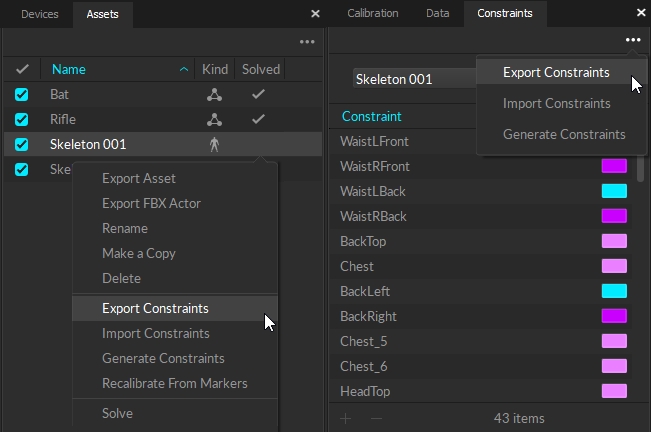
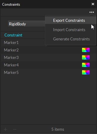
b) Right-click on the asset in the Assets pane and select Export Markers. Alternately, you can click the "..." menu at the top of the Constraints pane.
c) In the export dialog window, select a directory to save the constraints XML file. Click Save to export.
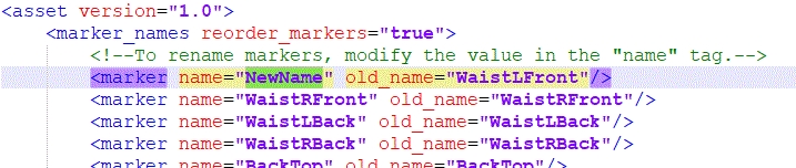
a) Open the exported XML file using a text editor. It will contain corresponding marker label information under the <marker_names> section.
b) Customize the marker labels from the XML file. Under the <marker_names> section of the XML, modify labels for the name variables with the desired name, but do not change labels for old_name variables. The order of the markers should remain the same unless you would like to change the labeling order.
c) If you changed marker labels, the corresponding marker names must also be renamed within the <marker_colors> and <marker_sticks> sections as well. Otherwise, the marker colors and marker sticks will not be defined properly.
a) To customize the marker colors, sticks, or weight, open the exported XML file using a text editor and scroll down to the <marker_colors> and/or <marker_sticks> sections. If the <marker_colors> and/or <marker_sticks> sections do not exist in the exported XML file, then you could be using an old Skeleton created before Motive 1.10. Updating and exporting the old Skeleton will provide these sections in the XML.
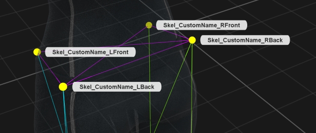
b) You can customize the marker colors and the marker sticks in these sections. For each marker name, you must use exactly same marker labels that were defined by the <marker_names> section of the same XML file. If any marker label was changed in the <marker_names> section, the changed name must be reflected in the respective colors and sticks definitions as well. In other words, if a Custom_Name was assigned under name for a label in the <marker_names> section <marker name="Custom_Name" old_name="Name" />, the same Custom_Name must be used to rename all the respective marker names within <marker_colors> and/or <marker_sticks> sections of the XML.
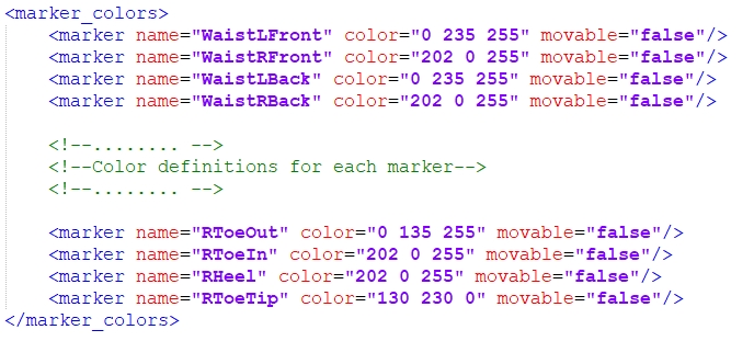
Marker Colors: For each marker in a Skeleton, there will be a respective name and color definitions under the <marker_colors> section of the XML. To change corresponding marker colors for the template, edit the RGB parameter and save the XML file.
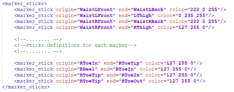
Marker Sticks: A marker stick is simply a line interconnecting two labeled markers within the Skeleton. Each marker stick definition consists of two marker labels for creating a marker stick and a RGB value for its color. To modify the marker sticks, edit the marker names and the color values. You can also define additional marker sticks by copying the format from the other marker stick definitions.
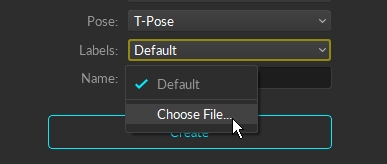
Now that you have customized the XML file, it can be loaded each time when creating new Skeletons. In the Builder pane under Skeleton creation options, select the corresponding Marker Set. Next, under the Constraints drop down menu, select "Choose File..." to find and import the XML file. When you Create the Skeleton, the custom marker labels, marker colors, and marker sticks will be applied.
If you manually added extra markers to a Skeleton, then you must import the constraint XML file after adding the extra markers or just modify the extra markers using the Constraints pane and Builder pane.
Note: For Skeletons, modified Marker XML files can only be used with the same Marker Set template. In other words, if you exported a Baseline (41) Skeleton and modified the constraints XML file, the same Baseline (41) Marker Set will need to be created in order to import the customized XML file.
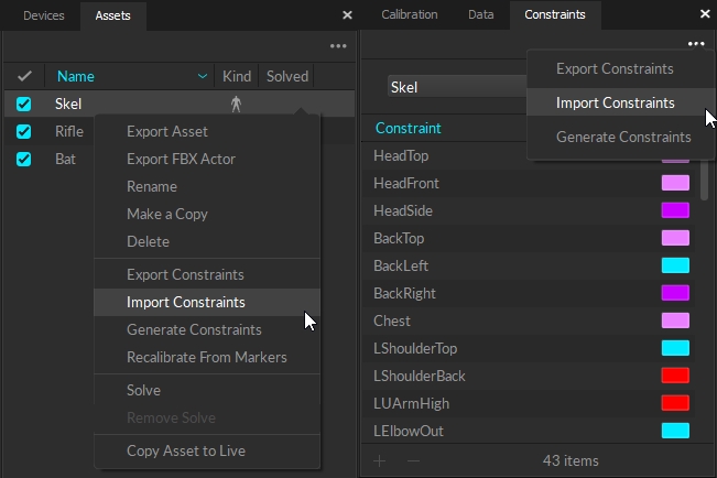
You can also apply a customized constraint XML file to an existing asset using the import constraints feature. Right-click on an asset in the Assets pane (or click the "..." menu in the Constraints pane) and select Import Constraints from the menu. This will bring up a dialog window for importing a constraint XML file. Import the customized XML template and the modifications will be applied to the asset. This feature must be used if extra markers were added to the default XML template.
This page provides instructions for using the Constraints pane in Motive.
The reconstructed 3D markers that comprise an asset are known as constraints in Motive. The Constraints pane provides information and tools for working with solver constraints for all asset types: Rigid Bodies, Skeletons, and Trained Markersets.
To open, click the button on the Motive toolbar.
By default, the Constraints pane will display the constraints for the asset(s) selected in either the 3D Viewport or the Assets Pane. If none is selected, the pane will display the constraints for -All- the assets in the Live volume or in the TAKE, when in edit mode.
The default view of the Constraints pane includes the Constraint (or label), Type, and Color. Right click the column header to add or remove columns from the view.
The Constraint column displays the marker labels associated with an asset. When the Asset selection is set to -All-, the asset name is included as a prefix to the marker label.
Skeleton templates include pre-defined labels that correspond to the marker's location and easily import into other pipelines for biomechanical analysis or animation.
Rigid Bodies and Trained Markersets are auto-labeled with generic, sequential labels.
The MemberID column displays the unique ID value assigned to each constraint. Typically, this is the original order of the constraints.
There are four types of constraints:
The ActiveID column allows you to view and modify Active Marker ID values. Active ID values are automatically assigned during asset creation or when adding a marker, but this gives you a higher level of insight and control over the process.
Weight is the degree to which an individual constraint influences the 3D solve of an asset. Specifically, adjusting the weight tells the solver to prefer that marker when solving the asset data with less than an optimal amount of marker information. For example, the hands are weighted slightly higher for the baseline and core skeleton Marker Sets to preference the end effectors.
Editing this property is not typically recommended.
To give a marker constraint a more meaningful name than the one auto-assigned when the asset is created, right-click the constraint name and select Rename from the context menu. Alternately, click twice on the constraint name to open the field for editing.
We recommend using the single asset view rather than -All- when relabeling markers from the Constraints pane.
You can also import a list of constraint properties, including names, for all asset types. See the section Export/Import Constraints, below and the page Constraints XML Files for more details.
Import label names for Trained Markerset assets with a quick copy and paste of text. This is useful if you've already mapped out the asset, either during the design phase or while placing the markers.
Copy the desired labels to the clipboard.
Left click the Constraints Pane.
Use Ctrl + V to paste the label names to the pane.
Please see the Labeling page for more information on using the Quick Labels tool.
By default, the Constraints column sorts by the asset definition, or the order in which the markers were selected when the asset was created. Click the column header to sort the column alphabetically in ascending or descending order, then click again to return to the default.
There are two methods to change the order of the constraints in the internal asset definition:
Right-click a constraint label and select an option to move up or down from its present location.
Drag and drop labels into the desired order.
Reordering constraints helps to define custom marker sequences for manual labeling. Changes made to the order will also be reflected in the Labels pane.
You can modify the following additional constraint settings from the Properties pane when a constraint is selected in the Constraints pane.
Position and Rotation: adjust the x/y/z coordinates of the constraint, in respect to the local coordinate system of the corresponding asset or bone.
Marker Diameter: view or change the diameter of an individual marker.
Constraint Type: Motive assigns the constraint type during the auto-label process. The user should not need to adjust this property.
Exporting constraints makes an XML file containing the names, colors, marker stick definitions, and weights for manual editing. Importing reads the (.xml) files made when exporting. Generating constraints resets the asset back to the default state, if applicable.
Please see the page Constraints XML Files for more information on working with these files.
The pane is locked to the selection whenever the button is active. Click the button to open the menu to select a different asset.
Marker: The constraint is associated with either a passive or active marker. Designated with the icon in the Type column.
Calibration Marker: Some biomechanical skeleton templates use calibration markers during asset creation that are subsequently removed prior to motion capture. In the 3D viewport, the constraints for these markers appear in red. Designated with the icon in the Type column.
6 DoF: The constraint formed by a Rigid Body on a skeleton created using a Rigid Body Skeleton template. Designated with the icon in the Type column.
IMU: The constraint associated with a sensor-fused IMU in a rigid body. Designated with the icon in the Type column.
The color column displays the color assigned to the constraint. The option with a rainbow effect links the constraint to the color defined by the asset.
To see constraints as well as markers in the 3D Viewport, click the Visual Aids button and select Marker Constraints -> Show All.
Select the marker(s) to add to or remove from the asset definition in the 3D Viewport then click either the Add button or the Remove button at the bottom of the pane.
Select the Markerset so the Constraints pane displays only its marker constraints. Alternately, click the button to deselect Lock Selection to Asset, and select the Markerset from the dropdown list.
The pasted labels will display at the bottom of the list. Click the Mouse Control button in the 3D Viewport or use the D hotkey to open the Quick Label tool to quickly assign the copied labels to the correct markers.
By default, constraints use the color selected in the asset properties, as indicated by the rainbow color icon.
Before making any changes to the x/y/z coordinates, save the current values by clicking the button to the right of the fields. Select Set as default. This will change the reset value from the Motive global default to the specific coordinates for the constraints.
You can also export configured constraints, or import them, using the Constraints pane. To do this, simply click on the context menu. There are options to export, import, and generate constraints.