Loading...
Loading...
Loading...
Loading...
Loading...
Loading...
Loading...
Loading...
Loading...
Loading...
This page provides instructions to use Active Batch Programmer to configure active components.
Active Batch Programmer provides a convenient way of programming multiple OptiTrack components including Active Tags, CinePucks, Pucks, and BaseStations.
In general, users should not need to use the batch programmer. Tags and Pucks are pre-configured for every set of devices that ships in the same order, and we ensure none of the Labels overlap.
The cases when you would need to reconfigure the active components are:
When you have purchased new Tags/Pucks to add to a system from a previous order.
When there is a need to change the RF communication channel to avoid interference.
When needed, multiple BaseStations can be connected to the same camera network, as long as they communicate through separate channels.
Please see the Active Components Hardware section for more details and specifications for Active Devices.
Windows 10 or 11
BaseStation: Mini USB Data Cable
Active Tag/Puck: Micro USB Data Cable
CinePuck: USB C Data Cable
To use IMU components, all of the devices, including the BaseStation, must have firmware version 2.x or above installed. To determine the version installed, attach each device in Read-Only Mode to display its current properties, including the firmware version.
If the installed firmware is an older version, please contact us for assistance with upgrading the firmware.
CinePucks on firmware version 3.x may require assistance from Support to configure.
Download the Active Batch Programmer installer from the Developer Tools section of the OptiTrack Downloads page.
Double-click to run the installer.
Review the End User License Agreement, check the box to agree to the license terms and conditions, then click Install.
The installer will copy a shortcut for the Active Batch Programmer to the Windows desktop.
Open Active Batch Programmer without any components connected.
Active Batch Programmer opens in Read-Only Mode by default. Once Read-Only Mode is turned off, the current settings are applied when a new device is attached, then powered on.
Stay in Read-Only Mode to view the active device's current configuration. Unchecking Read-Only Mode will apply the settings currently selected in the Active Batch Programmer when a device is connected.
For this reason, we recommend you always configure the settings you wish to apply first, before connecting any devices or turning off Read-Only Mode.
A batch of active components contains one BaseStation and the active components that connect to it. These components can be devices such as Pucks and CinePucks or sets of Active Tags.
Active Batch Programmer assigns a unique active label to each marker in the batch through labeling groups. A labeling group is a set of unique active marker labels that are programmed to the active IR LEDs on the device.
Applicable to Active Tags/Pucks only, Set Marker Labels is selected by default.
Marker labels are the active IDs assigned to individual markers, applied to all the markers on a single device or set of active tags as a group. The label group will increment as each new device is attached.
If needed, individual markers can be turned off on a device using the Disable Markers setting.
Always on Mode sets all the markers on the programmed device to 0. This causes the markers to strobe in sync with the exposure of the cameras, without an active pattern, making them appear like passive markers.
It's important there are no overlapping labels assigned within the same batch.
When reconfiguring marker labels, program ALL of the Tags and Pucks in the same session, so that labels do not overlap with other components in the system.
Select Set Radio to update the Radio Frequency (RF) Channel. The available RF range is 11-26. All devices in a single batch (BaseStation, Pucks, and/or Active Tags) must use the same RF channel.
Enter the RF Channel you wish to use. If programming a new device to attach to an existing BaseStation, make sure to assign the same RF channel used by the BaseStation to the new device.
The Uplink ID property is applied to active devices only and is unique to each device. This number increments as each new device is programmed.
Use the Signal Intensity slider to adjust the radio gain levels, as needed to address interference in the capture volume.
The Set Radio configuration applies to BaseStations as well as Pucks and Active Tags.
Select Set LED Options to adjust the brightness of the Active IDs.
Use the Custom Brightness setting to select a value between 0 and 100. The Default is 20.
Auto Brightness sets the value to 50.
Once the settings are configured, you are ready to begin the first batch.
Uncheck Read-Only Mode (just report existing configuration).
With the device powered off, attach the BaseStation, Puck or Active Tag to the PC running Active Batch Programmer, using the following cable type:
BaseStation: Mini USB data cable
Active Tag/Puck: Micro USB data cable
CinePuck: USB C data cable
Skip updating the BaseStation if it's already set to the RF Channel you wish to use.
Power on the device and wait for Active Batch Programmer to update the Current Batch information (Active Tags, CinePucks, and Pucks only) and the Log.
Once the device is configured, disconnect it and attach the next device. Repeat until all devices in the batch are configured.
The Current Batch field displays summary information about the label groups applied to the devices in the batch. This allows the user to easily track which devices are included in the batch and ensure that duplicate label groups are not assigned.
Note that the Next Label Group value has advanced automatically.
To prevent overlapping label groups, we recommend programming all the devices for each BaseStation in a single batch.
Click Start New Batch to program additional BaseStations and devices.
Monitor the Log while connecting components to make sure configurations are applied successfully. The Log displays detailed information about the device in both read-only mode and when updates are made.
Firmware version
Existing configuration
Device serial number
Details of all the changes applied
Read-only information is displayed in gray with a [debug] tag, while changes are shown in black with the [info] tag. If needed, click in the log pane to select and copy the log to paste it into a text file.
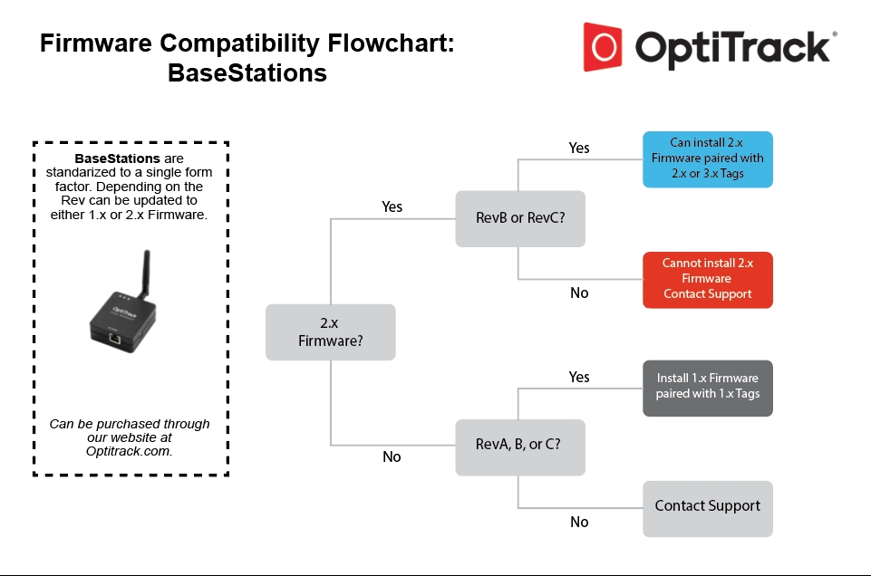
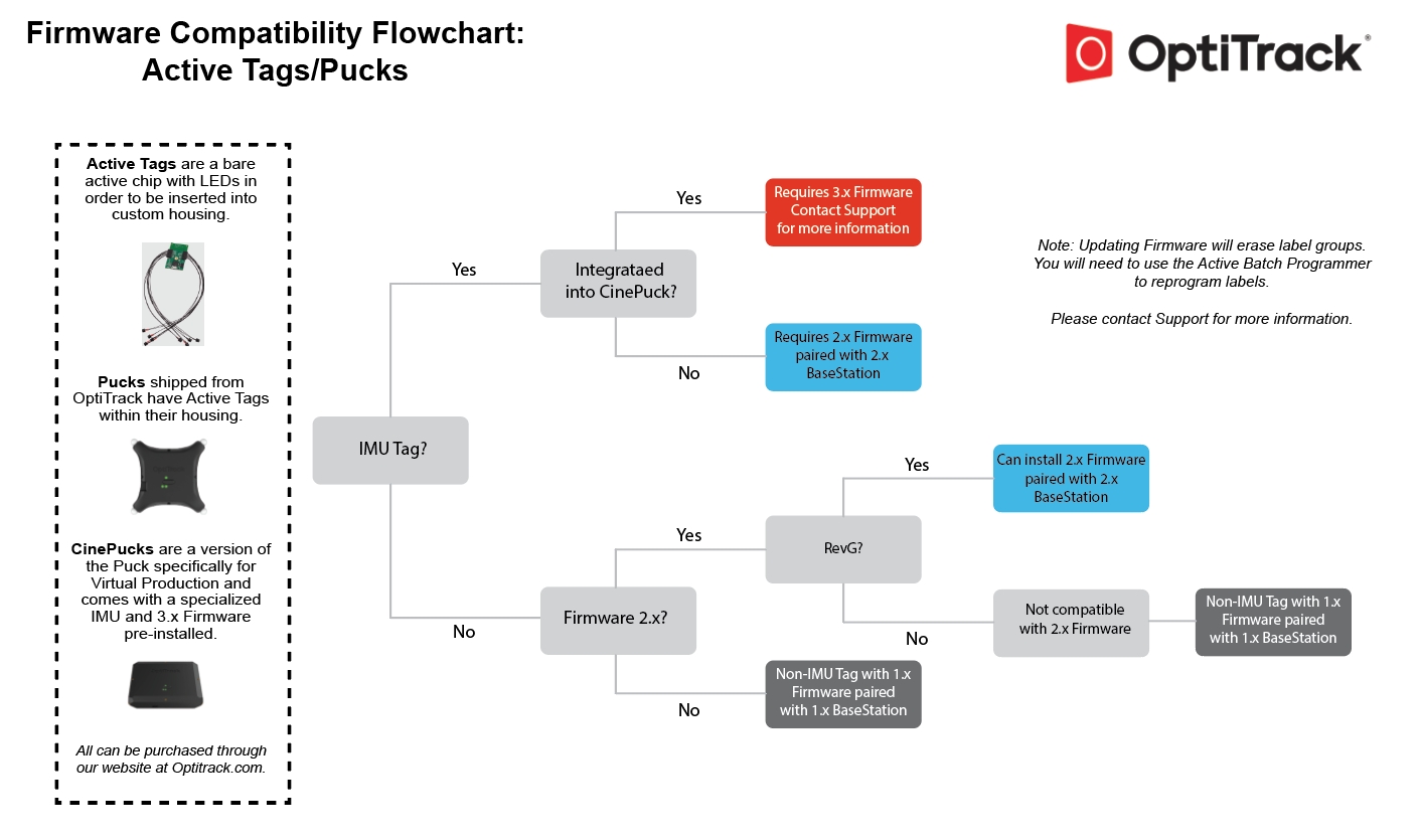
Firmware Compatibility Chart
The charts below outline the firmware versions available for BaseStations and Active Tags/Pucks. With the exception of the CinePuck, the active devices and the BaseStation must be on the same firmware version. The CinePuck uses 3.x firmware and is compatible with BaseStations on 2.x.
For Active Tags specifically, if the device doesn't have an IMU then it's compatible with 1.x. firmware If it has the first version of an IMU, then it is compatible with 2.x. And, if it has an upgraded IMU (i.e., a CinePuck), then it is compatible with 3.x.
The following specifications apply for active IR LEDs on both the Tags and the Pucks.
850 nm IR spectrum.
8 LEDs with removable diffusers (9.5mm, 3/8", diameter) on four corner LED locations
Illuminations synchronized with camera exposures
Illumination angle:
With Diffuser: ±135°-Bare LED without diffuser: ±70°
Puck Body Dimensions
Dimensions without diffusers
Width: 96mm (~3.75”)
Length: 96mm (~3.75”)
Height: 20mm (~0.75”)
Dimensions with diffusers
Width: 104mm (~4.10”)
Length: 104mm (~4.10”
Height: 20mm (~0.75”)
Weight
2.24 oz (64g)
Attachment
Slots for (2) 7/8th inch velcro/elastic straps on the underside of the puck
¼ - 20 camera mount style thread on bottom for other convenient mounting solutions
Battery
1200 mAh Lithium polymer battery
Expected life 10 hrs at nominal operating conditions (cameras operating at 180Hz, with 500 𝞵s exposure setting). Lower frame rates or exposure times can extend battery life.
Charging
5V micro USB power source required to charge
~ 3hrs zero to full charge
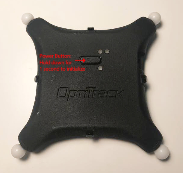
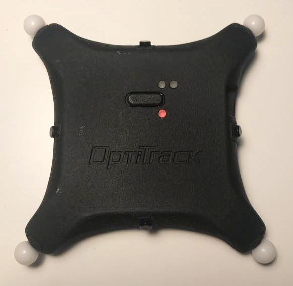
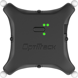
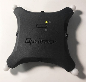
Power on: Press down on the button for ~1 second to turn on the puck. It will illuminate the top LED in orange for a few seconds until it initializes.
Power off: Hold down the button for ~2 seconds
Battery status check: Press down on the button while the puck is powered on to illuminate the battery status LED.
Bootloader: Pressing down on the button for longer than 3 seconds will set the puck at the bootloader state. At this state, both the top and bottom LED will turn orange, and the puck will not be operational. To exit out of this, you can just power off the puck and turn it back on.
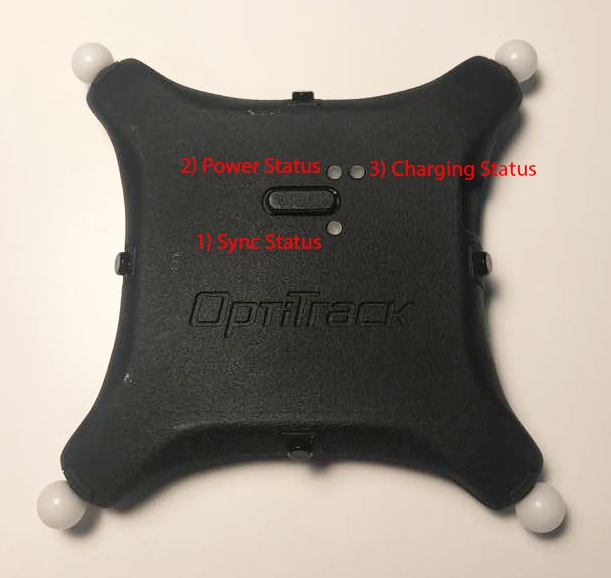
Three plainly visible status LEDs for indication of battery status, sync status, and charging status.
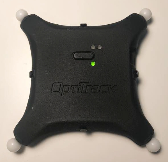
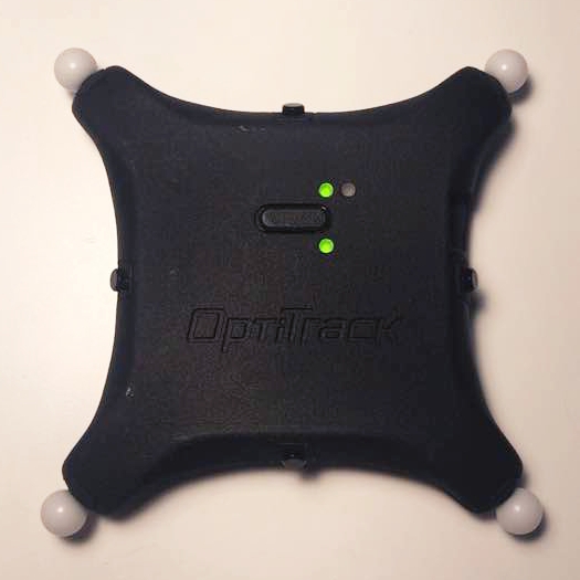
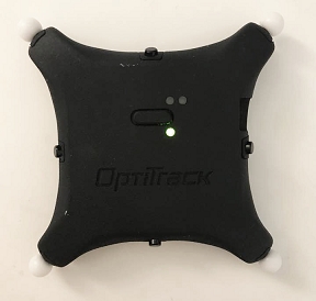
The bottom LED indicates the sync status. When the puck is successfully synchronized with a base station, it will start receiving sync packets, and this bottom LED will start blinking green roughly at 10 Hz rate:
Blinking green: Sync packets are being received.
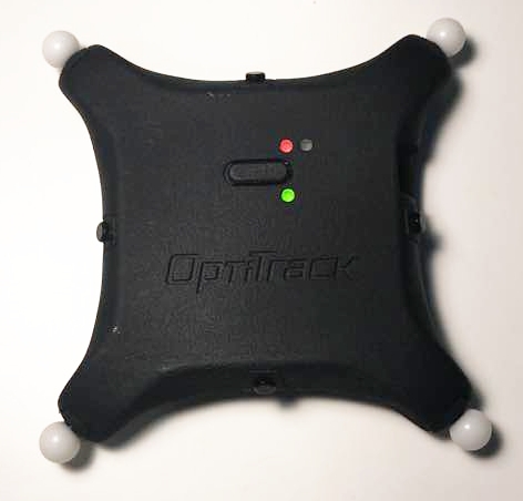
Red: The first sync packet has not been received yet. At this stage, the puck is waiting for the packet.
Continuous green: The first packet was received for initial synchronization but sync packet is no longer being received.
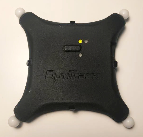
Normal: illuminates in green and blinks every 5 seconds. You can also press on the power button to check the battery.
Color indicator:
Green (Good charge) - battery sufficient
Yellow (getting low) - ~1 hour left
Red (extremely low) - ~20 minutes left until power is depleted
Red: Charging / Idle
Green: Fully Charged
Yellow/orange: Bad battery. Stop using the puck and contact support.
When connected to the OptiTrack system, the properties for the Active puck and its associated Base Station are shown in the Devices Pane. Please see the Devices Pane page for more details.
Please see the Builder pane page for instructions on creating a rigid body asset, and the page IMU Sensor Fusion for instruction on pairing the active tag to an asset.
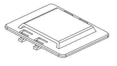
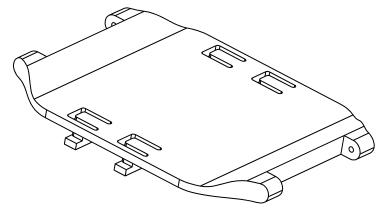
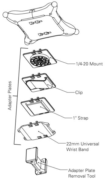
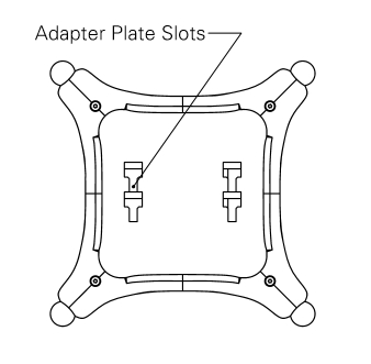
Each Active Puck has four slots on the back where an accessory adaptor plate can be fitted into. These adapter plates can be purchased from our webstore, and they provide the Active Puck various mounting options for attaching onto different types of objects.
There are four different types of adapter plate accessories that can be fitted onto an Active Puck:
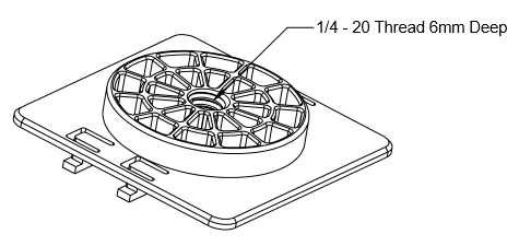
Adapter plate with a 1/4-20 mount
Adapter plate with a clip
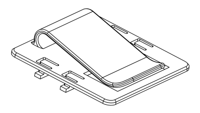
Adapter plate with a 1" strap slot
Adapter plate with 22mm wristband socket.
To mount an adapter plate onto an Active Puck, simply insert the four T-shaped latches of the adapter plate into the four slots on the back of an Active puck. Once the latches have been fully inserted, slide the adapter plate towards the center of the puck until you hear a click.
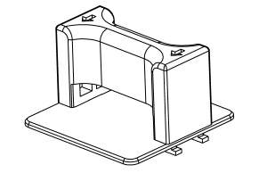
Once an adapter plate is latched onto an Active Puck, a removal tool must be used to detach the adapter plate. To use the removal tool, insert the four hooks on the removal tool into the four slots on the adapter plate. Then use the attached removal tool to slide and pull the adapter plate out from the Active Puck.
If any of the four adapter plate accessories do not fit for the object you are tracking, you can also use the attached CAD file to modify and 3D print customized adapter plates.
Adapter Plate CAD file (STEP):
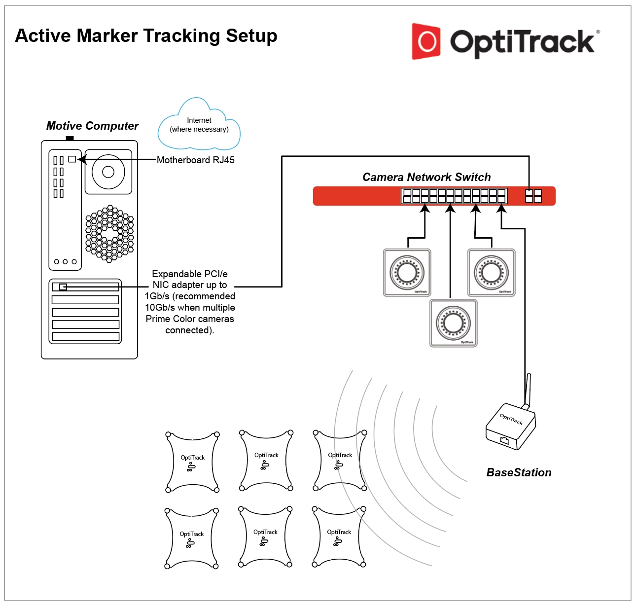
Instructions to setup and use the OptiTrack active marker solution.
The OptiTrack Active Tracking solution allows synchronized tracking of active LED markers using an OptiTrack camera system. Consisting of a BaseStation and one or more active devices such as the "users choice" Active Tags that can be integrated in to any object, the Active Puck which can act as its own single Rigid Body, or the CinePuck, designed to support Virtual Production and broadcast studios.
The BaseStation emits RF signals to the active markers, allowing precise synchronization between camera exposure and illumination of the LEDs. Each active marker is uniquely labeled in Motive, allowing more stable Rigid Body tracking since active markers will never be mislabeled and unique marker placements are no longer required for distinguishing multiple Rigid Bodies.
To configure assets that contain active tags and an Inertial Measurement Unit (IMU) such as Pucks and CinePucks, please refer to the article IMU Sensor Fusion.
Notes:
This guide is for OptiTrack active markers only. Third-party IR LEDs will not work with the instructions provided on this page.
This solution is supported only with Ethernet camera systems (Slim 13E or Prime series cameras). USB camera systems are not supported.
Active Tracking works with Motive versions 2.x or 3.1 and above. It is not available in version 3.0.
This guide covers active component firmware versions 1.0 and above, which includes all active components that were shipped after September 2017. For active components shipped prior to September 2017, please see the compatibility notes page for more information about firmware compatibility.
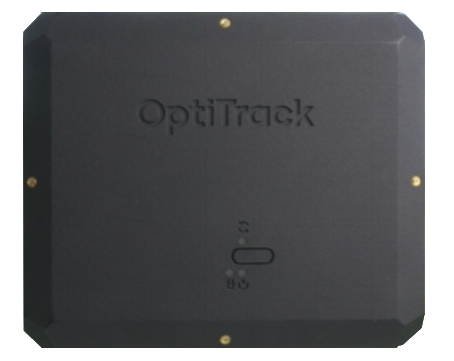
Emits radio frequency signals to synchronize the active markers.
Powered by PoE, connected directly via Ethernet cable to one of the switches in the camera network.
Please see the BaseStation page for product specifications and more information.
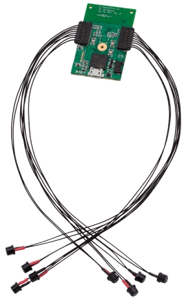
Connects to a USB power source to illuminate the active LEDs.
Receives RF signals from the Base Station and synchronizes illumination of the connected active LED markers accordingly.
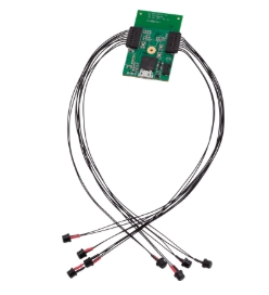
LEDs come in bundles of 4. One or two bundles can be connected to each tag, for a maximum of 8 Active LEDs per Tag.
Each LED emits 850 nm IR light.
Size: 5 mm (T1 ¾) Plastic Package, half angle ±65°, typ. 12 mW/sr at 100mA
Please see the page Information for Assembling the Active Tags for more information.
An active tag self-contained into a trackable object, the Active Puck provides 6 DoF information for any object to which it's attached. Pucks include a factory installed Active Tag with 8 LEDs and a rechargeable battery with up to 10-hours of run time on a single charge.
For product specifications and other information about the Puck, please see the page Active Puck.
To configure Pucks that contain an Inertial Measurement Unit (IMU), please refer to the page IMU Sensor Fusion.
Similar to the Active Puck, the CinePuck is designed to attach to a movie camera to support In-Camera Virtual Effects, often referred to as InCam VFX or ICVFX. Please see the page Unreal Engine: OptiTrack InCamera VFX for more information.
For product specifications and other information about the CinePuck, please see the page CinePuck.
All CinePucks contain an Inertial Measurement Unit (IMU). Please refer to the page IMU Sensor Fusion for instructions to configure the CinePuck.
Active tracking is supported only with an Ethernet camera system (Prime series or Slime 13E cameras). For instructions on how to set up a camera system, please refer to the Ethernet Camera Network Setup chapter.
Connect the BaseStation to one of the PoE switches within the camera network.
Metal and other dense materials can cause interference that may reduce the BaseStation's range. For best performance, place the base station near the center of the tracking space, with unobstructed lines of sight to the areas where the Active Tags will be located during use.
Do not place external electromagnetic or radiofrequency devices near the Base Station.
When Base Station is working properly, the LED closest to the antenna should blink green when Motive is running.
The number of Active Devices that can attach to a a single BaseStation is determined by the system frame rate and the divisor applied to the BaseStation. The BaseStation Load Capacity table on the BaseStation page shows the IMU maximum for common frame rates and divisors.
BaseStation LEDs
Communication Indicator LED: When the BaseStation is successfully sending data and communicating with the Active Pucks, the LED closest to the antenna will blink green. If this LED turns red, it indicates that the BaseStation failed to establish a connection with Motive.
Interference Indicator LED: The middle LED indicates if there are other signal-traffics on the respective radio channel and PAN ID that might be interfering with the active components. This LED should stay dark in order for the active marker system to work properly. If it flashes in red, consider switching both the channel and PAN ID on all of the active components.
Power Indicator LED: The LED located at the corner indicates power for the BaseStation. This LED may be disabled on BaseStations with the latest firmware, but on older BaseStations this LED may light up in red to indicate the device has power.
Connect two sets of active markers (4 LEDs in each set) into a Tag.
Connect the battery and/or a micro USB cable to power the Tag. The Tag takes 3.3V ~ 5.0V of inputs from the micro USB cable. If powering with a battery, use only the batteries supplied by OptiTrack. To recharge the battery, connect it to the Tag then connect the micro USB cable to a power source.
To initialize the Tag, press the power switch once. Be careful not to hold down on the power switch for more than a second, as this will initialize the device in the firmware update (DFU) mode. If it initializes in the DFU mode, which is indicated by two orange LEDs, just power off and restart the Tag. To power off the Tag, hold down on the power switch until the status LEDs go dark.
Once powered, you should be able to see the illumination of IR LEDs from the 2D reference camera view.
Puck Setup
Press the power button for 1~2 seconds and release to power the device on.
The top-left LED will turn amber while the Puck initializes. The bottom LED will turn green when the Puck has made a successful connection with the BaseStation, at which point the top-left LED will start blinking green to indicate the sync packets are being received.
For more information, please read the Active Puck page.
As shipped, BaseStations and active devices will connect to the OptiTrack system without additional configuration by the user. Some circumstances may require a configuration update, such as when adding new BaseStations to an existing system or to change the RF channel or BaseStation divisor rate.
The BaseStation is configured outside of Motive, using one of the following programs:
Please see the linked pages for more details on configuring the BaseStation.
The following settings are relevant to Active Tracking.
Settings → Live Pipeline → Solver Tab -> Trajectorizer
Default value: 12
This setting adjusts the complexity of the illumination patterns produced by active markers.
In most applications, the default value is sufficient for high quality tracking results. If a large number of Rigid Bodies are tracked simultaneously, increase the value to allow more combinations of illumination patterns on each marker.
If this value is set too low, duplicate active IDs can be produced, should this error appear increase the value of this setting.
Default value: 3
This sets the number of rays required to establish the active ID for each on frame of an active marker cycle.
The default value works well for the majority of applications. If this value is increased and active markers become occluded, it may take longer to reestablish those markers in the Motive 3D Viewport.
Settings → Views → 3D Tab -> Markers
The Markers section sets the default color assigned to different types of markers. Markers that are part of an asset will use the color selected in the visuals section of the Asset Properties.
Default color: blue
The Active setting distinguishes active markers from passive in the Motive 3D Viewport.
Default color: white
Intermediate markers are active markers in a temporary state prior to being identified in Motive. These markers change to the active marker color (or the asset color, if different) once Motive identifies them.
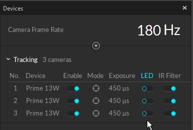
The following camera settings yield the best tracking results for active LED markers.
Set the camera exposure a bit higher than you would when tracking passive markers. This allows the cameras to better detect the active markers. The optimal value will vary depending on the camera system setup, but in general, set the camera exposure between 400 ~ 750, microseconds.
When tracking active markers only, the cameras do not need to emit IR lights. In this case, you can disable the LED lights in the Devices pane.
Information about BaseStations and Active Tags is available in the Devices pane. Select an item in the Devices pane to view its properties in the Properties pane. All values are read-only.
BaseStations are listed in the Synchronization category of the Devices pane. Available display options are the Device (device type) and the Serial number.
The Active Batch Programmer is required to view additional settings or make configuration changes to a Base Station and its associated active devices.
Active devices that connect to the camera system via BaseStations are listed in the Active Tag section. The following properties are available:
Name: the tag name consists of two numbers, the the RF channel used to communicate with the Base Station followed by the unique Uplink ID assigned to the device.
Paired Asset: If the tag is paired to an asset, the asset's name will appear here. Otherwise, the field will display N/A.
Aligned: shows the status of the Active tag.
BaseStation: displays the serial number of the connected BaseStation. This column is not displayed by default; right-click the header to add it.
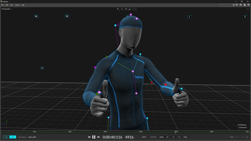
Active Markers are reconstructed and tracked in Motive automatically. The unique illumination pattern ensures each active marker is individually labeled, with an Active ID assigned to the corresponding reconstruction. This applies whether or not the Active Marker is part of an asset.
The Active IDs can be monitored in the 3D Viewport as part of the marker label, in both Live and Edit modes. To view:
Enable the Marker Labels and the Active ID options.
Active IDs that are not part of an asset:
The same Active IDs after asset creation:
Rigid body definitions created using Active Markers will search for specific Active IDs along with the marker placements to track the Rigid Body. See below for more details.
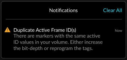
Duplicate active frame IDs
This Notification displays if more than one marker has the same ID. Duplicate IDs may cause errors during 3D reconstruction.
If this occurs, please contact support for assistance.
As noted above, rigid body definitions created from reconstructions with Active IDs will search for those IDs to solve the Rigid Body. This means active markers can be placed in perfectly symmetrical marker arrangements across multiple Rigid Bodies without the risk of labeling swaps.
For more information, please see the following pages:
To create or modify a Rigid Body asset, please see Rigid Body Tracking.
To configure Pucks and CinePucks with IMU sensors, please see IMU Sensor Fusion.
This page reviews the active finger marker set and how to set it up.
The active finger Marker Set utilizes the tracking capability of active markers and the active labeling features to accomplish tracking of both the hands and the fingers. These Marker Sets require the active marker tracking solution and a set of Tag(s). Wired from an active Tag, each active marker must attach to the expected locations. For each hand, 8 active markers are needed, with 2 passive markers attached at the wrist.
Manus VR Gloves
Alternatively, you can also use Manus VR Gloves for tracking the fingers. For more information, refer to the Manus Glove Setup page.
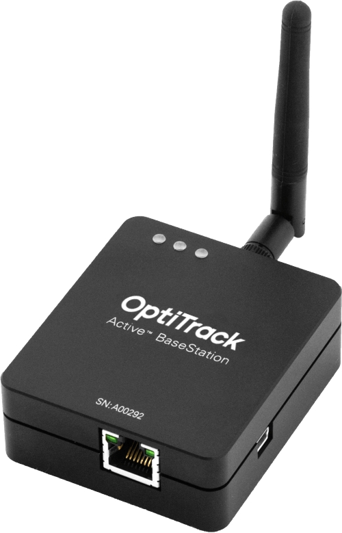
The Active BaseStation
Active Tag(s) with active markers.
A way to attach active markers onto the hands (e.g., gloves).
Baseline + Active Fingers (57)
Core + Active Fingers (62)
Right Hand + Active Fingers (10)
Left Hand + Active Fingers (10)
Please note that the numbers listed in the Marker Set names are the total number of markers needed, including both active and passive markers.
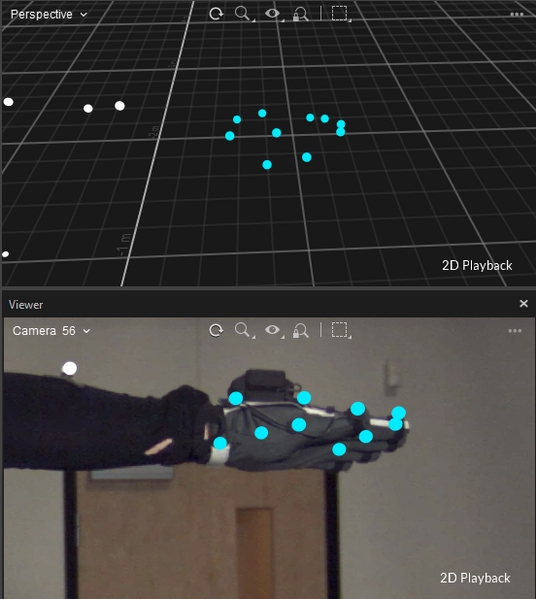
Total of 10 markers will be attached on each hand (8 Active markers and 2 passive).
Tags: Attach Tags to each hand for the active LEDs.
Passive Markers (2): Attach the 2 passive markers to both sides of the wrist, directly on the joints of either side along the wrist flexion point.
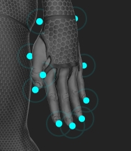
Active Markers (8): Each Tag connects up to 8 active markers. Position the wired active markers at the tip of all five fingers (5), one each on the knuckle of the index finger and the pinky finger (2), and place the remaining active marker on the inside of the bottom thumb joint.
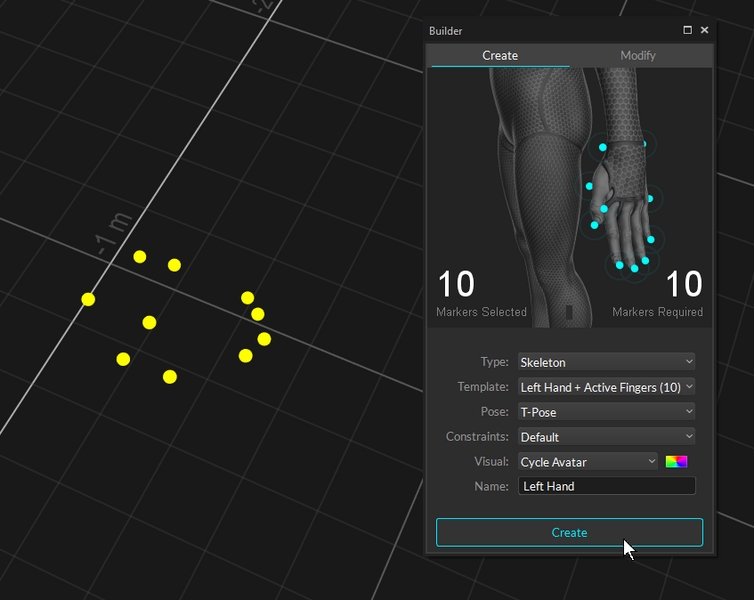
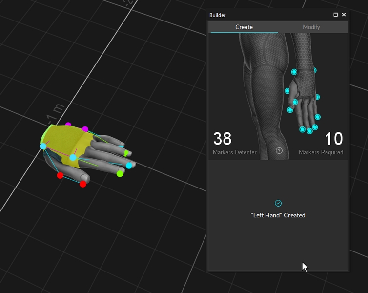
Steps for creating an active finger Marker Set is the same as the other skeleton Marker Set:
Open the Builder pane and select the desired hand Marker Set under the drop-down menu.
Make sure all of the markers are placed in the correct positions. For the Core + Active Fingers (62) Marker Set, please make sure the passive full body tracking markers are also placed on the person's body.
Once the markers have been placed, ask the subject to strike the calibration pose.
Select the finger markers in the 3D viewport.
The Marker Detected must match Marker Required in the Builder pane.
Click Create.
This page provides instructions on integrating Manus gloves with an OptiTrack motion capture system.
Starting from Motive 3.0 and above, these gloves can be integrated into Motive. This allows for easy integration of the external glove tracking system directly in Motive so that it can be used in tandem with the OptiTrack system to provide a more comprehensive tracking solution.
Required Components
Manus Glove Prime X and Manus Glove Dongle.
Manus Core and Dashboard software
Motive 3.0 or above
(optional) MoCap suit and markers for full body capture.
Important Note
At the time of writing, the integration is supported for Manus Glove Prime X models only.
Sampling Rate: Manus gloves run at a fixed sampling rate of 90Hz. If the camera system is set to run at a higher frame rate higher, Motive will pad the missing samples in the glove data with previous samples.
Sync: Manus gloves do not support hardware synchronization. Thus, Motive uses a software synchronization scheme to attempt to keep Manus glove 'as close as possible' to mocap data.
Manus Dongle: Plug the Manus dongle on a separate USB bus from the one used to connect the USB Security Key. If both dongles are connected into the same bus, it may cause conflicts with Motive activation.
Before using Manus VR gloves in Motive, please ensure all gloves have been paired, calibrated and are able to report data from Manus software. This is a crucial first step for the successful use of Manus Gloves with Motive software.
Please note that steps required for setting up the glove may change depending on Manus Software versions. For the latest information, please refer to the manufacturer documentation.
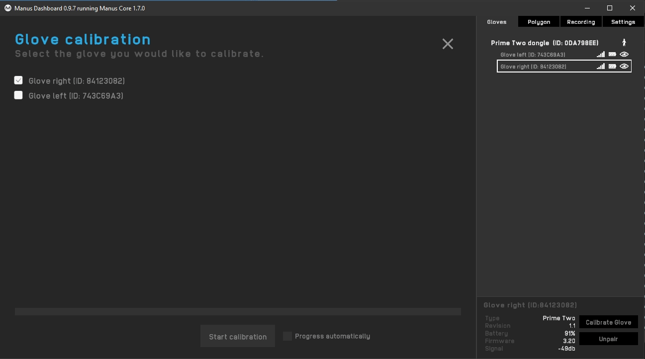
Start the Manus Dashboard software.
Insert the Manus Glove Dongle(s) onto the computer. Do not connect the dongle into the same USB bus used by the USB Security Key as it can cause conflicts with device detection.
Power on the Manus Gloves.
(optional) You may need to pair the glove with the dongle if needed. The gloves should come already paired.
Calibrate each glove. This involves going through a series of hand gestures to calibrate the glove to the user’s hand. This helps give more robust finger solve data.
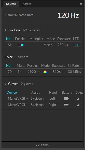
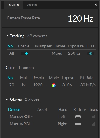
Start Motive and the gloves should appear in the Devices pane.
Note: We suggest that Manus Dashboard be closed to resolve some performance issues in Motive.
Before starting Motive, please make sure to launch Manus Dashboard and Manus Core software first.
Launch Motive. If the Manus VR is properly set up on the computer, connected gloves will be listed under the Devices pane.
Use the Builder pane to define a Skeleton asset in Motive. You can use any Skeleton model that is not designed to track fingers using motion capture data. The recommended Skeletons models to use are the Core 50 or Baseline 41.
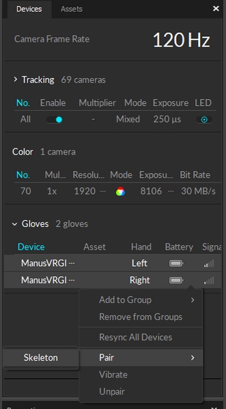
After a Skeleton has been defined, pair the Skeleton to the glove device. Open the Devices pane, right-click on the listed glove device, and pair it to the Skeleton as shown in the screenshot below.
Once the glove has been configured and paired with the created Skeleton, the fingers will be tracking in Motive.
Once Motive starts tracking the glove, the finger tracking data can be outputted for various applications. Real-time finger data can be streamed into any NatNet client, and recorded finger data can be exported into other file formats. For instructions on outputting tracking data from Motive, refer to the following pages:
We strongly recommend you use our Active Batch Programmer instead of PuTTY. Instructions on how to use the Active Batch Programmer can be found here: Using Active Batch Programmer. Our Active Batch Programmer automates many of the settings found below and therefore is safer and more convenient for use.
This guide is intended for advanced users or those under the guidance of the OptiTrack Support Team. Your OptiTrack Active hardware should arrive fully configured and ready for immediate use. In most cases, you should not need to modify its configuration. If configured incorrectly, tracking may perform poorly, or may cease to function entirely. Do not attempt to modify the configurations of your OptiTrack Active hardware unless you have been instructed on how to do so by an OptiTrack Support Engineer.
The BaseStation and Active Tag can both be connected to a computer via USB, and expose a virtual serial port. You can connect to this serial port using a terminal application in order to view and modify the configuration of the devices.
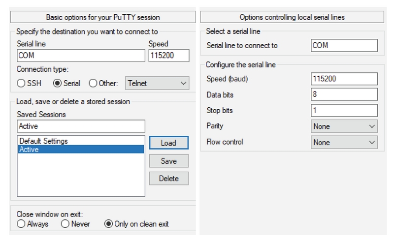
A popular choice of terminal application for Windows is the freely available PuTTY, which the latest version can be downloaded here and will be used in this guide.
Note that the UI of PuTTY may look slightly different for each version, however, all of the relevant settings will be present.
After a successful download of PuTTY, we'll want to create a saved session that we can use every time we boot up PuTTY for our Active hardware configurations.
Instructions
Start PuTTY.
Choose the Serial option under the "Connection Type" section.
Enter 115200 into the Speed field.
Under Saved Sessions enter an appropriate name like "Active" or "Tag Settings".
After everything is entered correctly click the Save button. This will populate your saved name below Default Settings.
The next time you boot up PuTTY you can select the saved session and click Load to load the settings we set up above. You can access more detail information about the serial connection by clicking the Connection > Serial option in the Category section on the left.
When connecting to an OptiTrack Active device you'll need to input the correct COM# port into the "Serial Line" section.
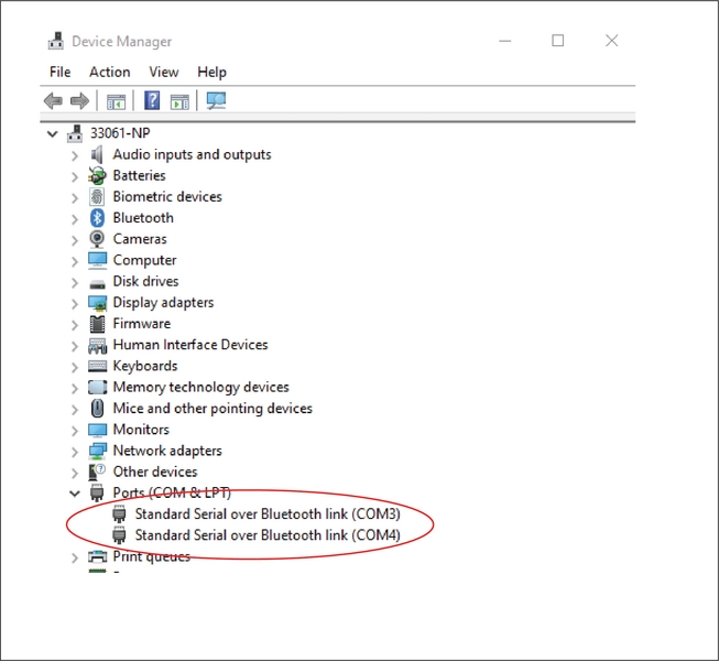
When you're ready to start programming your Active tags you need to verify their class-compliant virtual serial port to enter into the Serial line in PuTTY. To do this you'll need navigate to the Device Manger for any Windows machine.
From the Device Manger window you can click the dropdown arrow for Ports. This will show a list of all the COM ports that are plugged into your machine.
The easiest way to find out which COM number is associated with your Active Tag is to plug in the Active Tag and see which new COM port appears.
Once you have this number (ie. COM3, COM4, etc.), you can navigate back to PuTTY to enter this port into the Serial line text field.
Now that we have all the settings we need to properly interface with Active Tags and BaseStations, we can open a PuTTY session.
To do this we simply load the settings configured above and then click Open.
This will open a command terminal where we can implement commands to configure both the Active Tags and BaseStations.
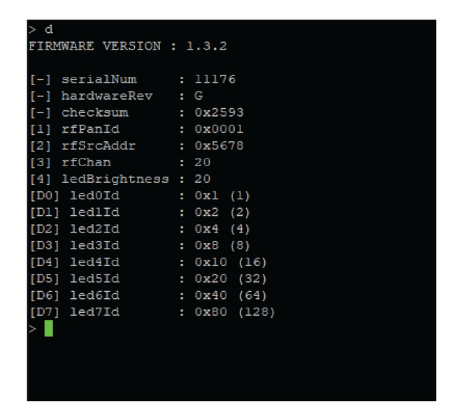
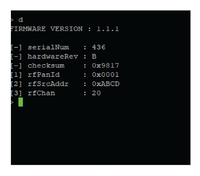
There are three serial commands that we'll be concerned about for this application: d, s, and v.
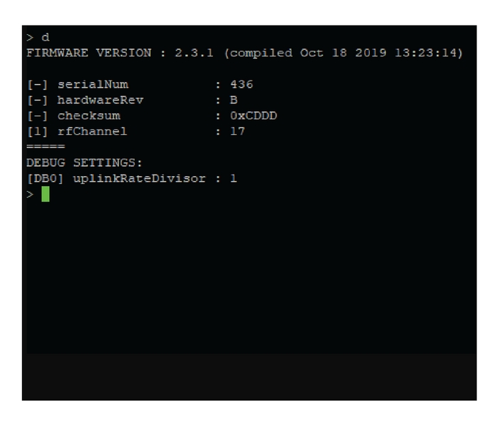
This command takes no parameters, and outputs a listing of all configuration options and their current values. Each configuration option is listed on its own line, starting with its ID (surrounded by square brackets), followed by its name, and finally its current value.
The ID is used to refer to the options when modifying their values (described below); if the ID is displayed as a dash, this means the value cannot be changed.
If the value begins with the prefix “0x”, this means the value is displayed in hexadecimal (base 16); otherwise, the value is a regular decimal (base 10) number.
This command takes two parameters (separated by spaces), and is used to modify the value of a configuration option.
The first parameter, as described above, is the ID of the configuration option you want to modify.
The second parameter is the new value to use for the specified option. The new value can be provided in either decimal or hexadecimal; if hexadecimal, the value should be prefixed with “0x”.
As an example, the command s 1 2 will set the option with ID 1 to the value of 2. Similarly, the command s 1 0xF will set the option with ID 1 to the value of 0xF (hexadecimal), or 15 (decimal).
This command takes no parameters, and writes the current configuration to the flash memory of the device. This should always be performed before closing a PuTTY session if you wish to save the configuration.
The v command is required to preserve any changes you’ve made to the configuration since the last time you saved. If you do not issue the save command, your configuration changes will be lost the next time the device is powered off.
Some of the options in PuTTY change depending on the firmware version you use with Active hardware. These options are for Firmware Version 1.x.
When configuring a BaseStation there are only a couple of options we would need to worry about for most setups. It's good practice to first configure a BaseStation and then program Active Tags around the BaseStation's settings.
BaseStation Commands
[1]: rfPanId
Default: 0x0001
This is the 16-bit PAN (personal area network) identifier used for wireless communication.
The PAN ID is used to filter traffic at the hardware level, and different PANs may be used to partition a single wireless channel into multiple separate logical networks. This may, for example, be useful if you needed to use two separate OptiTrack Active systems in close proximity. However, in general, the use of different wireless channels (see option [3]: rfChan below) should be preferred, rather than using multiple PANs on same wireless channel.
The PAN ID and channel values configured on the BaseStation must match the values configured for every Tag that is intended to be used with that BaseStation.
[2]: rfSrcAddr
Default: 0xABCD
This is the 16-bit wireless address of the BaseStation. You should not need to change this.
[3]: rfChan
Default: 20
This is the radio channel used for wireless communication. The range of valid channels is 11-26. The frequency in MHz for the channel ch is given by 2405 + 5 · (ch - 11).
You may wish to change the radio channel if you have determined that you’re encountering poor RF performance due to external interference, or if you want to operate multiple OptiTrack Active systems in close proximity.
The PAN ID and channel values configured on the BaseStation must match the values configured for every Active Tag that is intended to be used with that BaseStation.
When configuring Active Tags, you'll want to match the rfPanId and rfChan to the BaseStation. If these do not match then the Active Tags will not properly synchronize to your OptiTrack system.
Active Tag Commands
[1] rfPanId
Default: 0x0001
Refer to the description in the section above: Firmware Version 1.x > BaseStation Commands > rfPanID.
The PAN ID and channel values configured on the BaseStation must match the values configured for every Tag that is intended to be used with that BaseStation.
[2] rfSrcAddr
Default: 0x5678
This is the 16-bit wireless address of the Tag. You should not need to change this.
[3] rfChan
Default: 20
Refer to the description in the section above: Firmware Version 1.x > BaseStation Commands > rfChan.
The PAN ID and channel values configured on the BaseStation must match the values configured for every Tag that is intended to be used with that BaseStation.
[D0] led0Id … [D7] led7Id
Default: 0x0 (0)
These settings are used to specify the active ID for each of the 8 active marker LEDs connected to the Active Tag. The default value of 0 is a special value indicating that the LED is not actively labeled and behaves as though it were a passive marker (with its LED on time synchronized with the exposure of the cameras).
The LED IDs are preprogrammed when they are sent out. The Active Batch Programmer is the best way to change these settings. Only use this setting under the guidance of an OptiTrack Support Engineer.
BaseStation Commands
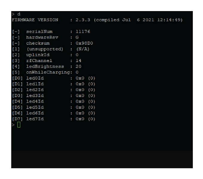
[1]: rfChannel
Default: 20
This is the radio channel used for wireless communication. The range of valid channels is 11-26. The frequency in MHz for the channel ch is given by 2405 + 5 · (ch - 11).
You may wish to change the radio channel if you have determined that you’re encountering poor RF performance due to external interference, or if you want to operate multiple OptiTrack Active systems in close proximity.
When configuring Active Tags, you'll want to match the rfChannel to the BaseStation. If the two devices do not match then the Active Tags will not properly synchronize to your OptiTrack system.
Active Tag Commands
[2]: uplinkId
Default: 0
The uplinkId identifies the Active Tag label class that the Tag belongs to. This allows for Active Tags to be uniquely identified when there are multiple Active Tags with the same form factor in the same volume.
[3] rfChan
Default: 20
Refer to the description in the section above: Firmware Version 2.x > BaseStation Commands > rfChannel.
[4] ledBrightness
Default: 20
You can choose to increase or decrease the LED brightness on each Active Tags active markers collectively. This will control the brightness of all of the LEDs together as a unit incase the cameras are having difficulty tracking. However, it is recommended to change physical characteristics of the cameras (ie. aperture), or of the volume (ie. blocking out excess light), or increase the exposure of the cameras in Motive prior to altering this setting.
[5] onWhileCharging
Default: 1
This setting allows for a powered Active Tag to remain on when plugged into power. It is useful in setups where the Active Tag is mounted to an object that can supply power, thus ensuring the Active Tag will not turn off or run out of battery.
1 denotes that a powered Active Tag remains on when plugged into power, 0 denotes that when a powered Active Tag is plugged into power, it will shut off while charging.
[D0] led0Id … [D7] led7Id
Default: 0x0 (0)
These settings are used to specify the active ID for each of the 8 active marker LEDs connected to the Active Tag. The default value of 0 is a special value indicating that the LED is not actively labeled and behaves as though it were a passive marker (with its LED on time synchronized with the exposure of the cameras).
The LED IDs are preprogrammed when they are sent out. The Active Batch Programmer is the best way to change these settings. Only use this setting under the guidance of an OptiTrack Support Engineer.
Currently, there is not a 3.x firmware version for BaseStations. Please refer to 2.x instructions above.
When configuring Active Tags, you'll want to match the rfPanId and rfChan to the BaseStation. If these do not match then the active tags will not properly synchronize to your OptiTrack system.
Active Tag Commands
[2]: uplinkId
Default: 0
The uplinkId identifies the Active Tag label class that the Tag belongs to. This allows for Active Tags to be uniquely identified when there are multiple Active Tags with the same form factor in the same volume.
[3] rfChan
Default: 20
Refer to the description in the section above: Firmware Version 1x > BaseStation Commands > rfChan.
[4] ledBrightness
Default: 20
You can choose to increase or decrease the LED brightness on each Active Tags active markers collectively. This will control the brightness of all of the LEDs together as a unit incase the cameras are having difficulty tracking. However, it is recommended to change physical characteristics of the cameras (ie. aperture), or of the volume (ie. blocking out excess light), or increase the exposure of the cameras in Motive prior to altering this setting.
[5] onWhileCharging
Default: 1
This setting allows for a powered Active Tag to remain on when plugged into power. It is useful in setups where the Active Tag is mounted to an object that can supply power, thus ensuring the Active Tag will not turn off or run out of battery.
1 denotes that a powered Active Tag remains on when plugged into power, 0 denotes that when a powered Active Tag is plugged into power, it will shut off while charging.
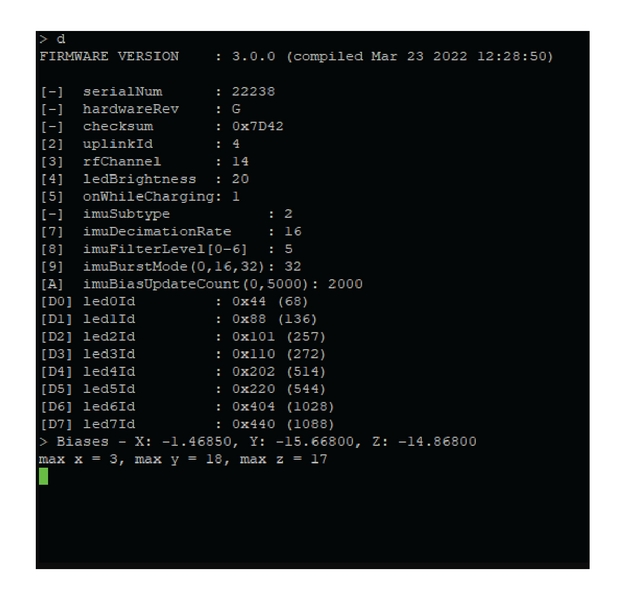
[7] imuDecimationsRate
The ADIS16505 sample rate is 2000 Hz. The decimation, dec, can is used to smooth and decrease the effective sample rate using averages. Applying the decimation rate dec yields a nominal sample rate of 2000/(dec + 1).
You should not have to change this setting.
[8] imuFilterLevel [0-6]
Default: 5
This controls the level of filtering and smoothing. 0 means no filtering, 6 means maximum filtering. We recommend level 5 as the best option.
[9] imuBurstMode
Default: 32
This setting should not be changed as this version of the firmware only supports 32-bits mode when filtering.
[A] imuBiasUpdateCount
Default: 1000
Controls the number of IMU samples between IMU bias updates. If this value is N a bias update procedure will be initiated after every N samples.
[D0] led0Id … [D7] led7Id
Default: 0x0 (0)
These settings are used to specify the active ID for each of the 8 active marker LEDs connected to the Active Tag. The default value of 0 is a special value indicating that the LED is not actively labeled and behaves as though it were a passive marker (with its LED on time synchronized with the exposure of the cameras).
The LED IDs are preprogrammed when they are sent out. The Active Batch Programmer is the best way to change these settings. Only use this setting under the guidance of an OptiTrack Support Engineer.
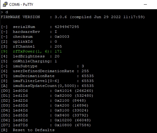
Beginning with firmware version 3.0.6, there is an additional setting that changes the radio frequency power intensity.
This setting applies to both BaseStations and Active Tags/Pucks. Below is a chart of the power that corresponds to the 1-6 range.
6
17 dBm
5
16 dBm
4
14 dBm
3
11 dBm
2
-1 dBm
1
-8 dBm
An overview of Active Tags, including power requirements, the type of Pin Out connectors used, and additional details on the IR LEDs.
The assembly of the Active Tags and the LEDs are relatively straightforward; connect the wires to the correct cathode/anode terminals using the diagrams, below.
Battery: Only use batteries that were supplied by OptiTrack.
3.3 - 5.0V inputs for micro and alternate USB connectors.
Recommended to use the LEDs that are provided directly from us.
Other LEDs must work within the following specifications: 1.5 < VLED < 2.5 and ILEDMAX = 100mA
The wires to the LEDs are 30AWG 7 gauge strands.
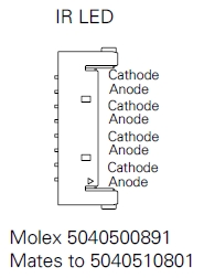
The following connectors from Molex are used on the Tags to connect the IR LEDs. Please search the corresponding part number on their website for specific information.
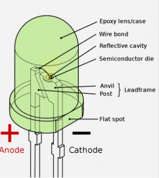
The longer leg on the LED is the cathode of this LED. As shown in the image below, The flat spot can also be referenced to indicate the cathode of this LED. Always remember this flat spot for these black LEDs, and connect the black wire (negative) when using red/black wire pairs.
The Active tag has three contact points in the bottom left corner that can be used as an alternative connection point for a power source (Battery or USB).
There is risk for short circuit when using these contact points to power the Active Tag. Please proceed with caution if using contact points to power Active Tags.
There are two methods to power the tag using contact points:
CAUTION!
Do not connect a USB cable to the board while using these pinouts. Doing so poses a risk of short-circuiting and causing damage to the board.
Connect the contact point at the top (highlighted in yellow in the image, above) to the positive terminal of a one-cell, Li-Ion 3.7v battery.
Connect the bottom left contact point (the ground, highlighted in blue, above) to the negative terminal of the battery.
Do not permanently solder the battery to the contact points as the battery cannot be charged (in any manner) while connected to the Active Tag.
Connect the bottom right contact point (highlighted in red, above) to a standard 5V USB source for power.
Connect the USB ground connection to the ground contact point (highlighted in blue, above).
CAUTION!
Do not connect a USB cable to the board while using these pinouts. Doing so poses a risk of short-circuiting and causing damage to the board.
This page provides specifications and additional information for the CinePuck.
The CinePuck is designed specifically for Virtual Production or Broadcast studios. For more information on how to use the CinePuck for Virtual Production, please visit the Virtual Production section of this documentation.
The following specifications apply for active IR LEDs on the CinePuck:
850 nm IR spectrum
8 LEDs
Illuminations synchronized with camera exposures
Illumination angle: ±60°
CinePuck Body Dimensions
Dimensions
Width: 153.30mm (~6.04”)
Length: 127.68mm(~5.03”)
Height: 25.70(~1.01”)
Weight
11.58 oz (~328.29g)
Attachment
x1 ARRI-Style Anti-Twist Mount w/ 3/8"-16 threads
x6 Standard Tripod Mounts w/ 1/4"-20 threads
Battery
2200mAh Lithium polymer battery
Charging
5V micro USB Type C
~7.5 hours* of battery life (*Battery life varies depending on frame rate and exposure settings)
5hrs zero to full charge
IMU
Dimensions
Width: 15mm
Length: 15mm
Height: 5.720mm
Weight
< 1.75g
Gyroscope
Dynamic Range
500 +/- °/sec
The number of devices with IMUs (such as CinePucks) that can attach to a BaseStation is determined by the system frame rate and the divisor applied to the BaseStation. The table below shows the IMU maximum for common frame rates with a divisor rate of 1, 2, and in some cases 3.
60
26
54
83
70
22
47
71
80
19
39
62
90
16
36
54
100
14
32
49
110
13
29
44
120
11
26
40
130
10
24
140
9
22
34
150
9
20
160
8
19
30
170
7
17
180
7
16
26
190
6
15
200
6
14
23
210
5
14
220
5
13
21
230
5
12
240
4
11
18
250
4
11
As noted, the table does not include all possible frame rate and divisor combinations. If you are familiar with using Tera Term or PuTTy, you can determine the maximum number of IMUs for any specific frame rate and divisor combination not shown on the table.
Use PuTTy to change the divisor rate on the BaseStation.
Connect an IMU puck to PuTTy.
Attempt to set the ID of the puck to an unrealistically high value. This triggers a warning that includes the current number of slots available for the given frame rate.
Set the IMU puck ID to the highest available slot for the frame rate and confirm that it appears in Motive.
BaseStations have 16 radio frequency (RF) channels available for use (11-26). When adding more than one BaseStation to a system, the IMU count is simply the maximum number of IMUs multiplied by the number of BaseStations (up to 16). For example, in a system with 4 BaseStations running at 90Hz and a divisor rate of 3, the number of allowable IMUs would be 216 (54*4=216).
To use a CinePuck in Motive, it must first be an asset. Please see the Builder pane page for instructions on creating a rigid body asset, and the page IMU Sensor Fusion for instruction on pairing the IMU.
Use the Auto-Configure feature to automatically pair and align a CinePuck to its associated IMU. When auto-configured, Motive changes the name of the Rigid Body and its associated marker constraints to CinePuck_G###.
To use a different naming convention, use the Manual Pair option instead.
Once the CinePuck rigid body is created, it will be available in the Assets pane. Select the CinePuck either in the Assets pane or the 3D Viewport to display its properties in the Properties pane.
When connected to the OptiTrack system, the properties for the CinePuck IMU and its associated BaseStation are shown in the Devices Pane. Please see the Devices Pane page for more details.
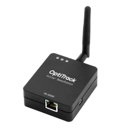
This page provides specifications for BaseStations and information about their use.
The BaseStation is the active hardware component that links other active components to Motive. Using a radio frequency channel (RF channel) between 11-26, the BaseStation synchronizes OptiTrack cameras with Active Tags and Pucks. Once the BaseStation receives the signal from the active component, it sends that data to the Motive computer along the camera network. This allows Motive to recognize Active Pucks and Tags even with significant occlusion of the LED markers, as compared to passive markers.
If you use Active Tags or Pucks, at least one BaseStation is required per tracking system.
For larger volumes, the approximate range from BaseStation to Tags/Pucks is 100’.
The number of IMUs that can attach to a BaseStation is determined by the system frame rate and the divisor applied to the BaseStation. The table below shows the IMU maximum for common frame rates with a divisor rate of 1, 2, and in some cases 3.
60
26
54
83
70
22
47
71
80
19
39
62
90
16
36
54
100
14
32
49
110
13
29
44
120
11
26
40
130
10
24
140
9
22
34
150
9
20
160
8
19
30
170
7
17
180
7
16
26
190
6
15
200
6
14
23
210
5
14
220
5
13
21
230
5
12
240
4
11
18
250
4
11
As noted, the table does not include all possible frame rate and divisor combinations. If you are familiar with using Tera Term or PuTTy, you can determine the maximum number of IMUs for any specific frame rate and divisor combination not shown on the table.
Use PuTTy to change the divisor rate on the BaseStation.
Connect an IMU puck to PuTTy.
Attempt to set the ID of the puck to an unrealistically high value. This triggers a warning that includes the current number of slots available for the given frame rate.
Set the IMU puck ID to the highest available slot for the frame rate and confirm that it appears in Motive.
BaseStations have 16 radio frequency (RF) channels available for use (11-26). When adding more than one BaseStation to a system, the IMU count is simply the maximum number of IMUs multiplied by the number of BaseStations (up to 16). For example, in a system with 4 BaseStations running at 90Hz and a divisor rate of 3, the number of allowable IMUs would be 216 (54*4=216).
As shipped, BaseStations will connect to the OptiTrack system without additional configuration by the user. Some circumstances may require a configuration update, such as when adding new BaseStations to an existing system or when you wish to change the divisor rate.
The BaseStation is configured outside of Motive, using one of the following programs:
Please see the linked pages for more details on configuring the BaseStation.
Note: Behavior of the LEDs on the BaseStation is controlled by firmware and is subject to change.
From Right to Left:
Communication Indicator LED: When the BaseStation is successfully sending data and communicating with the Active Pucks, the LED closest to the antenna will blink green. If this LED turns red, it indicates that the BaseStation failed to establish a connection with Motive.
Interference Indicator LED: The middle LED indicates if there are other signal-traffics on the respective radio channel and PAN ID that might be interfering with the active components. This LED should stay dark in order for the active marker system to work properly. If it flashes in red, consider switching both the channel and PAN ID on all of the active components.
Power Indicator LED: The LED located at the corner indicates power for the BaseStation. This LED may be disabled on BaseStations with the latest firmware, but on older BaseStations this LED may light up in red to indicate the device has power.
When connected to the OptiTrack system, the properties for any Base Station with firmware 2.x or greater and all associated active devices are shown in the Devices Pane. Please see the Devices Pane page for more details.
This feature requires BaseStation firmware version 2.x or greater. BaseStations and tags with version 1.x firmware will not be visible in the Devices pane but will still work with the OptiTrack system.
In most cases, you will not need to update the firmware on your Active components. The Active components you receive should work for your system without the need to update. In the event that you are advised to update your Active components, we strongly recommend doing so only under the guidance of a OptiTrack Support Engineer. Please contact for instructions on how to update the firmware.
When you first receive your Active Tags and BaseStation they will be on firmware 1.1.0 unless otherwise setup with your Sales Engineer for very specific applications. Firmware version 1.1.0 is recommended for most applications. These will be RevG (revision G) for Active Tags and RevD for BaseStations. These should not need to be updated. Please contact if you need assistance with your Active hardware.
If your Active hardware is older than RevG for Active Tags and RevD for BaseStations, we recommend updating to RevG and RevD respectively.
The information below is detailed information that is not intended for the average user. What you receive out of the box will work for the majority of applications based upon initial setup with a Sales Engineer.
Active components that were shipped later than September 2017 use the firmware 1.x or above.
Requires Motive 2.0 Beta 2 or later versions.
No longer requires eSync for synchronizing the BaseStation with the camera system.
Support for user-defined camera framerates.
The illumination time of active LEDs is synchronized to the camera exposure time.
Allows changing the depth of illumination patterns, allowing a higher number of active markers to be actively labeled.
Active tags with 1.x firmware and no IMU are compatible with BaseStations with 1.1.x firmware (RevA, B, C, and D BaseStations are all compatible with 1.1.x firmware)
RevA hardware version BaseStations are NOT compatible with 2.3.x firmware.
RevB, RevC, and RevD hardware version BaseStations are compatible with 2.3.x firmware.
IMU tags with 2.3.x firmware are compatible with BaseStations with 2.3.x firmware.
An IMU tag
Requires a BaseStation (RevB, RevC, RevD) with firmware 2.3.x.
Do NOT use with a BaseStation with 1.1.x firmware.
A non-IMU tag requires a BaseStation with matching firmware
IMU with 1.1.x firmware requires a BaseStation (RevA, RevB, RevC, RevD) with firmware 1.1.x.
IMU with 2.3.x firmware requires a BaseStation (RevB, RevC, RevD) with 2.3.x firmware.
Essentially, if an Active Tag has the same firmware as a BaseStation it will be compatible, with a few exceptions. For example, if you have an Active Tag with 1.x firmware and a BaseStation with 1.x firmware, they will be compatible.
CinePuck-specific firmware compatible with BaseStations with 2.3.x firmware.
Firmware Compatibility Chart
Below is a chart to see which versions are compatible with which BaseStations and Active Tags/Pucks. Essentially, it is a one-to-one correlation between Active hardware and firmware versions with some exceptions. For Active Tags specifically, it boils down to: if it doesn't have an IMU then it's compatible with 1.x. If it has the first version of an IMU, then it is compatible with 2.x. And, if it has an upgraded IMU, then it is compatible with 3.x.
These versions are outdated and no longer supported.
Active components that were shipped prior to September 2017 uses the firmware v0.8.
v0.8 BaseStation works only with v0.8 Tags.
Firmware v0.8 requires an eSync to synchronize the BaseStation and the mocap system together.
Whenever v0.8 BaseStation is power cycled, all of the v0.8 Tags must be power cycled as well.
v0.8 BaseStation is not compatible with v1.0 Tags
v0.8 Tags needs to be power cycled each time you close and relaunch Motive.
v0.8 Tags needs to be power cycled each time system frame rate has been changed in Motive.
Use the Application Settings panel to customize Motive and set default values. Application Settings can be accessed from the View menu or by clicking the icon on the main toolbar.
If the tag is unpaired, the circle x icon will appear.
If the tag is pairing, the circle with the wave icon will appear.
If the tag is paired, the green circle with green check icon will appear.
Click the in the 3D Viewport to open the Visual Aids menu.
BaseStation
BaseStation_v1.1.0_REVB
BaseStation_2.3.4
Non-IMU Tag
TAG_v1.3.2_REVG
Tag_2.3.4_nonIMU
IMU Tag
Not Compatible
Tag_2.3.3_IMU
CinePuck
Not Compatible
CinePuck_3.2.0