
Sample code with instructions on using Motive API functions to calibrate a camera system.
The following functions are used to complete the calibration process using the Motive API, and are presented in the order in which they would be performed. For details on specific functions, please refer to the Motive API: Function Reference page.
Auto-Masking
Auto-Masking is done directly using the function. When this function is called, Motive will sample for a short amount of time and apply a mask to the camera imagers where light was detected.
Camera Mask
The function returns the memory block of the mask, with one bit per each pixel of the mask. Masking pixels are rasterized from left to right and from top to bottom of the camera's view.
Clear Masks
The function is used to clear existing masks from the 2D camera view. It returns true when it successfully removes pixel masks.
Set Camera Mask
The function is used to replace the existing camera mask for any camera. A mask is an array of bytes, one byte per mask pixel block. Returns true when masks are applied.
The function is used to report the current state and is typically tracked throughout the calibration process. In addition to providing status information to the operator, the Calibration state is used to determine if and when other calibration functions should be run.
OptiTrack Calibration Wands are configured with preset distances between the markers to ensure precision when calculating the position of the marker in the 3D space. For this reason, it's critical to use the SetCalibrationWand function to establish the correct wand type prior to collecting samples.
The Wand Type is identified as follows:
The function begins the calibration wanding process, collecting samples until the function is called.
The function shows which cameras need more samples to obtain the best calibration. When this function returns an empty vector, then there are sufficient samples to begin calculating the calibration.
The function ends the wanding phase and begins calculating the calibration from the samples collected.
Use the function to monitor progress through the following states:
Initialized: the calibration process has started.
Wanding: the system is collecting samples.
WandingComplete: the system has finished collecting samples. This state is set automatically when the function is called.
PreparingSolver: the system is setting up the environment for the solver.
Once the Calibration State is "Phase4," use the function to apply the newly calculated calibration to the cameras.
The function stops the calibration process. Use this when a calibration error occurs or any other time you wish to stop the calibrating.
Use the function to score the calibration quality on a scale from 0-5, with 5 being the highest quality.
Set the ground plane by calling the function. When called, the camera system will search for 3-markers that resemble a calibration square. Once found, the system will use the inputted vertical offset value to configure the ground plane.
EstimatingFocals: the system is estimating the camera focal lengths.
CalculatingInitial: the system is setting up the environment to calculate the calibration.
Phase1 - 3: the system is calculating the calibration.
Phase4: the calibration calculation is finished and ready for the user to either apply or cancel.
Complete: the calibration has been applied to the cameras and the process is finished.
CalibrationError: this state occurs either when the calibration has not been started (or reset) or when an error occurs during the calibration process.
WandLarge
CW-500 (500mm)
WandStandard
Legacy (400mm)
WandSmall
CW-250 (250mm)
WandCustom
Custom Wand
WandMicron
Micron Series
An introduction to the Motive API.
Important Note:
The Motive API documentation is being updated for 3.1 and some of the functions may not yet be in the documentation. Please refer to the MotiveAPI header file for any information that is not included in the online user guide.
The Motive API allows access to and control of the backend software platform for Motive via a C/C++ interface, performing Motive functions without the graphical user interface on top. With the API, users can employ several features of Motive in custom applications, such as accessing 2D camera images, marker centroid data, unlabeled 3D points, labeled markers, and Rigid Body tracking data.
All of the required components for utilizing the API are included in the Motive install directory when the application is installed. The key files for using the Motive API are listed in the below section.
Camera control
Frame control
Point Cloud reconstruction engine control
Ability to obtain and use reconstructed 3D Marker data
In-depth hardware control (e.g. hardware sync customization). Use the Camera SDK for this.
Direct support for data recording and playback.
Control over peripheral devices (Force plates and NI-DAQ).
Functionality for Skeleton assets.
The Motive API is supported in Windows only
Must have a valid Motive license and a corresponding Hardware or Security key.
When Motive is installed, all of the required components of the Motive API are placed in folders within the installation directory. By default, this directory is C:\Program Files\OptiTrack\Motive.
The following section describes the key files of the API and where each is located.
[Motive Install Directory]\inc\MotiveAPI.h
The header file MotiveAPI.h contains declarations for functions and classes of the API. Necessary functions and classes are thoroughly commented within this file. This header file must be included in the source code for utilizing the Motive API functions.
[Motive Install Directory]\lib
This folder includes C++ 64-bit library files (.lib and .dll) for employing the Motive API.
[Motive Install Directory]\Samples\MotiveAPI\
Samples in a Visual Studio project (samples.sln) for accessing Motive functionality such as cameras, markers, and Rigid Body tracking information. Refer to this folder to find out how the API can be used.
[Motive Install Directory]\plugins
The platforms folder contains qwindows.dll, which is required for running applications using the Motive API. Copy and paste this folder into the EXE directory.
[Motive Install Directory]
Third-party DLL libraries are required for all applications built against the API. Please see for more information.
This guide introduces some of the commonly used functions of the Motive API.
A reference guide for Motive API functions, including code samples.
Many of the Motive API functions return their results as integer values defined as an eResult. This value expresses the outcome of the result. eResult values indicate if the function operated successfully, and if not, they provide detailed information on the type of error that occurred.
When you get the eResult output from a function, you can use the MapToResultString function to get the plain text result that corresponds to the error message.
Camera video types, or image processing modes, are expressed as integer values as well. These values are listed below and are also commented within the header file.
eResult Values
Camera Video Type Definitions
Rigid body tracking
Query results
Ability to stream results over the network
MOTIVE_API const std::wstring MapToResultString( eResult result ); // Returns text of detail information on the result.enum eResult
{
kApiResult_Success = 0,
kApiResult_Failed,
kApiResult_FileNotFound,
kApiResult_LoadFailed,
kApiResult_SaveFailed,
kApiResult_InvalidFile,
kApiResult_InvalidLicense,
kApiResult_NoFrameAvailable,
kApiResult_TooFewMarkers,
kApiResult_ToManyMarkers,
kApiResult_UnableToFindGroundPlane,
kApiResult_UnableGetGroundPlane,
kApiResult_RemoveCalibrationSquare
};enum eVideoType
{
kVideoType_Segment = 0,
kVideoType_Grayscale = 1,
kVideoType_Object = 2,
kVideoType_Precision = 4,
kVideoType_MJPEG = 6,
kVideoType_ColorH264 = 9
};An overview of the Motive API.
SDK/API Support Disclaimer
OptiTrack provides developer tools to enable our customers across a broad set of applications to utilize their systems in the ways that best suit them. Our Motive API through the NatNet SDK and Camera SDK is designed to enable experienced software developers to integrate data transfer and/or system operation with their preferred systems and pipelines. Sample projects are provided with each tool, and we strongly recommend users reference or use the samples as reliable starting points.
The following list specifies the range of support OptiTrack provides for the SDK and API tools:
Using the SDK/API tools requires background knowledge of software development. We do not provide support for basic project setup, compiling, and linking when using the SDK/API to create your own applications.
We ensure the SDK tools and their libraries work as intended. We do not provide support for custom developed applications that have been programmed or modified by users using the SDK tools.
Ticketed support will be provided for licensed Motive users using the Motive API and/or the NatNet SDK tools from the included libraries and sample source codes only.
This guide provides detailed instructions for commonly used functions of the Motive API for developing custom applications. For a full list of functions, refer to the page. For a sample use case of the API functions, please check out the provided project.
In this guide, the following topics will be covered:
Library files and header files
Initialization and shutdown
Capture setup (Calibration)
Configuring camera settings
When developing a Motive API project, the linker needs to know where to find the required library files. Do this either by specifying its location within the project or by copying these files to the project folder.
MotiveAPI.h
Motive API libraries (.lib and .dll) are in the lib folder within the Motive install directory, located by default at C:\Program Files\OptiTrack\Motive\lib. This folder contains library files for both 64-bit (MotiveAPI.dll and MotiveAPI.lib) platforms.
When using the API library, all of the required DLL files must be located in the executable directory. If necessary, copy and paste the MotiveAPI.dll file into the folder with the executable file.
Third-party Libraries
Additional third-party libraries are required for Motive API, and most of the DLL files for these libraries can be found in the Motive install directory C:\Program Files\OptiTrack\Motive\. Copy and paste all of the DLL files from the Motive installation directory into the directory of the Motive API project to use them. Highlighted items in the below image are all required DLL files.
Lastly, copy the C:\Program Files\OptiTrack\Motive\plugins\platforms folder and its contents into the EXE folder since those libraries will also be used.
Function declarations and classes are contained in the header file MotiveAPI.h, located in the folder C:\Program Files\OptiTrack\Motive\inc\.
Always include the directive syntax for adding the MotiveAPI.h header file for all programs that are developed against the Motive API.
Note: You can define this directory by using the MOTIVEAPI_INC, MOTIVEAPI_LIB environment variables. Check the project properties (Visual Studio) of the provided project for a sample project configuration.
Motive API, by default, loads the default calibration (CAL) and Application profile (MOTIVE) files from the program data directory unless otherwise specified. Motive also loads these files at startup. They are located in the following folders:
Default System Calibration: C:\ProgramData\OptiTrack\Motive\System Calibration.cal
Default Application Profile: C:\ProgramData\OptiTrack\MotiveProfile.motive
Both files can be exported and imported into Motive as needed for the project:
The can be imported using the function to obtain software settings and trackable asset definitions.
The Calibration file can be imported using the function to ensure reliable 3D tracking data is obtained.
When using the API, connected devices and the Motive API library need to be properly initialized at the beginning of a program and closed down at the end.
To initialize all of the connected cameras, call the function. This function initializes the API library and gets the cameras ready to capture data, so always call this function at the beginning of a program. If you attempt to use the API functions without initializing first, you will get an error.
The function is primarily used for updating captured frames, but it can also be called to update a list of connected devices. Call this function after initialization to make sure all of the newly connected devices are properly initialized in the beginning.
When exiting out of a program, call the function to completely release and close all connected devices. Cameras may fail to shut down completely if this function is not called.
The Motive application profile (MOTIVE) stores the following critical information:
All the trackable assets involved in a capture;
Software configurations including and .
When using the API, we recommend first configuring settings and defining the trackable assets in Motive, then exporting the profile MOTIVE file, to load by calling the function. This allows you to adjust the settings for your needs in advance without having to configure individual settings through the API.
Cameras must be calibrated to track in 3D space. Because camera calibration is a complex process, it's easier to calibrate the camera system from Motive, export the camera calibration file (CAL), then load the exported file into custom applications that are developed against the API.
Once the calibration data is loaded, the 3D tracking functions can be used. For detailed instructions on camera calibration in Motive, please read through the page.
Loading Calibration
In Motive, calibrate the camera system using the Calibration pane. Follow the page for details.
After the system has been calibrated, export the calibration file (CAL) from the Motive file menu.
Using the API, Import the calibration to your custom application by calling the function.
When successfully loaded, you will be able to obtain 3D tracking data using the API functions.
Connected cameras are accessible by index numbers, which are assigned in the order the cameras are initialized. Most API functions for controlling cameras require the camera's index value.
When processing all of the cameras, use the function to obtain the total camera count and process each camera within a loop. To point to a specific camera, use the function to check and use the camera with its given index value.
This section covers Motive API functions to check and configure camera frame rate, camera video type, camera exposure, pixel brightness threshold, and IR illumination intensity.
Camera settings are also located in the Devices pane of Motive. For more information on each of these camera settings, refer to the page.
Use the SetCameraProperty function to configure properties outlined below.
There are other camera settings, such as imager gain, that can be configured using the Motive API. Please refer to the page for descriptions on other functions.
To process multiple consecutive frames, call the functions or repeatedly within a loop. In the example below, the Update function is called within a while loop as the frameCounter variable is incremented:
At the most fundamental level, these two functions both update the incoming camera frames, but may act differently in certain situations. When a client application stalls momentarily, it can get behind on updating the frames and the unprocessed frames may accumulate. In this situation, these two functions behave differently.
The function disregards accumulated frames and services only the most recent frame data. The client application will not receive the previously missed frames to process.
The function ensures only one frame is processed each time the function is called. If there are significant stalls in the program, using this function may result in accumulated processing latency.
In general, we recommend using the Update function. Only use UpdateSingleFrame in the case when you need to ensure the client application has access to every frame of tracking data and you are not able to call Update in a timely fashion.
After loading a valid , you can use API functions to track retroreflective markers and get their 3D coordinates. Since marker data is obtained for each frame, always call the or the function each time newly captured frames are received.
You can use the function to obtain the total marker count and use this value within a loop to process all of the reconstructed markers.
Marker Index
In a given frame, each reconstructed marker is assigned a marker index number, which is used to point to a particular reconstruction within a frame. Marker index values may vary between different frames, but unique identifiers always remain the same.
Marker Position
For obtaining 3D position of a reconstructed marker, use the MarkerXYZ function.
This section covers functions for tracking Rigid Bodies using the Motive API.
To track the 6 degrees of freedom (DoF) movement of a (presumably) undeformable object, attach a set of reflective markers to it and use the markers to create a trackable Rigid Body asset.
There are two methods for obtaining Rigid Body assets when using the Motive API:
Import existing Rigid Body data.
Define new Rigid Bodies using the function.
Once Rigid Body assets are defined, Rigid Body tracking functions can be used to obtain the 6 DoF tracking data.
Let's go through importing RB assets into a client application using the API. In Motive, Rigid Body assets can be created from three or more reconstructed markers, and all of the created assets can be exported out into either application profile (MOTIVE) Each Rigid Body asset saves marker arrangements when it was first created. As long as the marker locations remain the same, you can use saved asset definitions for tracking respective objects.
Exporting all RB assets from Motive:
Exporting application profile: File → Save Profile
Exporting individual RB asset:
Exporting Rigid Body file (profile): Under the , right-click on a RB asset and click Export Rigid Body
When using the API, you can load exported assets by calling the function for application profiles and the or function. When importing profiles, the LoadRigidBodies function will entirely replace the existing Rigid Bodies with the list of assets from the loaded profile. On the other hand, AddRigidBodes will add the loaded assets onto the existing list while keeping the existing assets. Once Rigid Body assets are imported into the application, the API functions can be used to configure and access the Rigid Body assets.
Rigid body assets can be defined directly using the API. The CreateRigidBody function defines a new Rigid Body from given 3D coordinates. This function takes in an array float values which represent x/y/z coordinates or multiple markers in respect to Rigid Body pivot point. The float array for multiple markers should be listed as following: {x1, y1, z1, x2, y2, z2, …, xN, yN, zN}. You can manually enter the coordinate values or use the MarkerXYZ function to input 3D coordinates of tracked markers.
When using the MarkerXYZ function, you need to keep in mind that these locations are taken in respect to the RB pivot point. To set the pivot point at the center of created Rigid Body, you will need to first compute pivot point location, and subtract its coordinates from the 3D coordinates of the markers obtained by the MarkerXYZ function. This process is shown in the following example.
Example: Creating RB Assets
6 DoF Rigid Body tracking data can be obtained using the RigidBodyTransform function. Using this function, you can save 3D position and orientation of a Rigid Body into declared variables. The saved position values indicate location of the Rigid Body pivot point, and they are represented in respect to the global coordinate axis. The Orientation is saved in both Euler and Quaternion orientation representations.
Example: RB Tracking Data
In Motive, Rigid Body assets have assigned to each of them. Depending on how these properties are configured, display and tracking behavior of corresponding Rigid Bodies may vary.
For detailed information on individual Rigid Body settings, read through the page.
Once the API is successfully initialized, there are two methods of data streaming available.
The function enables/disables data streaming via the . This client/server networking SDK is designed for sending and receiving OptiTrack data across networks, and can be used to stream tracking data from the API to client applications from various platforms.
Once the data streaming is enabled, connect the NatNet client application to the server IP address to start receiving the data.
The StreamNP function is equivalent to Broadcast Frame Data from the pane in Motive.
Mocap data can be livestreamed through the Virtual Reality Peripheral Network (VRPN) using the function.
The Motive API does not support data streaming configuration directly from the API. These properties must be set in Motive.
In Motive, configure the streaming server IP address and other data streaming settings. See the page for more information.
Export the Motive profile (MOTIVE file) that contains the desired configuration.
Load the exported profile through the API.
The Camera SDK is a free product. We do not provide free ticketed support for it.
For other questions, please check out the NaturalPoint forums. Very often, similar development issues are reported and solved there.
Updating captured frames
3D marker tracking
Rigid body tracking
Data streaming
Precision
4
MJPEG
6
Color Video
9
Corresponds to the Video Mode setting in Motive's Camera Properties.
Please see the Camera Video Types page for more information on video modes.
High Quality
3
Corresponds to the MJPEG Quality setting in Motive's Camera Properties.
Segment
0
Grayscale
1
Object
Minimum Quality
0
Low Quality
1
Standard Quality
2
2
// Initializing all connected cameras
Initialize();// Initializing all connected cameras
Initialize();
//Update for newly arrived cameras
Update();// Closing down all of the connected cameras
Shutdown();
return 0;LoadProfile("UserProfile.motive"); // Loading application profile, UserProfile.motiveLoadCalibration("CameraCal.cal"); // Loading CAL fileCameraProperty( int cameraIndex, const std::wstring& propertyName );SetCameraProperty( int cameraIndex, const std::wstring& propertyName, const sPropertyValue& value );/// <item><description>CameraNodeFirmwareVersion (std::wstring)</description></item>/// <item><description>CameraNodeLogicVersion (std::wstring)</description></item>int main()
{
Initialize();
int frameCounter = 0; // Frame counter variable
while (!_kbhit())
{
if(Update() == eRESULT_SUCCESS)
{
// Each time the Update function successfully updates the frame,
// the frame counter is incremented, and the new frame is processed.
frameCounter++;
////// PROCESS NEW FRAME //////
}
}
}Update() // Process all outstanding frames of data.
UpdateSingleFrame() // Process one outstanding frame of data.int totalMarker = MarkerCount();
printf("Frame #%d: (Markers: %d)\n", framecounter, totalMarker);
int x = 0;
int y = 0;
int z = 0;
//== Use a loop to access every marker in the frame ==//
for (int i = 0 ; i < totalMarker; i++) {
MarkerXYZ(i,x,y,z);
printf("\tMarker #%d:\t(%.2f,\t%.2f,\t%.2f)\n\n",
i, x, y, z);
}LoadProfile("UserProfile.motive"); // Loading application profileLoadRigidBodies("asset1.motive"); // Replaces RBs with RBs from "asset1.motive" AddRigidBodies("asset1.motive"); // Adds RBs from file to already existing RBs
SaveRigidBodies("asset1.motive"); // Saves RBs from RB list to fileCreateRigidBody(const wchar_t* name, int id, int markerCount, float* markerList);int markerCount = MarkerCount;
vector<float> markerListRelativeToGlobal(3*markerCount);
// add markers to markerListRelativeToGlobal using MarkerXYZ, etc
int x = 0;
int y = 0;
int z = 0;
for (int i = 0; i < markerCount; ++i)
{
MarkerXYZ(i, x, y, z);
markerListRelativeToGlobal.push_back(x);
markerListRelativeToGlobal.push_back(y);
markerListRelativeToGlobal.push_back(z);
}
// then average the locations in x, y and z
for (int i = 0; i < markerCount; ++i)
{
float sx += markerListRelativeToGlobal[3*i];
float sy += markerListRelativeToGlobal[3*i + 1];
float sz += markerListRelativeToGlobal[3*i + 2];
}
float ax = sx/markerCount;
float ay = sy/markerCount;
float az = sz/markerCount;
vector<float> pivotPoint = {ax, ay, az};
vector<float> markerListRelativeToPivotPoint(3*markerCount);
// subtract the pivot point location from the marker location
for (int i = 0; i < markerCount; ++i)
{
markerListRelativeToPivotPoint.push_back(markerListRelativeToGlobal[3*i] - ax);
markerListRelativeToPivotPoint.push_back(markerListRelativeToGlobal[3*i + 1] - ay);
markerListRelativeToPivotPoint.push_back(markerListRelativeToGlobal[3*i + 2] - az);
}
CreateRigidBody("Rigid Body New", 1, markerCount, markerListRelativeToPivotPoint);RigidBodyTransform(int rbIndex, //== RigidBody Index
float *x, float *y, float *z, //== Position
float *qx, float *qy, float *qz, float *qw, //== Quaternion
float *yaw, float *pitch, float *roll); //== Euler//== Declared variables ==//
float x, y, z;
float qx, qy, qz, qw;
float yaw, pitch, roll;
int rbcount = RigidBodyCount();
for(int i = 0; i < rbcount; i++)
{
//== Obtaining/Saving the Rigid Body position and orientation ==//
RigidBodyTransform( i, &x, &y, &z, &qx, & qy, &qz, &qw, &yaw, &pitch, &roll );
if( IsRigidBodyTracked( i ) )
{
wchar_t name[ 256 ];
RigidBodyName( i, name, 256 );
wprintf( L"\n%s: Pos (%.3f, %.3f, %.3f) Orient (%.1f, %.1f, %.1f)\n", name, x, y, z, yaw, pitch, roll );
}
}RigidBodyProperty(int rbIndex, const std::wstring& propertyName);SetRigidBodyProperty(int rbIndex, const std::wstring& propertyName, const sPropertyValue& value); /// <list type="bullet">
///<item><description> NodeName (String) </description></item>
///<item><description> AssetName (String) </description></item>
///<item><description> GeometryYawPitchRoll (eVector3f) </description></item>
///<item><description> BoneMajorAxis (Int) </description></item>
///<item><description> DefaultBoneLength (double) </description></item>
///<item><description> DefaultBoneDiameter (double) </description></item>
///<item><description> JointName (String) </description></item>
///<item><description> ParentInfo (String) </description></item>
///<item><description> ChildInfo (String) </description></item>
///<item><description> JointVisible (Bool) </description></item>
///<item><description> JointType (String) </description></item>
///<item><description> DegreesOfFreedom (Int) </description></item>
///<item><description> RotationOrder (Int) </description></item>
///<item><description> RotationOffset (eRotationf) </description></item>
///<item><description> TranslationOffset (eVector3f) </description></item>
///<item><description> TipOffset (eVector3f) </description></item>
///<item><description> AssetVisible (Bool) </description></item>
///<item><description> Comment (String) </description></item>
///<item><description> MinimumBootingLabels (Int) </description></item>
///<item><description> MinimumMarkerCount (Int) </description></item>
///<item><description> MinimumBootingActive (Int) </description></item>
///<item><description> Scale (double) </description></item>
///<item><description> SyntheticLabelGraphScale (double) </description></item>
///<item><description> ShowLabel (Bool) </description></item>
///<item><description> ShowIMUState (Int) </description></item>
///<item><description> DisplayTracked (Bool) </description></item>
///<item><description> Color (Int) </description></item>
///<item><description> ShowBones (Bool) </description></item>
///<item><description> BoneColor (Int) </description></item>
///<item><description> ShowAxis (Bool) </description></item>
///<item><description> DisplayPositionHistory (Bool) </description></item>
///<item><description> DisplayHistoryLength (Int) </description></item>
///<item><description> ShowDOF (Bool) </description></item>
///<item><description> ShowMarkerSet (Bool) </description></item>
///<item><description> ShowTargetMarkerLines (Bool) </description></item>
///<item><description> ShowMarkerLines (Bool) </description></item>
///<item><description> Smoothing (double) </description></item>
///<item><description> PredictionTime (double) </description></item>
///<item><description> PositionDamping (eVector3f) </description></item>
///<item><description> RotationDamping (double) </description></item>
///<item><description> RotationDampingAxis (Int) </description></item>
///<item><description> ModelAlpha (double) </description></item>
///<item><description> GeometryType (Int) </description></item>
///<item><description> GeometryFile (String) </description></item>
///<item><description> GeometryScale (eVector3f) </description></item>
///<item><description> GeometryOffset (eVector3f) </description></item>
///<item><description> GeometryPitchYawRoll (eVector3f) </description></item>
///<item><description> Name (String) </description></item>
///<item><description> UserData (Int) </description></item>
///<item><description> ActiveTagID (Int) </description></item>
///<item><description> ActiveTagRfChannel (Int) </description></item>
///<item><description> TrackingAlgorithmLevel (Int) </description></item>
///<item><description> ShareMarkers (Bool) </description></item>
///<item><description> MarkerID (Int) </description></item>
///<item><description> MarkerLocation (eVector3f) </description></item>StreamNP(true); //Enabling NatNet Streaming.StreamVRPN(true); //Enabling VRPN Streaming.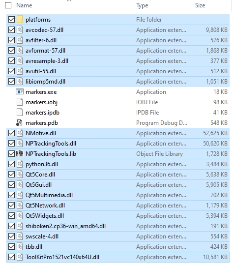
A guide to the functions available in the Motive API.
Please use the table of contents to the right to navigate to categories of functions. Links to the specific functions in each category are contained in the section header.
Alternately, use Ctrl + F to search the page contents.
Important Note:
Some functions are not yet included in the documentation. Please refer to the Motive API header file (MotiveAPI.h) for information on any functions that are not documented here.
In this section:
| | | |
In this section:
|
In this section:
| |
In this section:
| | | | | | | | | | | | | | |
In this section:
|
In this section:
| |
In this section:
| | | | | | | |
In this section:
| | | | | | | | | | | | | | | | | | | | | | | |
In this section:
| | | | | | | |
Initiates the Rigid Body refinement process. Input the number of samples and the ID of the Rigid Body you wish to refine. After starting the process, RigidBodyRefineSample must be called on every frame to collect samples.
Description
This function is used to start Rigid Body refinement.
Function Input
Target Rigid Body ID
Sample count (int)
Function Output
Returns true if the refinement process has successfully initiated.
This function collects samples for Rigid Body refinement after calling the RigidBodyRefineStart function. Call this function for every frame within the update loop. You can check the progress of calibration by calling the RigidBodyRefineProgress function.
Description
This function collects Rigid Body tracking data for refining the definition of the corresponding Rigid Body.
Function Input
None. Samples frames for the initialized refine progress.
Function Output
Returns true if the refinement process has successfully collected a sample. This function does not collect samples if the Rigid Body is not tracked on the frame.
This function inquiries the state of the refinement process. It returns eRigidBodyRefineState enum as a result.
Description
This function queries the state of the Rigid Body refinement process. It returns an enum value for indicating whether the process is initialized, sampling, solving, complete, or uninitialized.
Function Input
None. Checks the state on the ongoing refinement process.
Function Output
Returns eRigidBodyRefineState enum value.
This function retrieves the overall sampling progress of the rigid body refinement solver.
Description
When the refinement process is under the sampling state, calling this function returns the sampling progress. It will return a percentage value representing the sampling progress with respect to the total number of samples given in the RigidBodyRefineStart parameter.
Function Input
None. Checks the progress on the ongoing refinement process.
Function Output
Returns percentage completeness of the sampling process (float).
This function returns the error value of the Rigid Body definition before the refinement and is typically called in conjunction with RigidBodyRefineResultError.
Description
Once the refinement process has reached complete stage, this function can be called along with RigidBodyRefineResultError to compare the error values from the corresponding Rigid Body definition before and after the refinement.
Function Input
None.
Function Output
Average error value of the target Rigid Body definition prior (RigidBodyRefineInitialError) and after (RigidBodyRefineResultError) the refinement.
This function returns the error value of the Rigid Body definition after the refinement.
Description
Once the refinement process has reached complete stage, this function can be called along with RigidBodyRefineInitialError to compare the error values from the corresponding Rigid Body definition before and after the refinement.
Function Input
None.
Function Output
Average error value of the target Rigid Body definition prior (RigidBodyRefineInitialError) and after (RigidBodyRefineResultError) the refinement.
This function applies the refined result to the corresponding Rigid Body definition.
Description
This function applies the refinement to the Rigid Body definition. Call this function after comparing the error values before and after the refinement using the RigidBodyRefineInitialError and RigidBodyRefineResultError functions.
Function Input
None.
Function Output
Returns true if the refined results have been successfully applied.
This function discards the final refinement result and resets the refinement process.
Description
If the final refinement result from the RigidBodyRefineResultError call is not satisfying, you can call this function to discard the result and start over from the sampling process again.
Function Input
None.
Function Output
Returns true if the refined results have been successfully reset.
In this section:
| | | | | | |
Returns the total number of cameras connected to the system.
Description
This function returns a total camera count.
Function Input
None
Function Output
Total number of cameras (int)
C++ Example
Returns the camera group count.
Description
This function returns the total count of camera groups that are involved in the project.
This will generally return a value of two: one for the tracking cameras and one for reference cameras.
Function Input
None
Function Output
Camera group count (int)
C++ Example
Returns an index value of a camera group that a camera is in.
Description
This function takes an index value of a camera and returns the corresponding camera group index that the camera is in.
Function Input
Camera index (int)
Function Output
Camera group index (int)
C++ Example
Returns the corresponding camera's serial number as an integer.
Description
This function returns the corresponding camera's serial number.
Function Input
Camera index (int)
Function Output
Camera serial number (int)
C++ Example
Returns a total number of objects detected by a camera in the current frame.
Description
This function returns a total number of centroids detected by a camera.
A centroid is defined for every group of contiguous pixels that forms a shape that encloses the thresholded pixels.
The size and roundness filter (cCameraGroupFilterSettings) is not applied in this data.
Function Input
Camera index (int)
Function Output
Number of centroids (int)
C++ Example
Returns 2D location of the centroid as seen by a camera.
Description
This function saves 2D location of the centroid as detected by a camera's imager.
Returns true if the function successfully saves the x and y locations.
Function Input
Camera index (int)
Object index (int)
Declared variables for saving x and y (float)
Function Output
True/False (bool)
C++ Example
Retrieve the pre-distorted object location in the view of the camera.
Description
This function saves the predistorted 2D location of a centroid.
This data indicates where the camera would see a marker if there were no effects from lens distortions. For most of our cameras/lenses, this location is only a few pixels different from the distorted position obtained by the CameraObject function.
Returns true when the values are successfully saved.
Function Input
Camera index (int)
Object (centroid) index (int)
Declared variable for saving x location (float)
Declared variable for saving y location (float)
Function Output
True/False (bool)
C++ Example
Configures the value of a camera property.
Description
This function sets camera properties for a camera device specified by its index number.
A false return value indicates the function did not complete the task.
Each of the video types is indicated with the following integers. Supported video types may vary for different camera models. Please check the Data Recording page for more information on which image processing modes are available in different models.
Function Input
Camera index (int)
Name of the propety to set (const std::wstring&)
For more information on the camera settings, refer to the Devices pane page.
Function Output
True/False (bool)
In this section:
| | | | | | |
Sets frame rate decimation ratio for processing grayscale images.
Description
This feature is available only in Flex 3 and Trio/Duo tracking bars, and has been deprecated for other camera models.
This functions sets the frame decimation ratio for processing grayscale images in a camera.
Depending on the decimation ratio, a fewer number of grayscale frames will be captured. This can be beneficial when looking to reduce the processing loads.
Supported decimation ratios: 0, 2, 4, 6, 8. When the decimation setting is set to 4, for example, a camera will capture one grayscale frame for 4 frames of the tracking data.
Function Input
Camera index (int)
Decimation value (int)
Function Output
True/False (bool)
C++ Example
Retrieves the configured grayscale image frame rate decimation ratio of a camera.
Description
This feature is available only in Flex 3 and Trio/Duo tracking bars, and it has been deprecated for other camera models.
This function returns grayscale frame rate decimation ratio of a camera.
Valid decimation ratios are 0, 2, 4, 8. When the decimation setting is set to 4, for example, a camera will capture one grayscale frame for 4 frames of the tracking data.
To set the decimation ratio, use the function.
Function Input
Camera index (int)
Function Output
Decimation ratio (int)
C++ Example
Checks if the continuous IR mode is supported.
Description
This function checks whether the continuous IR illumination mode is available in the camera model.
In the continuous IR mode, the IR LEDs will not strobe but will illuminate continuously instead.
Continuous IR modes are available only in the Flex 3 camera model and the Duo/Trio tracking bars.
Returns true if continuous IR mode is available.
Function Input
Camera index (int)
Function Output
True / False (bool)
C++ Example
Enables or disables continuous IR, if the camera supports it.
Description
This function enables, or disables, continuous IR illumination in a camera.
Continuous IR mode outputs less light when compared to Strobed (non-continuous) illumination, but this mode could be beneficial in situations where there are extraneous IR reflections in the volume.
Use the CameraIsContinuousIRAvailable function to check if the camera supports this mode.
Function Input
Camera index (int)
A Boolean argument for enabling (true) or disabling (false)
Function Output
True / False (bool)
C++ Example
Checks if the continuous IR mode is enabled.
Description
This function checks if the continuous IR mode is enabled or disabled in a camera.
Returns true if the continuous IR mode is already enabled.
Function Input
Camera index (int)
Function Output
True / False (bool)
C++ Example
Sets the camera frame rate.
Description
This function sets the master frame rate for the camera system.
Returns true if it successfully adjusts the settings.
Note that this function may assign a frame rate setting that is out of the supported range. Check to make sure the desired frame rates are supported.
Function Input
Frame rate (frames/sec)
Function Output
True/False (bool).
C++ Example
Retrieves the the current master system frame rate.
Description
This function returns the master frame rate of a camera system.
Function Input
none
Function Output
Camera frame rate (int)
C++ Example
In this section:
| | | |
Measures the image board temperature of a camera.
Description
This function returns the temperature (in Celsius) of a camera's image board.
Temperature sensors are featured only in Prime series camera models.
Function Input
Camera index (int)
Function Output
Image board temperature (float)
C++ Example
Measures the IR LED board temperature of a camera.
Description
This function returns temperature (in celsius) of a camera's IR LED board.
Temperature sensors are featured only in Prime series camera models.
Function Input
Camera index (int)
Function Output
IR LED board temperature (float)
C++ Example
Enables or disables automatic gain control.
Description
This function enables or disables automatic gain control (AGC).
Automatic Gain Control feature adjusts the camera gain level automatically for best tracking.
AGC is only available in Flex 3 cameras and Duo/Trio tracking bars.
Returns true when the operation completed successfully.
Function Input
Camera index (int)
Enabled (true) / disabled (false) status (bool)
Function Output
True/False (bool)
C++ Example
Enables or disables automatic exposure control.
Description
This function enables or disables Automatic Exposure Control (AEC) for featured camera models.
This feature is only available in Flex 3 cameras and Duo/Trio tracking bars.
AEC allows a camera to automatically adjust its exposure setting by looking at the properties of the incoming frames.
Returns true if the operation was successful.
Function Input
Camera index (int)
A Boolean argument for enabling (true) or disabling (false) the filter.
Function Output
True/false (bool)
C++ Example
Retrieves the total number of gain levels available in a camera.
Description
This function returns a total number of available gain levels in a camera.
Different camera models may have different gain level settings. This function can be used to check the number of available gain levels.
Function Input
Camera index (int)
Function Output
Number of gain levels available (int)
C++ Example
In this section:
| | | | | | | | | | | | | | |
Clears masking from camera's 2D view.
Description
This function clears existing masks from the 2D camera view.
Returns true when it successfully removes pixel masks.
Function Input
Camera index (int)
Function Output
True / False (bool)
C++ Example
Description
This function allows a user-defined image mask to be applied to a camera.
A mask is an array of bytes, one byte per mask pixel block.
Returns true when masks are applied.
Function Input
Camera index (int)
Buffer
BufferSize
Function Output
True / False (bool)
C++ Example
Description
This function returns the memory block of the mask.
One bit per a pixel of the mask.
Masking pixels are rasterized from left to right and from top to bottom of the camera's view.
Function Input
Camera index (int)
Buffer
Buffer size
Function Output
True / False (bool)
C++ Example
Description
This function retrieves the width, height, and grid size of the mask for the camera at the given index.
One byte per pixel of the mask. Masking width * masking height gives the required size of the buffer.
Returns true when the information is successfully obtained and saved.
Function Input
Camera index (int)
Declared variables:
Masking width (int)
Masking height (int)
Function Output
True / False (bool)
C++ Example
Auto-mask all cameras with additional masking data.
Description
Auto-mask all cameras.
This is additive to any existing masking.
To clear masks on a camera, call ClearCameraMask prior to auto-masking.
Function Input
none
Function Output
Auto masks all cameras
Sets the state for a camera.
Description
This function configures the camera state of a camera. Different camera states are defined in the eCameraState enumeration.
Returns true when it successfully sets the camera state.
Function Input
Camera index (int)
Camera state (eCameraState)
Function Output
True / False (bool)
C++ Example
Retrieves the current participation state of a camera.
Description
This function obtains and saves the camera state of a camera onto the declared variables.
Returns true if it successfully saves configured state.
Function Input
Camera index (int)
Declared variable for camera state (eCameraState)
Function Output
True / False (bool)
C++ Example
Returns the Camera ID.
Description
This function takes in a camera index number and returns the camera ID number.
Camera ID numbers are the numbers that are displayed on the devices.
The Camera ID number is different from the camera index number.
On Prime camera systems, Camera IDs are assigned depending on where the cameras are positioned within the calibrated volume.
Function Input
Camera index (int)
Function Output
Camera ID (int)
C++ Example
Fills a buffer with images from camera's view.
Description
This function fetches raw pixels from a single frame of a camera and fills the provided memory block with the frame buffer.
The resulting image depends on which video mode the camera is in. For example, if the camera is in grayscale mode, a grayscale image will be saved from this function call.
For obtaining buffer pixel width and height, you can use the CameraNodeImagerPixelSize property to obtain respective camera resolution.
Function Input
Camera index (int)
Buffer pixel width (int)
Buffer pixel height (int)
Buffer byte span (int)
Function Output
True / False (bool)
C++ Example
Saves image buffer of a camera into a BMP file.
Description
This function saves image frame buffer of a camera into a BMP file.
Video type of the saved image depends on configured camera settings
Attaches *.bmp at the end of the filename.
Returns true if it successfully saves the file.
Function Input
Camera index (int)
Filename (const wchar_t*)
Function Output
True / False (bool)
C++ Example
Obtains the 2D position of a 3D marker as seen by one of the cameras.
Description
This function reverts 3D data into 2D data. If you input a 3D location (in meters) and a camera, it will return where the point would be seen from the 2D view of the camera (in pixels) using the calibration information. In other words, it locates where in the camera's FOV a point would be located.
If a 3D marker is reconstructed outside of the camera's FOV, saved 2D location may be beyond the camera resolution range.
Respective 2D location is saved in the declared X-Y address, in pixels.
Function Input
Camera index (int)
3D x-position (float)
3D y-position (float)
3D z-position (float)
Function Output
Void
Removes lens distortion.
Description
This function removes the effect of the lens distortion filter and obtains undistorted raw x and y coordinates (as seen by the camera) and saves the data in the declared variables.
Lens distortion is measured during the camera calibration process.
If you want to re-apply the lens distortion filter, use the CameraDistort2DPoint function.
Function Input
Camera index (int)
Declared variables for x and y position in respect to camera's view (float)
Function Output
Void
C++ Example
Reapplies the lens distortion model.
Description
This function restores the default model for accommodating effects of the camera lens.
Note all reported 2D coordinates are already distorted to accommodate for effects of the camera lens. Use the CameraUndistort2DPoint function when working with coordinates that are undistorted .
This can be used to obtain raw data for 2D points that have been undistorted using the CameraUndistort2DPoint function.
Function Input
Camera index (int)
Declared variables for x and y position in respect to camera's view (float)
Function Input
Void
C++ Example
Obtains 3D vector from a camera to a 3D point.
Description
This function takes in an undistorted 2D centroid location seen by a camera's imager and creates a 3D vector ray connecting the point and the camera.
Use CameraUndistort2DPoint to undistort the 2D location before obtaining the 3D vector.
XYZ locations of both the start point and end point are saved into the referenced variables.
Function Input
Camera index (int)
x location, in pixels, of a centroid (float)
y location, in pixels, of a centroid (float)
Three reference variables for X/Y/Z location, in meters, of the start point (float)
Function Output
True / False (bool)
C++ Example
Sets the camera's extrinsics for the OpenCV intrinsic model.
Description
This function sets camera's extrinsic (position & orientation) and intrinsic (lens distortion) parameters with values compatible with the OpenCV intrinsic model.
Returns true if the operation was successful.
Function Input
Camera index (int)
Three arguments for camera x,y,z position, in meters, within the global space (float)
Camera orientation (3x3 orientation matrix)
Function Output
True / False (bool)
Retrieves a CameraLibrary camera object from Camera SDK.
Description
This function returns a pointer to the Camera SDK's camera pointer.
While the API takes over the data path which prohibits fetching the frames directly from the camera, it is still very useful to be able to communicate with the camera directly for setting camera settings or attaching modules.
The Camera SDK must be installed to use this function.
Function Input
Camera index (int)
Function Output
Camera SDK camera pointer (CameraLibrary::Camera)
C++ Example
In this section:
| |
Attaches/detaches cCameraModule instance to a camera object.
Description
This function attaches/detaches the cCameraModule class to a camera defined by its index number.
This function requires the project to be compiled against both the Motive API and the Camera SDK.
The cCameraModule class is inherited from the Camera SDK, and this class is used to inspect raw 2D data from a camera. Use this function to attach the module to a camera. For more details on the cCameraModule class, refer to the cameramodulebase.h header file from the Camera SDK.
The Camera SDK must be installed.
Function Input
Camera index (int)
cCameraModule instance (CameraLibrary::cCameraModule)
Function Output
Returns true if successful
Changes position and orientation of the tracking bars.
Description
This function makes changes to the position and orientation of the tracking bar within the global space.
Note that this function will shift or rotate the entire global space, and the effects will be reflected in other tracking data as well.
By default, the center location and orientation of a Tracking bar (Duo/Trio) determines the origin of the global coordinate system. Using this function, you can set a Tracking Bar to be placed in a different location within the global space instead of origin.
Function Input
X position (float)
Y position (float)
Z position (float)
Quaternion orientation X (float)
Function Output
eRESULT
C++ Example
In this section:
When using the Motive API in conjunction with the Camera SDK, this method will provide access to the manager class that owns all Camera instances. From here, many system state properties can be set or queried, cameras can be queried or edited, etc.
Description
This function returns a pointer to the CameraManager instance from the Camera SDK.
If a CameraManager instance is not found, MotiveAPI will create a new one.
Camera SDK must be installed to use this function.
The version number of Motive and the Camera SDK must match.
Function Input
None
Function Output
Pointer to the CameraManager instance (CameraLibrary::CameraManager*)
C++ Example
In this section:
Attaches/detaches cAPIListener onto an API project.
Description
This function attaches/detaches a cAPIListener inherited class onto an API project.
The cAPIListener class uses the C++ inheritance design model. Inherit this class into your project with the same function and class names, then attach the inherited class.
This listener class includes useful callback functions that can be overridden. Including APIFrameAvailable, APICameraConnected, APICameraDisconnected, InitialPointCloud, ApplyContinuousCalibrationResult.
Function Input
cAPIListener
Function Output
Void
In this section:
Returns the plain text message that corresponds to an eRESULT value.
Description
Returns the plain text message that corresponds to a result that an eRESULT value indicates.
Function Input
eRESULT
Function Output
Result text (const std::wstring)
C++ Example
This function loads a license file from the specified location in memory. In order to do this, the program must have a saved license in memory.
Assumes the pointer argument (unsigned char*) points to a memory block where the license file is already stored. The address and size of the calibration buffer must be determined by the developer using the API.
Returns an eRESULT value. When the function successfully loads the license, it returns 0 (or eRESULT_SUCCESS).
Function Input
Buffer (unsigned char*)
Size of the buffer (int)
Function Output
eRESULT
When using the API, this function needs to be called at the beginning of a program before using the cameras.
Returns an eRESULT value. When the function successfully updates the data, it returns 0 (or eRESULT_SUCCESS).
Function Input
None
Function Output
eResult
C++ Example
Function Input
None
Function Output
eRESULT
When calling this function, the currently configured camera calibration will be saved under the default System Calibration.cal file.
Function Input
None
Function Output
eRESULT
C++ Example
Function Output
Boolean
Function Output
Build number (int)
C++ Example
Returns an eRESULT integer value. If the project file was successfully loaded, it returns 0 (kApiResult_Success).
Function Input
Filename (const wchar_t)
Function Output
eRESULT
Returns an eRESULT integer value. If the profile XML file was saved successfully, it returns 0 (kApiResult_Success).
Function Input
Filename (const wchar_t)
Function Output
eRESULT
Update vs. UpdateSingleFrame:
In general, the Update() function is sufficient to capture frames lost when a client application stalls momentarily. This function disregards accumulated frames and serves only the most recent frame data, which means the client application will miss the previous frames.
For situations where it is critical to ensure every frame is captured and the Update() cannot be called in a timely fashion, use theUpdateSingleFrame()function ensures that the next consecutive frame is updated each time the function is called.
Returns an eRESULT integer value, depending on whether the operation was successful or not. Returns kApiResult_Successwhen it successfully updates the frame data.
Function Input
None
Function Output
eRESULT
C++ Example
Update vs. UpdateSingleFrame:
In general, the Update() function is sufficient to capture frames lost when a client application stalls momentarily. This function disregards accumulated frames and serves only the most recent frame data, which means the client application will miss the previous frames.
For situations where it is critical to ensure every frame is captured and the Update() cannot be called in a timely fashion, use theUpdateSingleFrame()function ensures that the next consecutive frame is updated each time the function is called.
Returns an eRESULT value. When the function successfully updates the data, it returns 0 (or kApiResult_Success).
Function Input
None
Function Output
eRESULT
C++ Example
Update()Update()Function Input
None
Function Output
Void
C++ Example
Returns an eRESULT integer value. If the file was successfully loaded, it returns kApiResult_Success.
Function Input
Filename (const wchar_t)
Function Output
eRESULT
C++ Example
Function Output
Returns an eRESULT integer value. If the file was successfully saved, it returns kApiResult_Success.
Buffer (unsigned char*)
Size of the buffer (int)
Result
Function Output
eRESULT
Function Output
Changes the CalibrationState to Wanding.
Function Output
eCalibrationState:
Initialized = 0
Wanding
WandingComplete
PreparingSolver
EstimatingFocals
CalculatingInitial
Phase1
Phase2
Phase3
Phase4
Complete
StartCalibrationCalculation() is called.Function Input
None
Function Output
Vector (int)
C++ Example
Camera index (int)
Function Output
Number of samples (int)
C++ Example
none
Function Output
Exits either StartCalibrationWanding() or StartCalibrationCalculation()
Function Output
Starts calculation
C++ Example
none
Function Output
Quality on scale of 0-5 (int)
C++ Example
none
Function Output
Apply calibration results
C++ Example
Function Output
Either applies custom or preset ground plane to calibration.
Function Output
Applies new values to existing ground plane.
None.
Function Output
Returns eCalibrationSquareType: kNone, kCS400, kClassicLFrame, kCS200, or kCS100.
Function Output
Returns an eRESULT integer value. If the marker data was retrieved, it returns kApiResult_Success with the data. Otherwise, an error code is returned.
If the operation was successful, it returns 0 (kApiResult_Success), or an error code otherwise.
Function Input
Boolean argument enabled (true) / disabled (false)
Function Output
eRESULT
C++ Example
Returns an eRESULT integer value. If streaming was successfully enabled, or disabled, it returns 0 (kApiResult_Success).
Function Input
True to enable and false to disable (bool)
Streaming port address (int)
Function Output
eRESULT
C++ Example
Function Output
Frame timestamp (double)
C++ Example
Function Output
Returns true if timecode is available and the timecode structure was filled. Returns isDropFrame if no data is available.
None
Function Output
Total number of reconstructed markers in the frame (int)
C++ Example
Function Output
The average marker diameter, in meters.
Reference to the marker to load with marker info.
Function Output
Returns true if the referenced marker index is available in the frame, otherwise returns false.
Reference to x/y/z coordinate to load with marker coordinate info.
Function Output
Returns true if the referenced marker index is valid, otherwise returns false.
The marker index value may change between frames, but the unique identifier will always remain the same.
Function Input
Index of the marker to retrieve.
Function Output
Marker label (cUID)
C++ Example
The marker index value may change between frames, but the unique identifier will always remain the same.
Function Input
Index of the marker to retrieve.
Function Output
Residual value (float).
Returns an integer value.
Returns the average value (float).
After confirming that the camera contributes to the reconstruction, this function will save the 2D location of the corresponding marker centroid in respect to the camera's view.
The 2D location is saved in the declared variable.
Function Input
3D reconstructed marker index (int)
Camera index (int)
Reference variables for saving x and y (floats).
Function Output
True / False (bool)
C++ Example
None
Function Output
Total Rigid Body count (int)
C++ Example
Inputted 3D locations are taken as Rigid Body marker positions about the Rigid Body pivot point. If you are using MarkerX/Y/Z functions to obtain the marker coordinates, you will need to subtract the pivot point location from the global marker locations when creating a Rigid Body. This is shown in the below example. If this is not done, the created Rigid Body will have its pivot point at the global origin.
Returns an eRESULT integer value. If the Rigid Body was successfully created, it returns 0 or kApiResult_Success.
Function Input
Rigid body name (wchar_t)
User Data ID (int)
Marker Count (int)
Marker list (float list)
Function Output
eRESULT
Rigid body index (int)
Function Output
Bool
List of rigid body properties.
Rigid body index (int)
Name of the property to retrieve (std::wstring)
Function Output
NodeName
String
AssetName
String
GeometryYawPitchRoll
eVector3f
BoneMajorAxis
Int
DefaultBoneLength
Double
DefaultBoneDiameter
Double
Rigid body index (int)
Name of the property (std::wstring)
Function Output
Data type of the rigid body property.
Rigid body index (int)
Name of the property to set (std::wstring)
Value to set the property to (sPropertyValue)
Function Output
bool
Function Output
Void
C++ Example
All existing assets in the project will be replaced with the Rigid Body assets from the .motive file when this function is called. If you want to keep existing assets and only wish to add new Rigid Bodies, use the AddRigidBodies function.
Returns an eRESULT integer value. It returns kApiResult_Success when the file is successfully loaded.
Function Input
Filename (const wchat_t)
Function Output
eRESULT
Filename (const wchar_t)
Function Output
eRESULT
Filename (const wchar_t)
Function Output
eRESULT
Rigid body index (int)
Function Output
Unique ID number for Rigid Body
C++ Example
Rigid body index (int)
Function Output
Rigid body name (wconst char_t*)
C++ Example
Rigid body index (int)
Function Output
True / False (bool)
C++ Example
Rigid body index (int)
Function Output
Bool
Transform position (xyz)
Transform rotation/orientation (both quaternions and Euler angles)
Rigid body index (int)
Function Output
eRESULT
C++ Example
Rigid body index (int)
Tracking status (bool)
Function Output
Void
C++ Example
Rigid body index (int)
Function Output
True / False (bool)
C++ Example
Translation is applied in respect to the local Rigid Body coordinate axis, not the global axis.
Returns an eRESULT integer value. If the operation is successful, returns 0 (kApiResult_Success).
Function Input
Rigid body index (int)
Translation along x-axis, in meters. (float)
Translation along y-axis, in meters. (float)
Translation along z-axis, in meters. (float)
Function Output
eRESULT
C++ Example
Returns true if the Rigid Body orientation was reset.
Function Input
Rigid body index (int)
Function Input
True / False (bool)
C++ Example
Function Output
Total number of marker in the Rigid Body (int)
C++ Example
Function Input
Rigid body index (int)
Marker index (int)
Three declared variable addresses for saving the x, y, z coordinates of the marker (float)
Function Output
True / False (bool)
C++ Example
Rigid body index (int)
Marker index (int)
New x-position of the Rigid Body marker in relation to the local coordinate system.
New y-position of the Rigid Body marker in relation to the local coordinate system.
New z-position of the Rigid Body marker in relation to the local coordinate system.
Function Output
Returns true if marker locations have been successfully updated.
Rigid body index (int)
Marker index (int)
Tracked status, True or False (bool)
Three declared variable addresses for saving x, y, z coordinates of the marker (float).
Function Output
Returns true if marker locations were found and successfully returned.
C++ Example
Function Output
Mean error (meters)
Raw Grayscale Mode: 1
Object Mode: 2
Precision Mode: 4
MJPEG Mode: 6
Valid exposure ranges depend on the framerate settings:
Prime series and Flex 13: 1 ~ maximum time gap between the frames, which is approximately (1 / framerate) - 200 microseconds with about 200 microseconds gap for protection.
Valid threshold ranges: 0 - 255
Returns true when it successfully sets the decimation value.
Grayscale images require more load on data processing. Decimate the grayscale frame images and capture the frames at a lower frame rate to reduce the volume of data.
Masking grid (int)
On Flex camera systems, Camera IDs are assigned according to the order in which devices connected to the OptiHub(s).
Buffer pixel bit depth: Pixel bit size for the image buffer that will be stored in the memory. If the imagers on the OptiTrack cameras capture 8-bit grayscale pixels, you will need to input 8 for this input.
Buffer: make sure enough memory is allocated for the frame buffer. A frame buffer will require memory of at least (Byte span * pixel height * Bytes per pixel) bytes. For example, on a 640 x 480 image with 8-bit black and white pixels, you will need (640 * 480 * 1) bytes allocated for the frame buffer.
Returns true if it successfully saves the image in the buffer.
Buffer pixel bit depth (int)
Buffer address (unsigned char*)
Declared variable for x and y location from camera's 2D view (float)
Returns true when it successfully saves the ray vector components.
Three reference variables for X/Y/Z location, in meters, of the end point (float)
Returns Camera SDK Camera.
Quaternion orientation Z (float)
Quaternion orientation W (float)
Corresponding headers and libraries must be included in the program.
Camera_Enabled
0
Camera_Disabled_For_Reconstruction
1
Camera_Disabled
2
eResult LoadLicenseFromMemory( const unsigned char* buffer, int bufferSize );eRESULT Initialize();// Initializing all connected cameras
Initialize();bool IsInitialized();bool CanConnectToDevices();eRESULT LoadProfile(const wchar_t* filename);eRESULT SaveProfile(const wchar_t* filename);eRESULT UpdateSingleFrame();void FlushCameraQueues();eRESULT LoadCalibration(const wchar_t* filename, int* cameraCount = nullptr);eResult SaveCalibration( const wchar_t* filename );std::vector<sCameraInfo> CameraExtrinsicsCalibrationFromMemory( unsigned char* buffer, int bufferSize,
eResult& result );void StartCalibrationWanding();eCalibrationState CalibrationState();std::vector<int> CalibrationCamerasLackingSamples();int CameraCalibrationSamples(int cameraIndex);void CancelCalibration();bool StartCalibrationCalculation();int CurrentCalibrationQuality();bool ApplyCalibrationCalculation();eRESULT SetGroundPlane(bool useCustomGroundPlane);void TranslateGroundPlane(float x, float y, float z);eCalibrationSquareType AutoDetectCalibrationSquare();eResult GetGroundPlaneMarkers( std::vector<Core::cMarker>& markers );eRESULT StreamNP(bool enable);eRESULT StreamVRPN(bool enable, int port);int FrameID();double FrameTimeStamp();bool FrameTimeCode( sTimecode& tc );int MarkerCount();float MarkerAverageSize();bool Marker( int markerIndex, Core::cMarker& marker );bool MarkerXYZ( int markerIndex, float& x, float& y, float& z );Core::cUID MarkerID(int markerIndex);float MarkerResidual(int markerIndex);int MarkerContributingRaysCount( int markerIndex );float MarkerAverageRayLength( int markerIndex );bool MarkerCameraCentroid(int markerIndex, int cameraIndex, float &x, float &y);int RigidBodyCount();eRESULT CreateRigidBody(const wchar_t* name, int id, int markerCount, float* markerList);bool RigidBodyPropertyNames(int rbIndex, std::vector<std::wstring>& propertyNames);sPropertyValue RigidBodyProperty(int rbIndex, const std::wstring& propertyName);ePropertyDataType RigidBodyPropertyType(int rbIndex, const std::wstring& propertyName);bool SetRigidBodyProperty(int rbIndex, const std::wstring& propertyName, const sPropertyValue& value);void ClearRigidBodies();eRESULT LoadRigidBodies(const wchar_t* filename);eRESULT AddRigidBodies(const wchar_t* filename);eRESULT SaveRigidBodies(const wchar_t* filename);Core::cUID RigidBodyID(int rbIndex);const wchar_t* RigidBodyName(int rbIndex, wchar_t* buffer, int bufferSize);bool IsRigidBodyTracked(int rbIndex);bool RigidBodyTransform( int rbIndex,
float* x, float* y, float* z,
float* qx, float* qy, float* qz, float* qw,
float* yaw, float* pitch, float* roll );eRESULT RemoveRigidBody(int rbIndex);void SetRigidBodyEnabled(int rbIndex, bool enabled);bool RigidBodyEnabled(int rbIndex);eRESULT RigidBodyTranslatePivot(int rbIndex, float x, float y, float z);bool RigidBodyResetOrientation(int rbIndex);int RigidBodyMarkerCount(int rbIndex);bool RigidBodyMarker(int rbIndex, int markerIndex, float* x, float* y, float* z);bool RigidBodyUpdateMarker( int rbIndex, int markerIndex, float x, float y, float z );bool RigidBodyReconstructedMarker( int rbIndex, int markerIndex, bool& tracked, float& x, float& y, float& z );float RigidBodyMeanError(int rbIndex);bool RigidBodyRefineStart( Core::cUID rigidBodyID, int sampleCount );bool RigidBodyRefineSample();eRigidBodyRefineState RigidBodyRefineState(); <source> enum eRigidBodyRefineState {
RigidBodyRefine_Initialized = 0,
RigidBodyRefine_Sampling,
RigidBodyRefine_Solving,
RigidBodyRefine_Complete,
RigidBodyRefine_Uninitialized
};
</source>float RigidBodyRefineProgress();float RigidBodyRefineInitialError();float RigidBodyRefineResultError();bool RigidBodyRefineApplyResult();bool RigidBodyRefineReset();int CameraCount();//== Printing Frame rate of the cameras ==//
int totalCamera = CameraCount();
for( int i = 0; i < totalCamera; i++)
{
printf("%d frame rate: %d\n", CameraSerial(i), CameraFrameRate(i));
}int CameraGroupCount();int groupcount = CameraGroupCount();
//== Processing Camera Groups ==//
for(int i = 0; i < groupcount; i++)
{
//== Process each camera group ==//
}int CameraGroup(int cameraIndex);//== Listing out all of the cameras and their associate group index ==//
int cameracount = CameraCount();
for(int i = 0; i < cameracount; i ++)
{
printf("Camera: %d\t CameraGroup: #%d", CameraSerial(i), CameraGroup(i));
}int CameraSerial(int cameraIndex);//== Displaying all connected cameras ==//
int totalCamera = CameraCount();
printf("Detected Cameras Serial Numbers:\n");
for (int i = 0; i < totalCamera; i++)
{
printf("\t%d\n", CameraSerial(i));
}int CameraObjectCount( int cameraIndex );for (int i = 0; i < CameraCount(); i++)
{
int centroidcount = CameraObjectCount(i);
printf("Camera #%d detected centroids: %d\n", i, centroidcount);
}bool CameraObject( int cameraIndex, int objectIndex, float& x, float& y );int cameracount = CameraCount();
for (int i = 0; i < cameracount; i++)
{
float x, y;
int centroidcount = CameraObjectCount(i);
printf("Camera #%d detected centroids: %d\n", i, centroidcount);
for (int j = 0; j < centroidcount; j++)
{
if ( CameraObject(i, j, x, y) )
{
printf("\t#%d\t(%.2f, %.2f)\n", j, x, y);
}
}
}bool CameraObjectPredistorted( int cameraIndex, int objectIndex, float& x, float& y );for (int i = 0; i < CameraCount(); i++)
{
float x, y, pdx, pdy;
int centroidcount = CameraObjectCount(i);
printf("Camera #%d detected centroids: %d\n", i, centroidcount);
for (int j = 0; j < centroidcount; j++)
{
CameraObject(i, j, x, y);
CameraObjectPredistorted(i, j, pdx, pdy);
printf("\t#%d\t(%.2f, %.2f)\tPredistorted:\t(%.2f, %.2f)\n", j, x, y, pdx, pdy);
}
}bool SetCameraProperty( int cameraIndex, const std::wstring& propertyName, const sPropertyValue& value );bool SetCameraGrayscaleDecimation(int cameraIndex, int value);//== Introducing frame decimation to reference cameras ==//
for (int i = 0; i < CameraCount(); i++)
{
if (CameraVideoType(i) == 1 ||CameraVideoType(i) == 6)
{
SetCameraGrayscaleDecimation(i, 2);
printf("Camera #%d grayscale video frame decimation: %d\n",
i, CameraGrayscaleDecimation(i));
}
}int CameraGrayscaleDecimation(int cameraIndex);//== Checking grayscale decimation ==//
for (int i = 0; i < CameraCount(); i++)
{
if (CameraVideoType(i) == 1 ||CameraVideoType(i) == 6)
{
printf("Camera #%d grayscale video frame decimation: %d\n",
i, CameraGrayscaleDecimation(i));
}
}bool CameraIsContinuousIRAvailalbe(int cameraIndex);//== Configuring Continuous IR ==//
int totalCamera = CameraCount();
for (int i = 0; i < totalCamera; i++)
{
//== Checking if the mode is available ==//
if (CameraIsContinuousIRAvailable(i))
{
if (CameraContinuousIR(i))
{
printf("Continuous IR enabled already\n");
}
else
{
printf("Enabling continuous IR\n");
CameraSetContinuousIR(i, true);
}
}
else
{
printf("Continuous IR is not available\n");
}
}bool CameraSetContinuousIR(int cameraIndex, bool enable);int totalCamera = CameraCount();
//== Configuring Continuous IR ==//
for (int i = 0; i < totalCamera; i++)
{
if (CameraIsContinuousIRAvailable(i))
{
//== Checking if already enabled ==//
if (CameraContinuousIR(i))
{
printf("Coninuous IR enabled already\n");
}
else
{
printf("Enabling continuous IR\n");
CameraSetContinuousIR(i, true);
}
}
else
{
printf("Continuous IR is not available\n");
}
}bool CameraContinuousIR(int cameraIndex);int totalCamera = CameraCount();
//== Configuring Continuous IR ==//
for (int i = 0; i < totalCamera; i++)
{
if (CameraIsContinuousIRAvailable(i))
{
//== Checking if already enabled ==//
if (CameraContinuousIR(i))
{
printf("Continuous IR enabled already\n");
}
else
{
printf("Enabling continuous IR\n");
CameraSetContinuousIR(i, true);
}
}
else
{
printf("Continuous IR is not available\n");
}
}bool SetCameraSystemFrameRate(int framerate);//== Changing frame rate of all cameras ==//
int framerate = 120;
for (int i = 0; i < CameraCount(); i++)
{
SetCameraSystemFrameRate(i, framerate);
printf("\t%d\tFrame Rate: %d", CameraSerial(i), CameraSystemFrameRate(i));
}int CameraSystemFrameRate();//== Checking camera settings ==//
int totalCamera = CameraCount();
for (int i = 0; i < totalCamera; i++)
{
printf("Camera #%d:\tFPS: %d\n",
i, CameraSystemFrameRate(i) );
}float CameraTemperature(int cameraIndex);//== Temperature settings ==//
for (int i = 0; i < CameraCount(); i++)
{
printf("Camera #%d:\n",i);
printf("\tImage Board Temperature: %.2f\n", CameraTemperature(i));
printf("\tIR Board Temperature: %.2f\n", CameraRinglightTemperature(i));
printf("\n");
}float CameraRinglightTemperature(int cameraIndex);//== Temperature settings ==//
for (int i = 0; i < CameraCount(); i++)
{
printf("Camera #%d:\n",i);
printf("\tImage Board Temperature: %.2f\n", CameraTemperature(i));
printf("\tIR Board Temperature: %.2f\n", CameraRinglightTemperature(i));
printf("\n");
}bool SetCameraAGC(int cameraIndex, bool enable);//== Setting the Automatic Exposure Control ==//
int totalCamera = CameraCount();
for(int i = 0; i < totalCamera; i++)
{
if(SetCameraAGC(i, true))
{
printf("Camera #%d AGC enabled");
}
else
{
printf("AGC not set properly. Check if this is supported.");
}
}bool SetCameraAEC(int cameraIndex, bool enable);//== Setting the Automatic Exposure Control ==//
int totalCamera = CameraCount();
for(int i = 0; i < totalCamera; i++)
{
if(SetCameraAEC(i, true))
{
printf("Camera #%d AEC enabled");
}
else
{
printf("AEC not set properly. Check if this is supported.");
}
}int CameraImagerGainLevels(int cameraIndex);//== Checking number of gain levels ==//
for (int i = 0; i < CameraCount(); i++)
{
printf("%ls camera has %d gain levels\n", CameraSerial(i),CameraImagerGainLevels(i));
}bool ClearCameraMask(int cameraIndex);//== Clearing existing masks for all cameras ==//
int totalCamera = CameraCount();
for (int i = 0; i < totalCamera; i++)
{
ClearCameraMask(i);
}bool SetCameraMask( int cameraIndex, unsigned char* buffer, int bufferSize );unsigned char* maskBuffer = nullptr;
int bufferSize = 0;
int cameraCount = CameraCount();
// Retrieve the mask for each camera, perform a simple edit on it, then set it.
for( int i = 0; i < cameraCount; ++i )
{
int maskWidth;
int maskHeight;
int maskGrid;
// Mask dimensions for the camera.
CameraMaskInfo( i, maskWidth, maskHeight, maskGrid );
int newBufferSize = maskWidth * maskHeight;
if( bufferSize < newBufferSize )
{
delete[] maskBuffer;
maskBuffer = new unsigned char[newBufferSize];
bufferSize = newBufferSize;
}
// Retrieve the mask now that the receiving buffer is correctly sized.
CameraMask( i, maskBuffer, bufferSize );
// Add a mask 'pixel' in the approximate center of the image.
// Each pixel is actually a grid of maskGrid size.
int pixelIndex = ( maskHeight / 2 ) * maskWidth + ( maskWidth / 2 );
maskBuffer[pixelIndex] = 1; // Any non-zero value for the byte will do.
// Set the mask image on the camera.
SetCameraMask( i, maskBuffer, bufferSize );
}bool CameraMask(int cameraIndex, unsigned char* buffer, int bufferSize);unsigned char* maskBuffer = nullptr;
int bufferSize = 0;
int cameraCount = CameraCount();
// Retrieve the mask for each camera, perform a simple edit on it, then set it.
for( int i = 0; i < cameraCount; ++i )
{
int maskWidth;
int maskHeight;
int maskGrid;
// Mask dimensions for the camera.
CameraMaskInfo( i, maskWidth, maskHeight, maskGrid );
int newBufferSize = maskWidth * maskHeight;
if( bufferSize < newBufferSize )
{
delete[] maskBuffer;
maskBuffer = new unsigned char[newBufferSize];
bufferSize = newBufferSize;
}
// Retrieve the mask now that the receiving buffer is correctly sized.
CameraMask( i, maskBuffer, bufferSize );
// Add a mask 'pixel' in the approximate center of the image.
// Each pixel is actually a grid of maskGrid size.
int pixelIndex = ( maskHeight / 2 ) * maskWidth + ( maskWidth / 2 );
maskBuffer[pixelIndex] = 1; // Any non-zero value for the byte will do.
// Set the mask image on the camera.
SetCameraMask( i, maskBuffer, bufferSize );
}bool CameraMaskInfo(int cameraIndex, int& blockingMaskWidth, int& blockingMaskHeight, int& blockingMaskGrid);unsigned char* maskBuffer = nullptr;
int bufferSize = 0;
int cameraCount = CameraCount();
// Retrieve the mask for each camera, perform a simple edit on it, then set it.
for( int i = 0; i < cameraCount; ++i )
{
int maskWidth;
int maskHeight;
int maskGrid;
// Mask dimensions for the camera.
CameraMaskInfo( i, maskWidth, maskHeight, maskGrid );
int newBufferSize = maskWidth * maskHeight;
if( bufferSize < newBufferSize )
{
delete[] maskBuffer;
maskBuffer = new unsigned char[newBufferSize];
bufferSize = newBufferSize;
}
// Retrieve the mask now that the receiving buffer is correctly sized.
CameraMask( i, maskBuffer, bufferSize );
// Add a mask 'pixel' in the approximate center of the image.
// Each pixel is actually a grid of maskGrid size.
int pixelIndex = ( maskHeight / 2 ) * maskWidth + ( maskWidth / 2 );
maskBuffer[pixelIndex] = 1; // Any non-zero value for the byte will do.
// Set the mask image on the camera.
SetCameraMask( i, maskBuffer, bufferSize );
}void AutoMaskAllCameras();bool SetCameraState(int cameraIndex, eCameraState state);enum eCameraState
{
Camera_Enabled = 0,
Camera_Disabled_For_Reconstruction = 1,
Camera_Disabled = 2,
};int totalCamera = CameraCount();
//== Disabling all of the cameras from contributing to reconstruction ==//
for (int i = 0; i < totalCamera; i++)
{
SetCameraState(i, Camera_Enabled);
}bool CameraState(int cameraIndex, eCameraState& currentState);//== Checking Camera Status ==//
int totalCamera = CameraCount();
eCameraStates cameraState;
for (int i = 0; i < totalCamera; i++)
{
//== Checking the Camera Status ==//
CameraState(i, cameraState);
if (cameraState == 0) {
printf("Camera #%d State: Camera_Enabled\n", i);
}
else if (cameraState == 1)
{
printf("Camera #%d State: Camera_Disabled_For_Reconstruction\n",i );
}
else if (cameraState == 2)
{
printf("Camera #%d State: Camera_Disabled\n", i);
}
}int CameraID(int cameraIndex);int totalCamera = CameraCount();
for(int i = 0; i < totalCamera; i++){
// Listing Camera Serial, index, and ID
printf("Camera %d:\tIndex:%d\tID:%d\n", CameraSerial(i), i, CameraID(i));
}bool CameraFrameBuffer(int cameraIndex, int bufferPixelWidth, int bufferPixelHeight, int bufferByteSpan, int bufferPixelBitDepth, unsigned char* buffer);// Sample code for saving frame buffer from a camera (index 0)
int cameraIndex = 0;
int reswidth;
int resheight;
int bytespan;
// Obtaining pixel resolution
CameraPixelResolution(cameraIndex, reswidth, resheight);
printf("Camera #%d:\tWidth:%d\tHeight:%d\n", i, reswidth, resheight);
// Defining span size of the buffer
bytespan = reswidth;
// Allocating memory block for the buffer
unsigned char* frameBuffer = (unsigned char*)std::malloc(bytespan*resheight*1);
bool result = CameraFrameBuffer(cameraIndex, reswidth, resheight, bytespan, 8, frameBuffer);
if (result == true)
{
printf("Frame Buffer Saved.");
}bool CameraFrameBufferSaveAsBMP(int cameraIndex, const wchar_t* filename);int cameraCount = CameraCount();
std::vector<std::string> filenames(cameraCount);
for (int i = 0; i < cameraCount; ++i)
{
filenames[i] = "camera" + std::to_string(i) + ".bmp";
CameraFrameBufferSaveAsBMP(i, filenames[i].c_str());
}void CameraBackproject(int cameraIndex, float x, float y, float z, float& cameraX, float& cameraY);void CameraUndistort2DPoint(int cameraIndex, float& x, float& y);// Reflection detected at (125, 213) from 2D view of a camera 1.
int x = 125;
int y = 213;
int cameraIndex = 1;
// Saving raw, undistorted, coordinates as seen by the imager
CameraUndistort2DPoint(cameraIndex, x, y);void CameraDistort2DPoint(int cameraIndex, float& x, float& y);// Reflection detected at (125, 213) from 2D view of a camera 1.
int x = 125;
int y = 213;
int cameraIndex = 1;
// Saving raw, undistorted, coordinates as seen by the imager.
CameraUndistort2DPoint(cameraIndex, x, y);
// Process undistorted x y coordinates..
// Apply the distortion back again
CameraDistort2DPoint(cameraIndex, x, y);bool CameraRay(int cameraIndex, float x, float y,
float& rayStartX, float& rayStartY, float& rayStartZ,
float& rayEndX, float& rayEndY, float& rayEndZ);//== Obtaining a 3D vector for centroid detected at (100, 300) on a camera's 2D imager ==//
int targetcam = 0;
float rayStartX, rayStartY, rayStartZ; //meters
float rayEndX, rayEndY, rayEndZ; //meters
float x = 100; //pixels
float y = 300; //pixels
CameraUndistort2DPoint(targetcam, x, y);
CameraRay(targetcam, x, y, rayStartX, rayStartY, rayStartZ, rayEndX, rayEndY, rayEndZ);bool SetCameraPose (int cameraIndex, float x, float y, float z, const float* orientation);std::shared_ptr<CameraLibrary::Camera> GetCamera(int cameraIndex);CameraLibrary::Camera *cam = GetCameraManager();
// cam is declared as a pointer to a camera object used in conjuction with the Camera SDKbool AttachCameraModule(int cameraIndex, CameraLibrary::cCameraModule *module);bool DetachCameraModule(int cameraIndex, CameraLibrary::cCameraModule* module);eRESULT OrientTrackingBar(float positionX, float positionY, float positionZ,
float orientationX, float orientationY, float orientationZ, float orientationW);//== Changing position and orientation of a tracking bar within the global space. ==//
OrientTrackingBar(10, 10, 10, 0.5, 0.5, 0.5, 0.5);CameraLibrary::CameraManager* CameraManager();// cameraManager is declared as a pointer to a CameraLibrary::CameraManager
// used in conjuction with the Camera SDK
CameraLibrary::CameraManager *cameraManager = CameraManager();void AttachListener(cAPIListener* listener);void DetachListener();const std::wstring MapToResultString( eResult result );//== Sample Check Result Function (marker.cpp) ==//
void CheckResult( eRESULT result )
{
if( result != kApiResult_Success )
{
//== Treat all errors as failure conditions. ==//
printf( "Error: %ls\n\n(Press any key to continue)\n", MapToResultString(result) );
Sleep(20);
exit(1);
}
}// Close down all of the connected cameras
Shutdown();
return 0;//== Printing Motive Build Number ==//
printf("Motive Build: %d\n", BuildNumber());//== Update to pick up recently-arrived cameras ==/
Update();
//== Frame Processing: Polling the frame data ==//
while( programRunning ){
if( Update() == kApiResult_Success){
frameNumber++;
//== Process Frame Data ==//
}
} //== Update to pick up recently-arrived cameras ==/
Update();
//== Frame Processing: Polling the frame data ==//
while( programRunning ){
if( UpdateSingleFrame() == kApiResult_Success){
frameNumber++;
//== Process Frame Data ==//
}
}//== Flush Camera Queues to remove accumulated latency. ==//
FlushCameraQueues();
//== Update the incoming camera data after. ==//
Update();const wchar_t* calibrationFile = L"C:\\ProgramData\\OptiTrack\\Motive\\System Calibration.cal";
int calibrationCameraCount = 0;
eRESULT fileload = LoadCalibration( calibrationFile, &calibrationCameraCount );
if (fileload == kApiResult_Success)
{
printf("%ls successfully loaded.\n", calFileName);
}
else
{
printf("Error: %ls\n", MapToResultString(fileload));
}// If calibrating, print out some state information.
eCalibrationState state = CalibrationState();
if( state == eCalibrationState::Wanding )
{
std::vector<int> neededCameras( CalibrationCamerasLackingSamples() );
if( !neededCameras.empty() )
{
printf( "\nNeed more samples for %d cameras:", (int) neededCameras.size() );
for( int cameraIndex:neededCameras )
{
int cameraSamples = CameraCalibrationSamples( cameraIndex );
printf( "\n%d (%d)", CameraID( cameraIndex ), cameraSamples );
}
printf( "\n" );
}
}
// If completed calibration wanding, print the quality
else if( state >= eCalibrationState::PreparingSolver && state <= eCalibrationState::Complete )
{
PrintCalibrationQuality();
}
// If calibrating, print out some state information.
eCalibrationState state = CalibrationState();
if( state == eCalibrationState::Wanding )
{
	std::vector<int> neededCameras( CalibrationCamerasLackingSamples() );
	if( !neededCameras.empty() )
	{
		printf( "\nNeed more samples for %d cameras:", (int) neededCameras.size() );
		for( int cameraIndex:neededCameras )
		{
			int cameraSamples = CameraCalibrationSamples( cameraIndex );
			printf( "\n%d (%d)", CameraID( cameraIndex ), cameraSamples );
		}
		printf( "\n" );
	}
}
// If completed calibration wanding, print the quality
else if( state >= eCalibrationState::PreparingSolver && state <= eCalibrationState::Complete )
{
	PrintCalibrationQuality();
}// Start calculation and it will return false if it fails (likely due to not wanding first)
if( !StartCalibrationCalculation() )
{
printf( "ERROR - Please wand the volume first by calling StartCalibrationWanding()\n" );
}int quality = CurrentCalibrationQuality();
printf( "Current calibration quality: " );
switch( quality )
{
case 0:
printf( "Fair\n" );
break;
case 1:
printf( "Good\n" );
break;
case 2:
printf( "Great\n" );
break;
case 3:
printf( "Excellent\n" );
break;
case 4:
printf( "Exceptional\n" );
break;
}// Apply calibration to all cameras and if it fails, it will return false (likely due to not wanding)
if( !ApplyCalibrationCalculation() )
{
printf( "ERROR - Please wand the volume first by calling StartCalibrationWanding()\n" );
}//== Enable NP Streaming ==/
StreamNP(true);//== Enable Streaming into VRPN ==/
StreamVRPN(true);int frameNumber = 0;
//== Display Frame number and Time stamp ==//
while( !_kbhit() )
{
if( !Update() ){
frameNumber++; // increment frame number each time a frame is processed.
printf("Frame #%d: (Timestamp: %f)\n", frameNumber, FrameTimeStamp());
}
}//Obtaining total marker count
int totalMarker = MarkerCount();
printf("Total number of markers: %d", totalMarker);int totalMarkers = MarkerID();
vector<Core::cUID> unique_Marker_ID(totalMarkers);
for (int i = 0; i < totalMarkers; ++i)
{
unique_Marker_ID[i] = MarkerID(int markerIndex);
}//== Getting 2D location of marker centroids from a camera.==//
float x, y;
int targetcam = 1;
int frameMarkercount = MarkerCount();
for (int i = 0; i < frameMarkercount; i++) // For each detected markers
{
bool result = MarkerCameraCentroid(i, targetcam, x, y)
if (result)
{
printf("Marker %d location in camera #%d: %f, %f\n", i, targetcam, x, y);
}
}//== Getting names of all Rigid Bodies ==//
int rigidBodyCount = RigidBodyCount();
for( int i = 0; i < rigidBodyCount; i++ )
{
wchar_t name[ 256 ];
RigidBodyName( i, name, 256 );
printf( L"\t%ls\n", name );
}//== Clear all Rigid Bodies ==//
ClearRigidBodies();//== unique ID for all Rigid Bodies ==//
for ( int i = 0 ; i < RigidBodyCount(); i++ )
{
Core::cUID rbID = RigidBodyID();
std::wstring ID =
std::to_wstring(rbID.HighBits()) + L", " +
std::to_wstring(rbID.LowBits());
printf("ID for RigidBody %d : %ls", i, ID);
}int totalRB = RigidBodyCount();
//== Printing Rigid Body Names ==//
for( int i = 0; i < totalRB; i++ )
{
printf("Rigid Body: %ls", RigidBodyName(i));
}int totalRB = RigidBodyCount();
//== Checking if the Rigid Body is tracked or not ==//
for(int i = 0; i < totalRB)
{
If(IsRigidBodyTracked(i))
{
// Process Rigid Body
}
}//== Removing Rigid Bodies that are not tracked in the scene ==//
int totalRB = RigidBodyCount();
for (int i = 0; i < totalRB; i++)
{
if(!IsRigidBodyTracked(i))
{
RemoveRigidBody(i);
}
}int totalRB = RigidBodyCount();
//== Disabling all Rigid Bodies ==//
for(int i = 0; i < totalRB; i++)
{
SetRigidBodyEnabled(i, FALSE);
} int totalRB = RigidBodyCount();
for (int i = 0; i < totalRB; i++)
{
if (RigidBodyEnabled(i))
{
//== Disabling all enabled Rigid Bodies ==//
SetRigidBodyEnabled(i, FALSE);
}
}int rbIndex = 1;
//== Translating a Rigid Body 2 cm in positive x-direction ==//
RigidBodyTranslatePivot(rbIndex, 0.02, 0, 0);int rbcount = RigidBodyCount();
//== Resetting orientation of each Rigid Body. ==//
for( int i = 0; i < rbcount i++ )
{
if(RigidBodyResetOrientation(i))
{
printf("Rigid body (%ls) orientation reset", RigidBodyName(i));
}
}int rbcount = RigidBodyCount();
//== Listing out all of the Rigid Body markers ==//
for(int i = 0; i < rbcount; i++)
{
printf("Rigid Body:%ls\t Marker Count: %d", RigidBodyName(i), RigidBodyMarkerCount(i));
}//== Listing out all of the Rigid Body markers and its respective position. ==//
int rbcount = RigidBodyCount();
for(int i = 0; i < rbcount; i++)
{
float x,y,z;
for(int j = 0; j < RigidBodyMarkerCount(i); j++)
{
wchar_t name[ 256 ];
RigidBodyName( i, name, 256 );
printf("Rigid Body:%ls\t Marker #%d\n", RigidBodyName(i), j);
//== Marker Locations ==//
RigidBodyMarker(i, j, &x, &y, &z);
printf("Local: (%f, %f, %f)\n", x, y, z);
}
}//== Listing out all of the Rigid Body markers and its respective position. ==//
int rbcount = RigidBodyCount();
for(int i = 0; i < rbcount; i++)
{
float gx, gy, gz;
bool tracked;
for(int j = 0; j < RigidBodyMarkerCount(i); j++)
{
printf("Rigid Body:%ls\t Marker #%d\n", RigidBodyName(i), j);
//== Expected Rigid Body marker positions. ==//
RigidBodyReconstructedMarker(i, j, tracked, gx, gy, gz);
printf("Global: (%f, %f, %f)\n", x, y, z);
}
}JointName
String
ParentInfo
String
ChildInfo
String
JointVisible
Bool
JointType
String
DegreesOfFreedom
Int
RotationOrder
Int
RotationOffset
eRotationf
TranslationOffset
eVector3f
TipOffset
eVector3f
AssetVisible
Bool
Comment
String
MinimumBootingLabels
Int
MinimumMarkerCount
Int
MinimumBootingActive
Int
Scale
Double
SyntheticLabelGraphScale
Double
ShowLabel
Bool
ShowIMUState
Int
DisplayTracked
Bool
Color
Int
ShowBones
Bool
BoneColor
Int
ShowAxis
Bool
DisplayPositionHistory
Bool
DisplayHistoryLength
Int
ShowDOF
Bool
ShowMarkerSet
Bool
ShowTargetMarkerLines
Bool
ShowMarkerLines
Bool
Smoothing
Double
PredictionTime
Double
PositionDamping
eVector3f
RotationDamping
Double
RotationDampingAxis
Int
ModelAlpha
Double
GeometryType
Int
GeometryFile
String
GeometryScale
eVector3f
GeometryPitchYawRoll
eVector3f
Name
String
UserData
Int
ActiveTagID
Int
ActiveTagRfChannel
Int
TrackingAlgorithmLevel
Int
ShareMarkers
Bool
MarkerID
Int
MarkerLocation
eVector3f