Loading...
Loading...
Loading...
Loading...
Loading...
Loading...
Loading...
Loading...
Loading...
Loading...
Loading...
Loading...
Loading...
Loading...
Loading...
Loading...
Loading...
Loading...
Loading...
Loading...
Loading...
The Camera SDK provides hardware (cameras and hubs) controls and access to the most fundamental frame data, such as grayscale images and 2D object information, from each camera. Using the Camera SDK, you can develop your own image processing applications that utilize the capabilities of the OptiTrack cameras. The Camera SDK is a free tool that can be downloaded from our website.
Note: 3D tracking features are not directly supported with Camera SDK but they are featured via the Motive API. For more information on the Camera SDK, visit our website.
The Camera SDK is compatible only with the same released version of Motive. For instance, if you are using Motive 3.1.1, download and use the Camera SDK version 3.1.1.
Camera hardware controls
Receiving frame data and 2D object data from each camera
Device synchronization controls
Sample applications with source code
After you install the Camera SDK, there will be a folder in your OptiTrack installation directory. This folder can also be accessed from Windows start menu → OptiTrack → Camera SDK:
(\OptiTrack\CameraSDK\bin) Includes an executable sample application, visualtest.exe, which was developed using the Camera SDK. This sample application allows you to configure camera settings and monitor captured 2D frames from each camera.
(\OptiTrack\CameraSDK\lib) Includes native C++ application construction library.
(\OptiTrack\CameraSDK\include) Includes header files for the SDK. Usage of each class is commented within the header files.
(\OptiTrack\CameraSDK\doc) Includes topic specific instructions on how to utilize the Camera SDK.
(\OptiTrack\CameraSDK\samples) Includes sample projects that employ the Camera SDK. Source code for these applications are included for additional references.
To attach cCameraModule instances to a camera object using Motive API, call the following functions:
AttachTo
To attach
RemoveFrom
To detach
An introduction to the Motive API.
Important Note:
The Motive API documentation is being updated for 3.1 and some of the functions may not yet be in the documentation. Please refer to the MotiveAPI header file for any information that is not included in the online user guide.
The Motive API allows access to and control of the backend software platform for Motive via a C/C++ interface, performing Motive functions without the graphical user interface on top. With the API, users can employ several features of Motive in custom applications, such as accessing 2D camera images, marker centroid data, unlabeled 3D points, labeled markers, and Rigid Body tracking data.
All of the required components for utilizing the API are included in the Motive install directory when the application is installed. The key files for using the Motive API are listed in the below section.
Camera control
Frame control
Point Cloud reconstruction engine control
Ability to obtain and use reconstructed 3D Marker data
Rigid body tracking
Query results
Ability to stream results over the network
In-depth hardware control (e.g. hardware sync customization). Use the Camera SDK for this.
Direct support for data recording and playback.
Control over peripheral devices (Force plates and NI-DAQ).
Functionality for Skeleton assets.
The Motive API is supported in Windows only
Must have a valid Motive license and a corresponding Hardware key.
When Motive is installed, all of the required components of the Motive API are placed in folders within the installation directory. By default, this directory is C:\Program Files\OptiTrack\Motive.
The following section describes the key files of the API and where each is located.
[Motive Install Directory]\inc\MotiveAPI.h
The header file MotiveAPI.h contains declarations for functions and classes of the API. Necessary functions and classes are thoroughly commented within this file. This header file must be included in the source code for utilizing the Motive API functions.
[Motive Install Directory]\lib
This folder includes C++ 64-bit library files (.lib and .dll) for employing the Motive API.
The library is compiled using Visual Studio 2019 with the dynamic run-time (\MD) library, so make sure the client application also uses the same settings.
[Motive Install Directory]\Samples\MotiveAPI\
Samples in a Visual Studio project (samples.sln) for accessing Motive functionality such as cameras, markers, and Rigid Body tracking information. Refer to this folder to find out how the API can be used.
[Motive Install Directory]\plugins
The platforms folder contains qwindows.dll, which is required for running applications using the Motive API. Copy and paste this folder into the EXE directory.
[Motive Install Directory]
Third-party DLL libraries are required for all applications built against the API. Please see Motive API: Quick Start Guide for more information.
This guide introduces some of the commonly used functions of the Motive API.
A reference guide for Motive API functions, including code samples.
Many of the Motive API functions return their results as integer values defined as an eResult. This value expresses the outcome of the result. eResult values indicate if the function operated successfully, and if not, they provide detailed information on the type of error that occurred.
When you get the eResult output from a function, you can use the MapToResultString function to get the plain text result that corresponds to the error message.
Camera video types, or image processing modes, are expressed as integer values as well. These values are listed below and are also commented within the header file.
eResult Values
Camera Video Type Definitions
This page provides function and class references of the NatNet SDK library.
The NatNetClient class (or NatNetClientML from the managed assembly) is the key object of the SDK. An instance of this client class allows an application to connect to a server application and query data. API helper functions are provided with the C++ library for a more convenient use of the SDK tools. For additional information, refer to the provided headers files (native) or reference the NatNatML.dll file (managed).
Note:
NatNet SDK is backwards compatible.
Deprecated methods from previous SDK versions are not documented on this page, and their use in new applications is discouraged. They are subject to removal in a future version of the SDK. Refer to the header files for complete descriptions.
The NatNetServer class has been deprecated for versions 3.0 and above.
Note that some parts of the managed .NET assembly may be slightly different from the native library reference provided here. Refer to the NatNetML.dll file using an object browser for detailed information.
Most of the NatNet SDK functions return their operation results in an integer type representation named ErrorType, which is just an enumerator that describes operation results as the following:
ErrorCode_OK
0
Operation successful
ErrorCode_Internal
1
Suspect internal errors. Contact support.
ErrorCode_External
2
External errors. Make sure correct parameters are used for input arguments when calling the methods.
ErrorCode_Network
3
The error occurred on the network side.
ErrorCode_Other
4
Unlisted error is conflicting the method call.
ErrorCode_InvalidArgument
5
Invalid input arguments have been inputted.
ErrorCode_InvalidOperation
6
Invalid operation.
The NatNetClient class is the main component of the NatNet SDK. Using an instance of the NatNetClient class, you can establish a network connection with a server application (e.g. Motive) and query data descriptions, tracking data, and send/receive remote commands. For detailed declarations, refer to the NatNetClient.h header file included in the SDK.
NatNetClient::NatNetClient()
Constructor: Creates a new instance of a NatNetClient class. Defaults to multicast connection if no input is given.
NatNetClient::NatNetClient(iConnectionType)
Constructor: Creates a new instance of a NatNet Client using the specified connection protocol; either unicast or multicast.
Input: iConnectionType: (0 = Multicast, 1 = Unicast).
This approach is being deprecated. The NatNetClient class now determines the connection type through sNatNetClientConnectParams input when calling the NatNetClient::Connect method.
NatNetClient::~NatNetClient()
Destructor: Destructor
Description
This method connects an instantiated NatNetClient object to a server application (e.g. Motive) at the inputted IP address.
Input Parameters:
Connection parameters object.
Returns:
ErrorCode, On success, it returns 0 or ErrorCode_OK.
sNatNetClientConenectParams:
Declared under the NatNetTypes.h file.
Local address. IP address of the localhost where the client application is running.
Server address. IP address where the server application is streaming to.
(Optional) Command port. Defaults to 1510.
(Optional) Data port. Defaults to 1511.
(Optional) Multicast IP address. Defaults to 239.255.42.99:1511.
Description
Calling this method disconnects the client from the Motive server application.
Input Parameters:
None
Returns:
ErrorCode, On success, it returns 0 or ErrorCode_OK.
Description
This method sets a frame handler function and creates a new thread for receiving and processing each frame of capture data.
Managed Assembly: Use OnFrameReady event type to add a function delegate.
Input Parameters:
pfnDataCallback: A NatNetFrameReceivedCallback function. NatNetFrameReceivedCallback is a type of a pointer to a frame handler function which processes each incoming frame of tracking data. Format of the inputted function must agree with the following type definition:
typedef void (NATNET_CALLCONV* NatNetFrameReceivedCallback)(sFrameOfMocapData* pFrameOfData, void* pUserData);
User definable data: the Client object.
Returns:
ErrorCode, On success, it returns 0 or ErrorCode_OK.
Description
Sends a NatNet command to the NatNet server and waits for a response. See NatNet: Remote Requests/Commands for more details.
Input Parameters:
szRequest: NatNet command.
tries: Number of attempts to send the command. Default: 10.
timeout: Number of milliseconds to wait for a response from the server before the call times out. Default: 20.
ppServerResponse: Application defined response.
pResponseSize: Number of bytes in response
Returns:
ErrorCode, On success, it returns 0 or ErrorCode_OK.
Description
Requests a description of the current NatNet server that a client object is connected to and saves it into an instance of sServerDescription. This call is blocked until the request is responded or times out.
Input Parameters:
Declared sServerDescription object.
Returns:
ErrorCode, On success, it returns 0 or ErrorCode_OK.
Description
Requests a list of dataset descriptions of the capture session and saves onto the declared instance of sDataDescriptions.
Input Parameters:
Pointer to an sDataDescriptions pointer which receives the address of the client's internal sDataDescriptions object. This pointer is valid until the client is destroyed or until the next call to GetDataDescriptions.
Returns:
ErrorCode, On success, it returns 0 or ErrorCode_OK.
Description
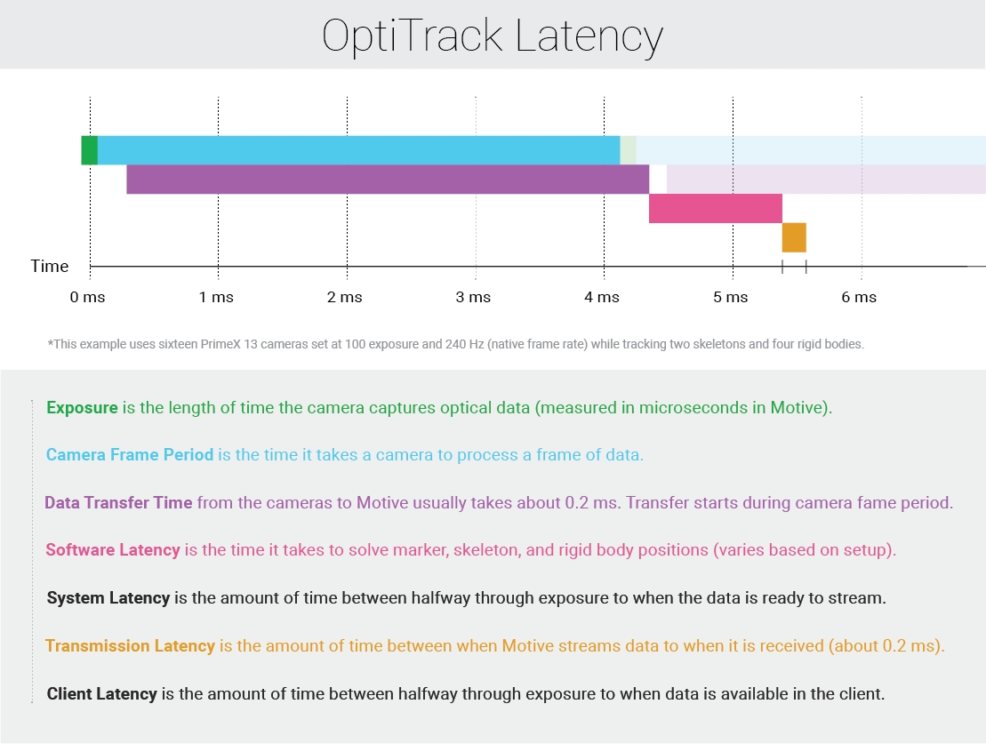
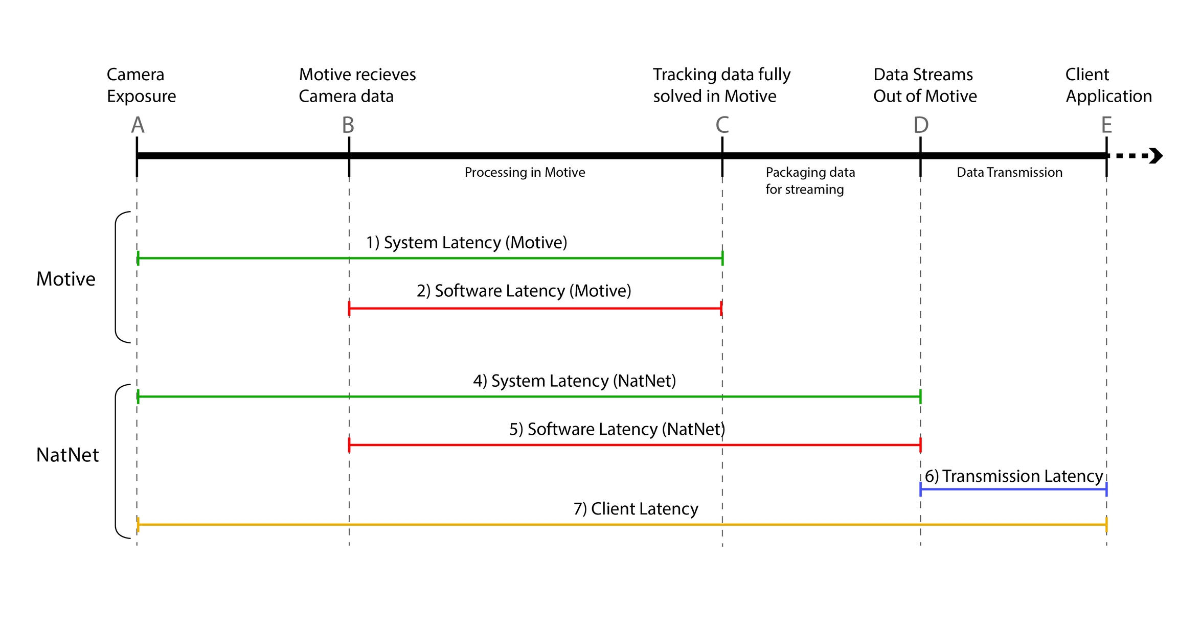
This method calculates and returns the time difference between a specific event in the processing pipeline and when the NatNet client application receives the tracking data. For example, if sFrameOfMocapData::CameraMideExposureTimestamp is inputted, it will return the latency from the camera exposure to when the tracking data is received. For more information on how it is used, read through the Latency Measurements page.
Input Parameters:
(uint64_t) A timestamp value from a sFrameOfMocapData struct.
Returns:
(double) The time, in seconds, past since the provided timestamp.
Once the NatNetSDK library has been imported into a client application, the following helper functions can be used.
These functions are available ONLY for C++ applications.
Description
This function gets the version (#.#.#.#) of the NatNet SDK and saves it into an array.
Input Parameters:
Unsigned char array with a array length of 4.
Returns:
Void
Description
This function assignes a callback handler function for receiving and reporting error/debug messages.
Input Parameters:
pfnLogCallback: NatNetLogCallback function. NatNetLogCallback is a type of a pointer to a callback function that is used to handle the log messages sent from the server application. Format of the linked function must agree with the following type definition:
typedef void (NATNET_CALLCONV* NatNetLogCallback)(Verbosity level, const char* message);
Returns:
Void
Description
Takes an ID of a data set (a marker, a Rigid Body, a Skeleton, or a force plate), and decodes its model ID and member ID into the provided integer variables. For example, ID of a Skeleton bone segment will be decoded into its model ID (Skeleton) and Rigid Body ID (bone). See NatNet: Data Types.
Input Parameters:
An ID value for a respective data set (sRigidBodyData, sSkeletonData, sMarker, or sFrocePLateData) from a sFrameOfMocapData packet.
Pointer to declared integer value for saving the entity ID and the member ID (e.g. Skeleton ID and its bone Rigid Body ID).
Returns:
Void
Description
Helper function to decode OptiTrack timecode data into individual components.
Input Parameters:
Timecode integer from a packet of sFrameOfMocapData. (timecode)
TimecodeSubframe integer from a packet of sFrameOfMocapData. (timecodeSubframe)
Pointers to declared integer variables for saving the hours (pOutHour), minutes (pOutMinute), seconds (pOutSecond), frames (pOutFrame), and subframes (pOutSubframe) values.
Returns:
ErrorCode, On success, it returns 0 or ErrorCode_OK.
Description
Helper function to parse OptiTrack timecode into a user friendly string in the form hh:mm:ss:ff:yy
Input Parameters:
timecode: Timecode integer from a packet of sFrameOfMocapData. (timecode)
timecodeSubframe: TimecodeSubframe integer from a packet of sFrameOfMocapData. (timecodeSubframe)
outBuffer: Declared char for saving the output.
outBufferSize: size of the character array buffer (outBuffer).
Returns:
ErrorCode, On success, it returns 0 or ErrorCode_OK.
Description
This helper function performs a deep copy of frame data from pSrc into pDst. Some members of pDst will be dynamically allocated; use NatNet_FreeFrame( pDst ) to clean them up.
Input Parameters:
Pointer to two sFrameOfMocapData variables to copy from (pSrc) and copy to (pDst).
Returns:
ErrorCode, On success, it returns 0 or ErrorCode_OK.
Description
Frees the dynamically allocated members of a frame copy created using NatNet_CopyFrame function. Note that the object pointed to by pFrame itself is NOT de-allocated, but only its nested members which were dynamically allocated are freed.
Input Parameters:
sFrameOfMocapData that has been copied using the NatNet_CopyFrame function.
Returns:
ErrorCode, On success, it returns 0 or ErrorCode_OK.
Do not call this on any pFrame data that was not the destination of a call to NatNet_CopyFrame.
Description
Deallocates data descriptions pDesc and all of its members; after this call, this object is no longer valid.
Input Parameters:
Data descriptions (sDataDescriptions).
Returns:
ErrorCode, On success, it returns 0 or ErrorCode_OK.
Description
Sends broadcast messages to discover active NatNet servers and blocks for a specified time to gather responses.
Input Parameters:
outServers: An array of length equal to the input value of pInOutNumServers. This array will receive the details of all servers discovered by the broadcast.
pInOutNumServers: A pointer to an integer containing the length of the array. After this function returns, the integer is modified to contain the total number of servers that responded to the broadcast inquiry. If the modified number is larger than the original number passed to the function, there was insufficient space for those additional servers.
timeoutMillisec: Amount of time, in milliseconds, to wait for server responses to the broadcast before returning.
Returns:
ErrorCode, On success, it returns 0 or ErrorCode_OK.
Description
Begin sending periodic broadcast messages to discover active NatNet servers in the background.
Input Parameters:
pOutDiscovery: Out pointer that will receive a handle representing the asynchronous discovery process. The handle returned should be passed to NatNet_FreeAsyncServerDiscovery method later for clean up.
pfnCallback: A NatNetServerDiscoveryCallback function pointer that will be invoked once for every new server that's discovered by the asynchronous search. The callback will also be passed onto the provided pUserContext argument.
pUserContext: User-specified context data to be passed to the provided pfnCallback when invoked.
Returns:
ErrorCode, On success, it returns 0 or ErrorCode_OK.
Description
Begin sending periodic broadcast messages to continuously search and discover active NatNet servers in the background.
Input Parameters:
pOutDiscovery: Out pointer that will receive a handle representing the asynchronous discovery process. The handle returned should be passed to NatNet_FreeAsyncServerDiscovery method later for clean up.
pfnCallback: A NatNetServerDiscoveryCallback function pointer that will be invoked once for every new server that's discovered by the asynchronous search. The callback will also be passed onto the provided pUserContext argument.
pUserContext: User-specified context data to be passed to the provided pfnCallback when invoked.
Returns:
ErrorCode, On success, it returns 0 or ErrorCode_OK.
This page is created to guide help users migrating their NatNet projects onto NatNet 3.0 libraries.
NatNet 3.0 no longer allows static linking of the libraries. If a NatNet project was utilizing NatNetLibStatic.lib to accomplish static linking, you will need to make changes to the project configurations, so that it links dynamically instead.
This is only an example. Required configuration changes may be different depending on how the projects were setup.
Visual Studio Example
Project Settings → Configuration Properties → C/C++ → Preprocessor Definitions: Add "NATNATLIB_IMPORTS"
Project Settings → Configuration Properties → Linker → Input → Additional Dependencies: Change "NatNetLibStatic.lib" to "NatNetLib.lib"
Project Settings → Configuration Properties → Linker → General: Make sure the additional library directories includes the directory where the library files are locate.
In NatNet 3.0, the structure of Rigid Body descriptions and Rigid Body frame data has been slightly modified. The sRigidBodyData:Markers member has been removed, and instead, the Rigid Body description (sRigidBodyDescription) now includes the expected Rigid Body marker positions in respect to the corresponding RB orientation axis.
Per-frame positions of Rigid Body markers have to be derived using the Rigid Body tracking data and the expected Rigid Body markers positions included in the description packet.
SDK/API Support Disclaimer
We provide developer tools to enable OptiTrack customers across a broad set of applications to utilize their systems in the ways that best suit them. Our Motive API through the NatNet SDK and Camera SDK is designed to enable experienced software developers to integrate data transfer and/or system operation with their preferred systems and pipelines. Sample projects are provided alongside each tool, and we strongly recommend the users to reference or use the samples as reliable starting points. The following list specifies the range of support that will be provided for the SDK tools:
Using the SDK tools requires background knowledge on software development; therefore, we do not provide support for basic project setup, compiling, and linking when using the SDK/API to create your own applications.
Although we ensure the SDK tools and their libraries work as intended, we do not provide support for custom developed applications that have been programmed or modified by users using the SDK tools.
Ticketed support will be provided for licensed Motive users using the Motive API and/or the NatNet SDK tools from the included libraries and sample source codes only.
The Camera SDK is a free product, and therefore we do not provide free ticketed support for it.
For other questions, please check out the NaturalPoint forums. Very often, similar development issues get reported and solved there.
This guide provides detailed instructions on commonly used functions of the Motive API for developing custom applications. For a full list of the functions, refer to the Motive API: Function Reference page. Also, for a sample use case of the API functions, please check out the provided marker project. In this guide, the following topics will be covered:
Library files and header files
Initialization and shutdown
Capture setup (Calibration)
Configuring camera settings
Updating captured frames
3D marker tracking
Rigid body tracking
Data streaming
When developing a Motive API project, make sure its linker knows where to find the required library files. This can be done either by specifying its location within the project or by copying these files onto the project folder.
MotiveAPI.h
Motive API libraries (.lib and .dll) are located in the lib folder within the Motive install directory; which is located at C:\Program Files\OptiTrack\Motive\lib by default. In this folder, library files for both 64-bit (MotiveAPI.dll and MotiveAPI.lib) platforms can be found. When using the API library, all of the required DLL files must be located in the executable directory. Copy and paste the MotiveAPI.dll file onto the folder alongside the executable file.
Third-party Libraries
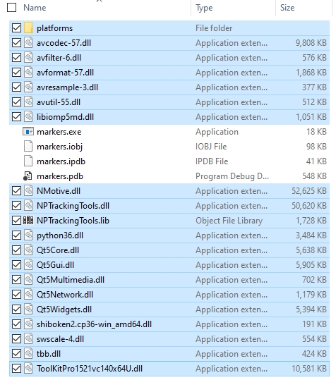
Additional third-party libraries are required for Motive API, and most of the DLL files for these libraries can be found in the Motive install directory C:\Program Files\OptiTrack\Motive\. You can simply copy and paste all of the DLL files from the Motive installation directory into the directory of the Motive API project to use them. Highlighted items in the below image are the required DLL files.
Lastly, copy the C:\Program Files\OptiTrack\Motive\plugins\platforms folder and its contents into the EXE as well since the libraries contained in this folder will also be used.
For function declarations, there are two required header files: MotiveAPI.h and RigidBodySettings.h, and these files are located in the C:\Program Files\OptiTrack\Motive\inc\ folder. Always include the directive syntax for adding the MotiveAPI.h header file for all programs that are developed against the Motive API. The syntax for including RigidBodySetting.h file is already included in the MotiveAPI.h file, so there is no need to include this separately.
The MotiveAPI.h file contains the declaration for most of the functions and classes in the API.
The RigidBodySettings.h file contains declaration for the cRigidBodySettings class, which is used for configuring Rigid Body asset properties.
Note: You could define these directories by using the MOTIVEAPI_INC, MOTIVEAPI_LIB environment variables. Check the project properties (Visual Studio) of the provided marker project for a sample project configuration.
Motive API, by default, loads the default calibration (CAL) and Application profile (MOTIVE) files from the program data directory unless separately specified. These are the files that Motive also loads at the application startup, and they are located in the following folder:
Default System Calibration: C:\ProgramData\OptiTrack\Motive\System Calibration.cal
Default Application Profile: C:\ProgramData\OptiTrack\MotiveProfile.motive
If there are specific files that need to be loaded into the project, you can export and import two files from Motive: motive application profile (MOTIVE) and camera calibration (CAL). The application profile is imported in order to obtain software settings and trackable asset definitions. Only after the camera calibration is imported, reliable 3D tracking data can be obtained. Application profiles can be loaded using the TT_LoadProfile function, and the calibration files can be loaded using the TT_LoadCalibration function.
When using the API, connected devices and the Motive API library need to be properly initialized at the beginning of a program and closed down at the end. The following section covers Motive API functions for initializing and closing down devices.
To initialize all of the connected cameras, call the TT_Initialize function. This function initializes the API library and gets the cameras ready for capturing data, so always call this function at the beginning of a program. If you attempt to use the API functions without the initialization, you will get an error.
Motive Profile Load
Please note that TT_Initialization loads the default Motive profiles (MOTIVE) from the ProgramData directory during the initialization process. To load Motive profile, or settings, from a specified directory, use TT_LoadProfile.
The TT_Update function is primarily used for updating captured frames, which will be covered later, but there is another use. The TT_Update can also be called to update a list of connected devices, and you can call this function after the initialization to make sure all of the newly connected devices are properly initialized in the beginning.
When exiting out of a program, make sure to call the TT_Shutdown function to completely release and close down all of the connected devices. Cameras may fail to shut down completely when this function is not called.
The Motive application profile (MOTIVE) stores all the trackable assets involved in a capture and software configurations including application settings and data streaming settings. When using the API, it is strongly recommended to first configure all of the settings and define trackable assets in Motive, export a profile MOTIVE file, and then load the file by calling the TT_LoadProfile function. This way, you can adjust the settings for your need in advance and apply them to your program without worrying about configuring individual settings.
Cameras must be calibrated in order to track in 3D space. However, since camera calibration is a complex process, and because of this, it's easier to have the camera system calibrated from Motive, export the camera calibration file (CAL), and the exported file can be loaded into custom applications that are developed against the API. Once the calibration data is loaded, the 3D tracking functions can be used. For detailed instructions on camera calibration in Motive, please read through the Calibration page.
Loading Calibration
Open Motive.
[Motive] Calibrate: Calibrate camera system using the Calibration panel. Read through the Calibration page for details.
[Motive] Export: After the system has been calibrated, export the calibration file (CAL) from Motive.
Close out of Motive.
[API] Load: Import calibration onto your custom application by calling the TT_LoadCalibration function to import CAL files.
When successfully loaded, you will be able to obtain 3D tracking data using the API functions.
Note:
Calibration Files: When using the exported calibration files, make sure to use only valid calibration. Exported calibration file can be used again as long as the system setup remains unchanged. Note that the file will no longer be valid if any of the system setups have been altered after the calibration. Also, calibration quality may degrade over time due to environmental factors. For these reasons, we recommend re-calibrating the system routinely to guarantee the best tracking quality.
Tracking Bars: If you are using a tracking bar, camera calibration is not required for tracking 3D points.
Connected cameras are accessible by index numbers. The camera indexes are assigned in the order the cameras are initialized. Most of the API functions for controlling cameras require an index value. When processing all of the cameras, use the TT_CameraCount function to obtain the total camera count and process each camera within a loop. For pointing to a specific camera, you can use the TT_CameraID or TT_CameraName functions to check and use the camera with given its index value. This section covers Motive API functions for checking and configuring camera frame rate, camera video type, camera exposure, pixel brightness threshold, and IR illumination intensity.
The following functions return integer values for the configured settings of a camera specified by its index number. Camera video type is returned as an integer value that represents a image processing mode, as listed in the NPVIDEOTYPE.
These camera settings are equivalent to the settings that are listed in the Devices pane of Motive. For more information on each of the camera settings, refer to the Devices pane page.
Now that we have covered functions for obtaining configured settings, now let's modify some of them. There are two main functions for adjusting the camera settings: TT_SetCameraSettings and TT_SetCameraFramerate. The TT_SetCameraSettings function configures video type, exposure, threshold, and intensity settings of a camera which is specified by its index number. The TT_SetCameraFrameRate is used for configuring frame rate of a camera. Supported frame rate range may vary for different camera models. Check the device specifications and apply the frame rates only within the supported range.
If you wish to keep part of the current camera settings, you can use the above functions to obtain the configured settings (e.g. TT_CameraVideoType, TT_CameraFrameRate, TT_CameraExposure, etc.) and use them as input arguments for the TT_SetCameraSettings function. The following example demonstrates modifying frame rate and IR illumination intensity for all of the cameras, while keeping the other settings constant.
Camera Settings
Valid frame rate values: Varies depending on camera models, refer to the respective hardware specifications.
Valid exposure values: Depends on camera model and frame rate settings.
Valid threshold values: 0 - 255
Valid intensity values: 0 - 15
Video Types
Video Type: see the Data Recording page for more information on image processing modes.
Segment Mode: 0
Grayscale Mode: 1
Object Mode: 2
Precision Mode: 4
MJPEG Mode: 6
There are other camera settings, such as imager gain, that can be configured using the Motive API. Please refer to the Motive API: Function Reference page for descriptions on other functions.
In order to process multiple consecutive frames, you must update the camera frames using the following API functions: TT_Update or TT_UpdateSingleFrame. Call one of the two functions repeatedly within a loop to process all of the incoming frames. In the 'marker sample', TT_Update function is called within a while loop as the frameCounter variable is incremented, as shown in the example below.
There are two functions for updating the camera frames: TT_Update and TT_UpdateSingleFrame. At the most fundamental level, these two functions both update the incoming camera frames. However, they may act differently in certain situations. When a client application stalls momentarily, it could get behind on updating the frames and the unprocessed frames may be accumulated. In this situation, each of these two functions will behave differently.
The TT_Update() function will disregard accumulated frames and service only the most recent frame data, but it also means that the client application will not be processing the previously missed frames.
The TT_UpdateSingleFrame() function ensures that only one frame is processed each time the function is called. However, when there are significant stalls in the program, using this function may result in accumulated processing latency.
In general, a user should always use TT_Update(). Only in the case where a user wants to ensure their client application has access to every frame of tracking data and they are having problems calling TT_Update() in a timely fashion, should they consider using TT_UpdateSingleFrame(). If it is important for your program to obtain and process every single frame, use the TT_UpdateSingleFrame() function for updating the data.
After loading valid camera calibration, you can use the API functions to track retroreflective markers and get their 3D coordinates. The following section demonstrates using the API functions for obtaining the 3D coordinates. Since marker data is obtained for each frame, always call the TT_Update, or the TT_UpdateSingleFrame, function each time newly captured frames are received.
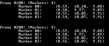
Marker Index
In a given frame, each reconstructed marker is assigned a marker index number. These marker indexes are used for pointing to a particular reconstruction within a frame. You can also use the TT_FrameMarkerCount function to obtain the total marker count and use this value within a loop to process all of the reconstructed markers. Marker index values may vary between different frames, but unique identifiers will always remain the same. Use the TT_FrameMarkerLabel function to obtain the individual marker labels if you wish to access same reconstructions for multiple frames.
Marker Position
For obtaining 3D position of a reconstructed marker, you can use TT_FrameMarkerX, TT_FrameMarkerY, and TT_FrameMarkerZ functions. These functions return 3D coordinates (X/Y/Z) of a marker in respect to the global coordinate system, which was defined during the calibration process. You can further analyze 3D movements directly from the reconstructed 3D marker positions, or you can create a Rigid Body asset from a set of tracked reconstructions for 6 Degrees of Freedom tracking data. Rigid body tracking via the API will be explained in the later section.
For tracking 6 degrees of freedom (DoF) movement of a Rigid Body, a corresponding Rigid Body (RB) asset must be defined. A RB asset is created from a set of reflective markers attached to a rigid object which is assumed to be undeformable. There are two main approaches for obtaining RB assets when using Motive API; you can either import existing Rigid Body data or you can define new Rigid Bodies using the TT_CreateRigidBody function. Once RB assets are defined in the project, Rigid Body tracking functions can be used to obtain the 6 DoF tracking data. This section covers sample instructions for tracking Rigid Bodies using the Motive API.
We strongly recommend reading through the Rigid Body Tracking page for more information on how Rigid Body assets are defined in Motive.
Let's go through importing RB assets into a client application using the API. In Motive, Rigid Body assets can be created from three or more reconstructed markers, and all of the created assets can be exported out into either application profile (MOTIVE) or a Motive Rigid Body file (TRA). Each Rigid Body asset saves marker arrangements when it was first created. As long as the marker locations remain the same, you can use saved asset definitions for tracking respective objects.
Exporting all RB assets from Motive:
Exporting application profile: File → Save Profile
Exporting Rigid Body file (TRA): File → Export Rigid Bodies (TRA)
Exporting individual RB asset:
Exporting Rigid Body file (TRA): Under the Assets pane, right-click on a RB asset and click Export Rigid Body
When using the API, you can load exported assets by calling the TT_LoadProfile function for application profiles and the TT_LoadRigidBodies or TT_AddRigidBodes function for TRA files. When importing TRA files, the TT_LoadRigidBodies function will entirely replace the existing Rigid Bodies with the list of assets from the loaded TRA file. On the other hand, TT_AddRigidBodes will add the loaded assets onto the existing list while keeping the existing assets. Once Rigid Body assets are imported into the application, the API functions can be used to configure and access the Rigid Body assets.
Rigid body assets can also be defined directly using the API. The TT_CreateRigidBody function defines a new Rigid Body from given 3D coordinates. This function takes in an array float values which represent x/y/z coordinates or multiple markers in respect to Rigid Body pivot point. The float array for multiple markers should be listed as following: {x1, y1, z1, x2, y2, z2, …, xN, yN, zN}. You can manually enter the coordinate values or use the TT_FrameMarkerX, TT_FrameMarkerY, and TT_FrameMarkerZ functions to input 3D coordinates of tracked markers.
When using the TT_FrameMarkerX/Y/Z functions, you need to keep in mind that these locations are taken in respect to the RB pivot point. To set the pivot point at the center of created Rigid Body, you will need to first compute pivot point location, and subtract its coordinates from the 3D coordinates of the markers obtained by the TT_FrameMarkerX/Y/Z functions. This process is shown in the following example.
Example: Creating RB Assets
6 DoF Rigid Body tracking data can be obtained using the TT_RigidBodyLocation function. Using this function, you can save 3D position and orientation of a Rigid Body into declared variables. The saved position values indicate location of the Rigid Body pivot point, and they are represented in respect to the global coordinate axis. The Orientation is saved in both Euler and Quaternion orientation representations.
Example: RB Tracking Data
In Motive, Rigid Body assets have Rigid Body properties assigned to each of them. Depending on how these properties are configured, display and tracking behavior of corresponding Rigid Bodies may vary. When using the API, Rigid Body properties are configured and applied using the cRigidBodySettings class which is declared within the RigidBodySetting.h header file.
Within your program, create an instance of cRigidBodySettings class and call the API functions to obtain and adjust Rigid Body properties. Once desired changes are made, use the TT_SetRigidBodySettings function to assign the properties back onto a Rigid Body asset.
For detailed information on individual Rigid Body settings, read through the Properties: Rigid Body page.
Once the API has been successfully initialized, data streaming can be enabled, or disabled, by calling either the TT_StreamNP, TT_StreamTrackd, or TT_StreamVRPN function. The TT_StreamNP function enables/disables data streaming via the NatNet. The NatNet SDK is a client/server networking SDK designed for sending and receiving NaturalPoint data across networks, and tracking data from the API can be streamed to client applications from various platforms via the NatNet protocol. Once the data streaming is enabled, connect the NatNet client application to the server IP address to start receiving the data.
The TT_StreamNP function is equivalent to Broadcast Frame Data from the Data Streaming pane in Motive.
The Motive API does not currently support configuring data streaming settings directly from the API. To configure the streaming server IP address and the data streaming settings, you will need to use Motive and save an application profile MOTIVE file that contains the desired configuration. Then, the exported profile can be loaded when using the API. Through this way, you will be able to set the interface IP address and decide which data to be streamed over the network.
For more information on data streaming settings, read through the Data Streaming page.
An overview of the NatNet SDK.
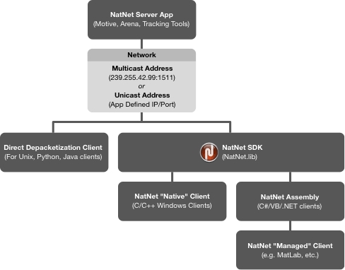
The NatNet SDK is a networking software development kit (SDK) for receiving OptiTrack data across networks. It allows streaming of live or recorded motion capture data from a tracking server (e.g. Motive) into various client applications. Using the SDK, you can develop custom client applications that receive data packets containing real-time tracking information and send remote commands to the connected server. NatNet uses the UDP protocol in conjunction with either Point-To-Point Unicast or IP Multicasting for sending and receiving data. The following diagram outlines the major components of a typical NatNet network setup and how they establish communication between NatNet server and client application.
For previous versions of NatNet, please refer to the provided PDF user guide that ships with the SDK.
Please read through the changelog for key changes in this version.
NatNet is backwards compatible with any version of Motive, however, older versions may be missing features that are present in newer versions.
The NatNet SDK consists of the following:
NatNet Library: Native C++ networking library contents, including the static library file (.lib), the dynamic library file (.dll), and the corresponding header files.
NatNet Assembly: Managed .NET assembly (NatNetML.dll) for use in .NET compatible clients.
NatNet Samples: Sample projects and compiled executables designed to be quickly integrated into your code.
A NatNet server (e.g. Motive) has 2 threads and 2 sockets: one for sending tracking data to a client and one for sending/receiving commands.
NatNet servers and clients can exist either on a same machine or on separate machines.
Multiple NatNet clients can connect to a single NatNet server.
When a NatNet server is configured to use IP Multicast, the data is broadcasted only once, to the Multicast group.
Default multicast IP address: 239.255.42.99 and Port: 1511.
IP address for unicast is defined by a server application.
The NatNet SDK is shipped in a compressed ZIP file format. Within the unzipped NatNet SDK directory, the following contents are included:
Sample Projects: NatNet SDK\Samples
The Sample folder, contains Visual Studio 2013 projects that use the NatNetSDK libraries for various applications. These samples are the quickest path towards getting NatNet data into your application. We strongly recommend taking a close look into these samples and adapt applicable codes into your application. More information on these samples are covered in the NatNet Samples page.
Library Header Files: NatNet SDK\include
The include folder contains headers files for using the NatNet SDK library.
\include\NatNetTypes.h
NatNetTypes.h header file contains the type declaration for all of the data formats that are communicated via the NatNet protocol.
\include\NatNetClient.h
\include\NatNetRequests.h
\include\NatNetRepeater.h
NatNetRepeater.h header file controls how big the packet sizes can be.
\include\NatNetCAPI.h
NatNetCAPI.h header file contains declaration for the NatNet API helper functions. These functions are featured for use with native client applications only.
Library DLL Files: NatNet SDK\lib
NatNet library files are contained in the lib folder. When running applications that are developed against the NatNet SDK library, corresponding DLL files must be placed alongside the executables.
\lib\x64
This folder contains NatNet SDK library files for 64-bit architecture.
\lib\x64\NatNetLib.dll
Native NatNet library for 64-bit platform architecture. These libraries are used for working with NatNet native clients.
\lib\x64\NatNetML.dll
Managed NatNet assembly files for 64-bit platform architecture. These libraries are used for working with NatNet managed clients, including applications that use .NET assemblies.
Note that this assembly is derived from the native library, and to use the NatNetML.dll, NatNetLib.dll must be linked as well.
\lib\x64\NatNetML.xml
Includes XML documentations for use with the NatNetML.dll assembly. Place this alongside the DLL file to view the assembly reference.
\lib\x86
No longer supported in 4.0
\lib\x86\NatNetLib.dll
No longer supported in 4.0.
\lib\x86\NatNetML.dll
No longer supported in 4.0.
\lib\x86\NatNetML.xml
No longer supported in 4.0.
NatNet class and function references for the NatNetClient object.
List of tracking data types available in the NatNet SDK streaming protocol.
NatNet commands for remote triggering the server application
NatNet commands for subscribing to specific data types only.
Tip: Code samples are the quickest path towards getting familiar with the NatNet SDK. Please check out the NatNet samples page.
List of NatNet sample projects and the instructions.
Timecode representation in OptiTrack systems and NatNet SDK tools.
A general guideline to using the NatNet SDK for developing a native client application.
A general guideline to using the NatNet SDK for developing a managed client application.
In streamed NatNet data packets, orientation data is represented in the quaternion format (qx, qy, qz, qw). In contrast to Euler angles, Quaternion orientation convention is order independent, however, it indicates the handedness. When converting quaternion orientation into Euler angles, it is important to consider and decide which coordinate convention that you want to convert into. Some of the provided NatNet samples demonstrate quaternion to Euler conversion routines. Please refer to the included WinFormSample, SampleClient3D, or Matlab samples for specific implementation details and usage examples.
To convert from provided quaternion orientation representation, the following aspects of desired Euler angle convention must be accounted:
Rotation Order
Handedness: Left handed or Right handed
Axes: Static (Global) or relative (local) axes.
For example, Motive uses the following convention to display the Euler orientation of an object:
Rotation Order: X (Pitch), Y (Yaw), Z (Roll)
Handedness: Right-handed (RHS)
Axes: Relative Axes (aka 'local')
Important Note: Use of the direct depacketization is not recommended. The syntax of the bit-stream packets is subject to change, requiring an application to update its parsing routines to be compatible with the new format. The direct depacketization approach should be used only where the use of the NatNet library is not applicable.
In situations where the use of the NatNet library is not applicable (e.g. developing on unsupported platforms such as Unix), you can also depacketize the streamed data directly from the raw bit-stream without using the NatNet library. In order to provide the most current bitstream syntax, the NatNet SDK includes a testable working depacketization sample (PacketClient, PythonClient) that decodes NatNet Packets directly without using the NatNet client class.
For the most up-to-date syntax, please refer to either the PacketClient sample or the PythonClient sample to use them as a template for depacketizing NatNet data packets.
Adapt the PacketClient sample (PacketClient.cpp) or the PythonClient sample (PythonSample.py) to your application's code.
Regularly update your code with each revision to the NatNet bitstream syntax.
When working in Edit mode, pause playback in Motive to view the streamed data. Press the h key to display the NatNet help screen for additional commands.
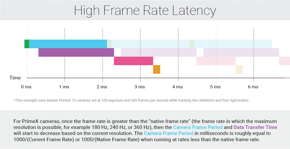
The 4.0 update includes bit-stream syntax changes to allow up to 32 force plates to be streamed at once. This requires corresponding updates for each program that uses the direct depacketization approach for parsing streamed data. A system under 32 force plates should still avoid using direct depacketization. See the Important Note above in the Direct Depacketization section for more information.
Starting from Motive 3.0, you can send NatNet remote commands to Motive and select the version of bitstream syntax to be outputted from Motive. This is accomplished by sending a command through the command port. For details on doing this, please refer to the SetNatNetVersion function demonstrated in the PacketClient.
Bit-Stream NatNet Versions
NatNet 4.1 (Motive 3.1)
NatNet 4.0 (Motive 3.0)
NatNet 3.1 (Motive 2.1)
NatNet 3.0 (Motive 2.0)
NatNet 2.10 (Motive 1.10)
NatNet 2.9 (Motive 1.9)
here are three OptiTrack developer tools for developing custom applications: the Camera SDK, the NatNet SDK, and the Motive API. All of the tools support a C/C++ interface to OptiTrack cameras and provides control over OptiTrack motion capture systems.
Visit our website to compare OptiTrack developer tools and their functions.
SDK/API Support Disclaimer
We provide developer tools to enable OptiTrack customers across a broad set of applications to utilize their systems in the ways that best suit them. Our Motive API through the NatNet SDK and Camera SDK is designed to enable experienced software developers to integrate data transfer and/or system operation with their preferred systems and pipelines. Sample projects are provided alongside each tool, and we strongly recommend the users to reference or use the samples as reliable starting points. The following list specifies the range of support that will be provided for the SDK tools:
Using the SDK tools requires background knowledge on software development; therefore, we do not provide support for basic project setup, compiling, and linking when using the SDK/API to create your own applications.
Although we ensure the SDK tools and their libraries work as intended, we do not provide support for custom developed applications that have been programmed or modified by users using the SDK tools.
Ticketed support will be provided for licensed Motive users using the Motive API and/or the NatNet SDK tools from the included libraries and sample source codes only.
The Camera SDK is a free product, and therefore we do not provide free ticketed support for it.
For other questions, please check out the NaturalPoint forums. Very often, similar development issues get reported and solved there.
Go to the Camera SDK page: Camera SDK
The Camera SDK provides hardware (cameras and hubs) controls and access to the most fundamental frame data, such as grayscale images and 2D object information, from each camera. Using the Camera SDK, you can develop your own image processing applications that utilize the capabilities of the OptiTrack cameras. The Camera SDK is a free tool that can be downloaded from our website.
Note: 3D tracking features are not directly supported with Camera SDK, but they are featured via the Motive API. For more information on the Camera SDK, visit our website.
Go to the Motive API page: Motive API
The Motive API allows control of, and access to, the backend software platform of Motive. Not only does it allow access to 2D camera images and the object data, but it also gives control over the 3D data processing pipeline, including solvers for the assets. Using the Motive API, you can employ the features of Motive into your custom application.
Note: When you install Motive, all of the required components for utilizing the API will be installed within the Motive install directory.
Go to the NatNet SDK page: NatNet SDK 4.0
The NatNet SDK is a client/server networking SDK designed for sending and receiving NaturalPoint data across networks. The NatNet SDK makes the motion capture data available to other applications in real-time. It utilizes UDP along with either Unicast or Multicast communication for integrating and streaming 3D reconstructed data, Rigid Body data, and Skeleton data from OptiTrack systems. Using the NatNet SDK, you can develop custom client/server applications that utilize motion capture data. The NatNet SDK is a free tool that can be downloaded from our website.
Visit our website or Data Streaming page for more information on NatNet SDK.
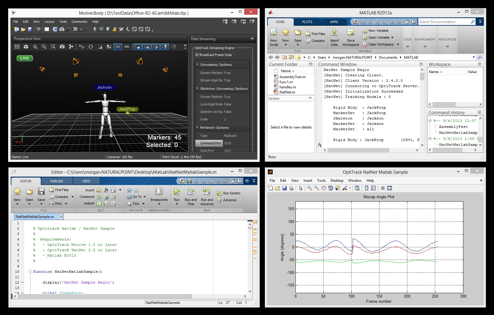
To ease your use of NatNet data in MATLAB applications, we provide a wrapper class (natnet.p) for using real-time streamed NatNet data. Using this class, you can easily connect/disconnect to the server, receive the tracking data, and parse each component.
The Matlab-NatNet wrapper class is a wrapper for the NatNet assembly and provides a simplified interface for managing the native members in MATLAB. The class definition and supporting code should be placed within the MATLAB PATH. The implementation automatically disposes running connections when ending a streaming session, along with basic object management. In order to use the Matlab wrapper class, the NatNetML assembly must be loaded into the MATLAB session. This is handled automatically and the first time the class is used the user is prompted to find the NatNetML.dll file in the Windows file browser. A reference to this location is used in future MATLAB sessions.
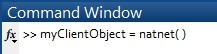
To create an instance of the natnet wrapper class, simply call the class with no input arguments and store it in a variable.
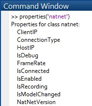
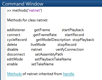
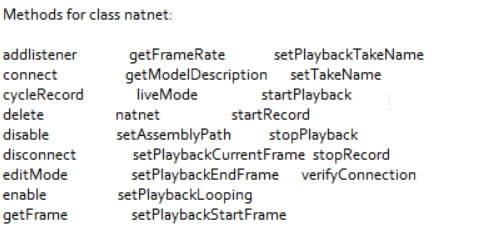
Class Properties: The available properties to the class can be seen with the following command, properties('natnet').
Class Methods: And Available methods
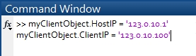
Creating an instance of the class does not automatically connect the object to a host application. After enabling the broadcast frame data under the Data Streaming pane in Motive or in any other server, configure the connection type and IP addresses for the client and host to reflect your network setup.
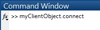
Then enter the following line to call the connect method for connecting to the natnet object to the host.
When creating a natnet class instance, the default host and client IP address is set to '127.0.0.1', which is the local loopback address of the computer. The natnet object will fail to connect if the network address of the host or client is incorrect.
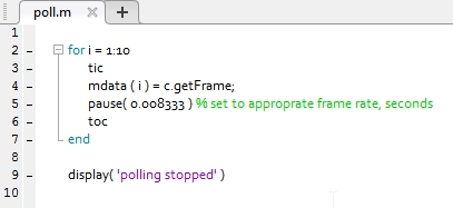
The natnet wrapper class interface has a method to poll mocap data called getFrame. getFrame method returns the data structure of the streamed data packet. Polling is supported but not recommended due to accessing errors. The function, poll.m, provides a simple example showing out to poll the frames of mocap data. After connecting the natnet object to the host server, run the polling script to acquire the data packets in the main workspace.
The natnet class implements a simple interface to use event callbacks. The natnet method, addlistener, requires two input arguments. The first input is which listener slot to use, and the second is the name of the m-function file to be attached to the listener. Once the function is attached using addlistener method, it will be called each time a frame is received. When the callback function is first created, the listener is turned off by default. This is to ensure the user had control of the execution of the even callback function.
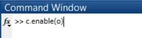
Enabling Listener: Start receiving streamed data by enabling the callback function by calling the enable method. The input of the enable method indicates the index value of the listener to enable. Multiple functions can be attached to the listener, and you can enable a specific listener by inputting its index value. Entering 0 will enable all listeners.
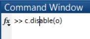
Disabling Listener: There are three types of callback functions that ships with the natnet class. IF they are added to the natnet listener list and enabled, they will execute each time the host sends a frame of data. The setup.m file, contains an example of how to operate the class. To stop streaming, use the disable method and be sure to enter a value of 0 to disable all listeners.
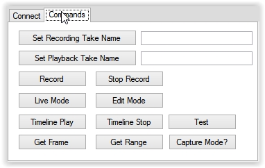
The natnet class also has functionality to control the Motive application. To enable recording use the startRcord and stopRecord methods, and for playback, use the startPlayback and stopPlayback methods. There are a number of additional commands as shown below.
To display the actions of the class, set the IsReporting property to true. This displays operations of the class to the Command Window.
An overview of the general data structure used in the NatNet software development kit (SDK) and how the library is used to parse received tracking information.
For specific details on each of the data types, please refer to the header file.
When receiving streamed data using the NatNet SDK library, its data descriptions should be received before receiving the tracking data.
NatNet data is packaged mainly into two different formats: data descriptions and frame-specific tracking data. Utilizing this format, the client application can discover which data are streamed out from the server application prior to accessing the actual tracking data.
For every asset (e.g., reconstructed markers, Rigid Bodies, Skeletons, force plates) included within streamed capture sessions, the description and tracking data are stored separately. This format allows frame-independent parameters (e.g., name, size, and number) to be stored within instances of the description structs, and frame-dependent values (e.g. position and orientation) to be stored within instances of the frame data structs. When needed, two different packets of an asset can be correlated by referencing its unique identifier values.
Dataset Descriptions contains descriptions of the motion capture data sets for which a frame of motion capture data will be generated. (e.g. sSkeletonDescription, sRigidBodyDescription)
Frame of Mocap Data contains a single frame of motion capture data for all the datasets described from the Dataset Descriptions. (e.g. sSkeletonData, sRigidBodyData)
When streaming from Motive, received NatNet data will contain only the assets that are enabled in the and the asset types that are set to true under Streaming Settings in the tab in Motive Settings.
To receive data descriptions from a connected server, use the method. Calling this function saves a list of available descriptions in an instance of sDataSetDescriptions.
The sDataSetDescriptions structure stores an array of multiple descriptions for each asset (Marker Sets, RigidBodies, Skeletons, and Force Plates) involved in a capture and necessary information can be parsed from it.
Refer to the header file for more information on each data type and members of each description struct.
The following section lists the main data description structs that are available through the SDK.
Saved struct Type: Native Library: sServerDescription
Saved struct Type: Managed Assembly: ServerDescription
Contains basic network information of the connected server application and the host computer that it is running on. Server descriptions are obtained by calling the GetServerDescription method from the NatNetClient class.
Host connection status
Host information (computer name, IP, server app name)
NatNet version
Host's high resolution clock frequency. Used for calculating the latency
Connection status
Saved struct Type: Native Library: sDataDescriptions
Saved struct Type: Managed Assembly: List<DataDescriptor>
Contains an array of data descriptions for each active asset in a capture, and basic information about corresponding asset is stored in each description packet. Data descriptions are obtained by calling the GetDataDescriptions method from the NatNetClient class. Descriptions of each asset type is explained below.
Saved struct Type: Native Library: sMarkerSetDescription
Saved struct Type: Managed Assembly: MarkerSet
Marker Set description contains a total number of markers in a Marker Set and each of their labels. Note that Rigid Body and Skeleton assets are included in the Marker Set as well. Also, for every mocap session, there is a special MarkerSet named all, which contains a list of all of the labeled markers from the capture.
Name of the Marker Set
Number of markers in the set
Marker names
Saved struct Type: Native Library: sRigidBodyDescription
Saved struct Type: Managed Assembly: RigidBody
Rigid Body description contains corresponding Rigid Body names. Skeleton bones are also considered as Rigid Bodies, and in this case, the description also contains hierarchical relationship for parent/child Rigid Bodies.
Rigid Body name
Rigid Body streaming ID
Rigid Body parent ID (when streaming Skeleton as Rigid Bodies)
Offset displacement from the parent Rigid Body
Array of marker locations that represent the expected marker locations of the Rigid Body asset.
Saved struct Type: Native Library: sSkeletonDescription
Saved struct Type: Managed Assembly: Skeleton
Skeleton description contains corresponding Skeleton asset name, Skeleton ID, and total number of Rigid Bodies (bones) involved in the asset. The Skeleton description also contains an array of Rigid Body descriptions which relates to individual bones of the corresponding Skeleton.
Name of the Skeleton
Skeleton ID: Unique identifier
Number of Rigid Bodies (bones)
Array of bone descriptions
Note: Beginning with NatNet 3.0, Skeleton bone data description packet changed from left-handed convention to right-handed convention to be consistent with the convention used in all other data packets. For older versions of NatNet clients, the server, Motive, will detect the client version and stream out Skeleton data in the matching convention. This change will only affect direct depacketization clients as well as clients that have the NatNet library upgraded to 3.0 from previous versions; for those clients, corresponding changes must be made to work with Motive 2.0.
Saved struct Type: Native Library: sAssetDescription
Saved struct Type: Managed Assembly: Asset
Asset description contains corresponding data for trained markerset assets:
Asset type - Trained Markerset
Asset name
Asset ID: Unique identifier
Number of markers
Number of Rigid Bodies (bones) in the asset
The following asset-specific arrays are also included:
Rigid Body (bone) descriptions
Marker descriptions
Saved struct Type: Native Library: sForcePlateDescription
Saved struct Type: Managed Assembly: ForcePlate
Force plate ID and serial number
Force plate dimensions
Electrical offset
Number of channels
Channel info
More. See NatNetTypes.h file for more information
Saved struct Type: Native Library: sCameraDescription
Saved struct Type: Managed Assembly: Camera
An instance of the sCameraDescription contains information regarding the camera name, its position, and orientation.
Camera Name (can be used with Get/Set property commands)
Camera Position (x, y, z float variables)
Camera Orientation (qx, qy, qz, qw float variables)
For more info, see the NatnetTypes.h file.
Saved struct Type: Native Library: sDeviceDescription
Saved struct Type: Managed Assembly: Device
Device ID. Used only for identification of devices in the stream.
Device Name
Device serial number
Device Type
Channel count
Channel Names
As mentioned in the beginning, frame-specific tracking data are stored separately from the DataDescription instances as this cannot be known ahead of time or out of band but only by per frame basis. These data get saved into instances of sFrameOfMocapData for corresponding frames, and they will contain arrays of frame-specific data structs (e.g.sRigidBodyData, sSkeletonData) for each types of assets included in the capture. Respective frame number, timecode, and streaming latency values are also saved in these packets.
FrameOfMocapData
Refer to the NatNetTypes.h header file or the NatNetML.dll assembly for the most up to date descriptions of the types.
Most of the NatNet SDK data packets contain ID values. This value is assigned uniquely to individual markers as well as each of assets within a capture. These values can be used to figure out which asset a given data packet is associated with. One common use is for correlating data descriptions and frame data packets of an asset.
Decoding Member IDs
For each member object that is included within a parental model, its unique ID value points to both its parental model and the member itself. Thus, the ID value of a member object needs to be decoded in order to parse which objects and the parent models they are referencing to.
For example, a Skeleton asset is a hierarchical collection of bone Rigid Bodies, and each of its bone Rigid Bodies has unique ID that references to the involved Skeleton model and the Rigid Body itself. When analyzing Skeleton bones, its ID value needs to be decoded in order to extract the segment Rigid Body ID, and only then, it can be used to reference its descriptions.
The following guide references SampleClientML.cs client application that is provided with the SDK. This sample demonstrates the use of .NET NatNet assembly for connecting to a NatNet server, receiving a data stream, and parsing and printing out the received data.
SDK/API Support Disclaimer
We provide developer tools to enable OptiTrack customers across a broad set of applications to utilize their systems in the ways that best suit them. Our Motive API through the NatNet SDK and Camera SDK is designed to enable experienced software developers to integrate data transfer and/or system operation with their preferred systems and pipelines. Sample projects are provided alongside each tool, and we strongly recommend the users to reference or use the samples as reliable starting points. The following list specifies the range of support that will be provided for the SDK tools:
Using the SDK tools requires background knowledge on software development; therefore, we do not provide support for basic project setup, compiling, and linking when using the SDK/API to create your own applications.
Although we ensure the SDK tools and their libraries work as intended, we do not provide support for custom developed applications that have been programmed or modified by users using the SDK tools.
Ticketed support will be provided for licensed Motive users using the Motive API and/or the NatNet SDK tools from the included libraries and sample source codes only.
The Camera SDK is a free product, and therefore we do not provide free ticketed support for it.
For other questions, please check out the . Very often, similar development issues get reported and solved there.
When developing a managed client applications, you will need to link both native and managed DLL files(NatNetLib.dll and NatNetML.dll). The managed NatNet assembly is derived from the native library, so without the NatNetLib.dll, NatNetML.dll will not be imported properly. These library files can be found in the NatNetSDK\lib folder for 32-bit platform and in the NatNetSDK\lib\x64 folder for 64-bit platform. Make sure these DLL files are properly linked and placed alongside the executables.
Also, when using the NatNetML assembly, place the NatNetML.xml file alongside imported DLL file. This allows XML documentation to be included as a reference. These library files can be found in the NatNetSDK\lib folder for 32-bit platform and in the NatNetSDK\lib\x64 folder for 64-bit platform. Make sure these DLL files are properly linked and placed alongside the executables.
Tracking server and client network is established through an instance of NatNet client object (NatNetML.NatNetClientML). Also, this NatNetClientML object will be used for receiving tracking data and sending NatNet commands to and from the server application. When instantiating the NatNetClientML object, input an integer value for determining the desired type of UDP connection; whether it connects via multicast (0) or unicast (1).
Server Discovery
You can also use the NatNetServerDiscover class to auto-detect available servers to connect to. This is demonstrated in the WinFromSamplesApp**.**
GetDataDescriptions method in the NatNetClientML class queries a list of DataDescriptors from the connected server and saves it in a declared list of NatNetML.DataDescriptions. In the SampleClientML sample, the following lines are executed to accomplish this:
After obtaining a list of data descriptions, use the saved DataDescriptor objects to access and output data descriptions as needed. In many cases, it is better to re-organize and save the received descriptor objects into separate lists, or into hashtables, of corresponding data types, so that they can be referenced later in the program.
The best way to receive tracking data without losing any of its frames is to create a callback handler function for processing the data. The OnFrameReady event type from the client object can be used to declare a callback event, and the linked function gets called each time a frame is received from the server. Setting up a frame handler function will ensure that every frame gets processed promptly. However, these handler functions should return as quickly as possible to prevent accumulation of frames due to processing latency within the handler.
OnFrameReady2: Alternate function signatured frame ready callback handler for .NET applications/hosts that don't support the OnFrameReady event type defined above (e.g. MATLAB)
Calling the GetLastFrameOfData method returns a FrameOfMocapData of the most recent frame that was streamed out from the connected server application. This approach is should only be used for .NET applications/hosts that do not support the OnFrameReady callback handler function.
This function is supported in NatNetML only. Native implementations should always use the callback handlers.
When exiting the program, call Uninitialize method using the connected client object and disconnect the client application from the server.
This document provides general guidelines to create a device plugin for external glove devices in Motive.
Starting with Motive 3.1, an example project, GloveDeviceExample, is included along with the peripheral API library. This guide will reference that example and provide basic information on how to use the peripheralimport library (LIB) to create glove device plugins and identify required configuration settings.
This guide assumes that you have access to Motive 3.1 or above. Additional descriptions are commented throughout the source and header files also.
Mocap systems often incorporate external measurement systems in order to accomplish more complex analysis. Commonly integrated devices include force plates, data acquisition boards, and EMG sensors.
There are a few different ways to combine data with external systems: recorded data sets can be analyzed in post-capture; data can be streamed real-time into a client application and then combined downstream; or data can be combined live in Motive using the plugin interface. With finger-tracking devices, the workflow is much simpler if the motion capture data of the two systems gets joined together in Motive.
In this article, we will show how to integrate glove devices using the plugin interface provided by the (peripheralimport.lib), which is used to create and manage plugin devices in Motive.
Glove devices update the local quaternion rotation of the finger bones. The hand skeleton in Motive is made up of 15 bone joints, three bones per finger. Each bone will require 4 float values to represent the quaternion rotation. In total, 60 float analog channels will be created for the glove device.
The hand orientation in Motive respects the right-handed coordinate system. For the left hand, the local coordinate is +X pointing towards the fingertips when in T-pose, and for the right hand, +X points towards the wrist/body when in T-pose.
The glove device example is a guide for integrating glove devices into Motive. This project is located in:
[Motive Installation Directory]\PeripheralAPI\example\GloveDeviceExample
Parts of the GloveDeviceExample code can be replaced with calls to the SDK in order to initialize, connect, receive, and map the glove data into Motive. These are annotated with placeholder comments throughout the source files. The glove device example project includes some of the base classes that can be inherited:
GloveDeviceFactoryBase class, which handles instantiation and initialization of glove device in Motive.
GloveDeviceBase class, which extends the cPluginDevice class of the peripheral API, and abstracts out the required configurations for glove devices.
ExampleGloveDevice and ExampleGloveAdapterSingleton are sample implementations of a glove plugin by inheriting the above base classes.
HardwareSimulator class is a dummy device to simulate callbacks for the device connection and device data update.
To create a glove SDK, this example can be used as a template and the callbacks can be replaced with the SDK functions that will connect and report glove devices and their data. The following table describes the source code in more detail.
There are a few requirements from the glove SDK side:
Data callback that reports data from all connected gloves.
Reports device Information, including number of connected devices, serial numbers, battery levels, and signal strengths.
Remote host connection.
Proper error handling for the SDK calls.
The plugin starts at DLLEnumerateDeviceFactories method in dllmain.cpp. This entry method calls ExampleGlove_EnumerateDeviceFactories static method to instantiate the ExampleGloveAdapter class, which starts the DoDetectionThread, which periodically attempts to connect to the glove host. Once it’s connected, it registers the SDK callbacks.
The detection thread in the file ExampleGloveAdapterSingleton.cpp includes a loop that attempts to connect to the host at the given IP address defined under General Settings -> Advanced -> Glove Server Address. The SDK instance can be instantiated either at the constructor of the adapter class or before the while loop. Within the while loop, attempts to connect to the host by calling the ConnectToHost function below.
When the ConnectToHost call successfully connects to the glove server, required callbacks can be registered:
The process of creating a device involves two steps:
Instantiate the device factory that owns the plugin device.
Transfer the ownership of the device factory to Motive to call the Create method.
In the GloveDeviceExample project, this occurs in dllmain.cpp and in ExampleGloveAdapterSingleton.cpp (ExampleGloveAdapterSingleton::CreateNewGloveDevice).
Once an instance of the device factory is transferred, Motive will call the Create method when it’s ready to create the device. The following script is in the file ExampleGloveDevice.cpp:
The ExampleGloveDeviceFactory class overrides the Create method, which is used to create the instance of glove device class (ExampleGloveDevice), and configures it, which includes setting common glove properties and the data channels that are required for that device. At last, it returns the pointer to the device back to Motive. These configurations are common to all glove devices, so these two methods are implemented at the glove device base (GloveDeviceBase.h).
GloveDeviceBase.cpp:
Here, it’s important to define the common glove device properties at the device factory level. More specifically, the device type and device order must specify that this is a glove device because these properties will be referenced by Motive.
The provided example uses data maps in the ExampleGloveAdapter that the registered callbacks keep updated. More specifically, these maps contain device information and tracking data for all devices that the SDK reports. Ideally, the glove SDK should report all glove data at the same time in one packet. From ExampleGloveAdapterSingleton.h:
Each glove device runs its own collection thread, ExampleGloveDevice::DoCollectionThread(), which updates the device information such as signal and battery levels, and also populates its analog channels for the tracking data.
The NatNet SDK features sending remote commands/requests from a client application over to a connected server application (i.e. Motive).
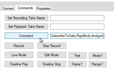
The SendMessageAndWait method under NatNetClient class is the core method for sending remote commands. This function takes in a string value of the command and sends it over to the connected Motive server each time it's called, and once the server receives the remote command, corresponding actions will be performed. Please note that only a selected set of commands can be understood by the server, which are listed under the chart below.
NatNet commands are sent via the UDP connection, 1510 port by default.
For a sample use of NatNet commands, refer to the provided .
Description
Sends a NatNet command to the NatNet server and waits for a response.
Input Parameters:
szRequest: NatNet command string, which is one of the commands listed on the below chart. If the command requires input parameters, corresponding parameters should be included in the command with comma delimiters. (e.g. string strCommand = "SetPlaybackTakeName," + TakeName;).
tries: Number of attempts to send the command. Default: 10.
timeout: Number of milliseconds to wait for a response from the server before the call times out. Default: 20.
ppServerResponse: Server response for the remote command. The response format depends on which command is sent out.
pResponseSize: Number of bytes in response
Returns:
ErrorCode, On success, it returns 0 or ErrorCode_OK.
Motive Supported NatNet Commands/Requests
Supported for Motive 3.0 or above.
Following is a general format used for the subscription command strings:
SubscribeToData,[DataType],[All or specific asset]
SubscribeByID,[DataType],[ID]
Start Recording
Framerate Query
Setting name of the recorded Take
Setting Motive Properties
NetNetClient.h header file contains declaration of the class, which is the key object used in the SDK. This object must be initialized in order to run a client application for receiving the data packets.
NatNetRequest.h header file contains a list of that can be sent over to a server application using the SendMessageAndWait function.
Force plate description contains names and IDs of the plate and its channels as well as other hardware parameter settings. Please refer to the header file for specific details.
An instance of the sDeviceDescription contains information of the data acquisition (NI-DAQ) devices. It includes information on both the DAQ device (ID, name , serial number) as well as its corresponding channels (channel count, channel data type, channel names). Please refer to the header file for specific details.
The sFrameOfMocapData can be obtained by setting up a frame handler function using the method. In most cases, a frame handler function must be assigned in order to make sure every frame is promptly processed. Refer to the provided project for an exemplary setup.
_(Deprecated)_Now, more accurate system latency values can be derived from the reported timestamp values. For more information, read through the page.
_(Deprecated)_Now, more accurate software latency values can be derived from the reported timestamp values. For more information, read through the page.
Timing information for the frame. If SMPTE timecode is detected in the system, this time information is also included. See:
The subframe value of the timecode. See: .
Given in host's high resolution ticks, this stores a timestamp value of when Motive receives the camera data. For more information, refer to the article.
Given in host's high resolution ticks, this stores a timestamp value of when tracking data is fully processed and ready to be streamed out. For more information, refer to the article.
One reconstructed 3D marker can be stored in two different places (e.g. in LabeledMarkers and in RigidBody) within a frame of mocap data. In those cases, of the marker can be used to correlate them in the client application if necessary.
Declarations for these data types are listed in the header files within the SDK. The SampleClient project included in the \NatNet SDK\Sample folder illustrates how to retrieve and interpret the data descriptions and frame data.
NatNet SDK provides a C++ helper function, , for decoding member ID and model ID of an member object. You can also decode by manually parsing the ID as demonstrated in sample.
To connect to the server, use the Initialize method from the instantiated NatNetClientML object. When calling this method, input the proper Local IP address and the Server IP address. The local IP address must match the IP address of the host PC, and the server IP address must match the address that the server is streaming onto, which is defined in the panel in Motive.
To confirm whether the client has successfully connected to the server application, let's try querying for a packet using the GetServerDescription method. If the server is connected, the corresponding server descriptions will be obtained. This method returns an value, and when successfully operated it will return a value of 0.
As explained in the page, there are two kinds of data formats included in streamed NatNet packets; one of which is Data Descriptions. In managed NatNet assembly, data descriptions for each of the assets (Marker Sets, Rigid Bodies, Skeletons, and force plates) included in the capture session is stored in a DataDescriptor class. A single capture take (or live streaming) may contain more than one assets, and respectively, there may be more than one data descriptions. For this reason, data descriptions are stored in a list format.
Now, let's obtain the tracking data from the connected server. Tracking data for a captured frame is stored in an instance of NatNetML.FrameOfMocapData. As explained in the page, every FrameOfMocapData contains tracking data of the corresponding frame. There are two approaches for obtaining frame data using the client object; by calling the GetLastFrameOfData method or by linking a callback handler function using the OnFrameReady method. In general, creating a callback function is recommended because this approach ensures that every frame of tracking data gets received.
This guide was intended for the development of the glove plugins. For instructions on setting up and using glove devices in Motive, please refer to the article.
Please reach out to for any questions or feedback on integrating glove devices.
Subscription commands work with Unicast streaming protocol only. When needed, unicast clients can send subscription commands to receive only specific data types through the data stream. This allows users to minimize the size of streaming packets. For more information, read through the page.
Below is a sample use of the NatNet commands from the application.
dllmain.cpp
This is the main entry point for the plugin interface. At startup, Motive looks for plugin DLLs located in the devices folder (C:\Program Files\OptiTrack\Motive\devices) and attempts to load them.
Once loaded, Motive calls the DLLEnumerateDeviceFactories function to enumerate device factories that will be used to instantiate the devices in Motive. Upon program exit, Motive will call the PluginDLLUnload function, where the plugin cleans itself up and unloads the SDK.
GloveDeviceBase.h
GloveDeviceBase.cpp
This file contains GloveDeviceBase class and the GloveDeviceFactory class.
GloveDeviceBase class extends the cPluginDevice and abstracts out the configurations required for a glove device.
GloveDeviceFactory class extends the cPluginDeviceFactory class and abstracts out device factory configurations required for a glove device. In Peripheral API, an instance of factory class is needed for each instance of a device.
HardwareSimulator.h
HardwareSimulator.cpp
HardwareSimulator is included to simulate a glove device. It updates the data callbacks by reading from the pre-recorded glove data in a CSV file as an example. It also includes data formats and structure types for device information and data.
ExampleGloveDevice.h
ExampleGloveDevice.cpp
ExampleGloveDevice inherits from GloveDeviceBase class to create a glove device. This class represents the actual glove device class that will be integrated.
This class mainly handles the DoCollectionThread, a separate thread used to obtain the data from the glove SDK and populate it in the analog data channels.
ExampleGloveAdapterSingleton.cpp
The ExampleGloveAdapterSingleton class is both an adapter to manage interaction with the device SDK and an aggregator that stores the glove data in its buffer.
This adapter class runs a detection thread, DoDetectionThread, that periodically checks if a new glove has been detected.
cPluginDeviceBase::kNamePropName
Default device name that will be defined for the device.
cPluginDeviceBase::kDisplayNamePropName
Display name which will be shown in the Device pane, which the user can edit.
cPluginDeviceBase::kModelPropName
Device model name.
cPluginDeviceBase::kSerialPropName
A unique device serial number. It’s critical that each device has a unique serial number. Motive references the device serial number to determine whether a new device needs to be created.
cPluginDeviceBase::kDeviceTypePropName
Type of the device. This property must be specified as: AnalogSystem::DeviceType_Glove
for all glove devices.
cPluginDeviceBase::kRatePropName
Defines the sampling rate. In the GloveDeviceExample, the glove devices will attempt to poll from the data map within the adapter class at the rate defined here.
cPluginDeviceBase::kUseDriftCorrectionPropName
This property sets whether Motive checks for frame alignment and tries to match the device frame. For glove devices, it’s best to get the latest data, so we set this to false.
cPluginDeviceBase::kOrderPropName
Order of device. In glove devices, this property is used to specify whether the glove device is the Left or Right hand. This information is used when the glove device is paired with a skeleton to make sure the correct hand gets paired.
UnitsToMillimeters
Sending this command requests current system’s measurement units, in terms of millimeters.
Sample command string:
none
float
FrameRate
Queries for the tracking framerate of the system. Returns a float value representing the system framerate.
Sample command string:
none
float
CurrentMode
Requests current mode that Motive is in. Returns 0 if Motive is in Live mode. Returns 1 if Motive is in Edit mode.
Sample command string:
none
int
StartRecording
This command initiates recording in Motive
Sample command string:
none
none
StopRecording
This command stops recording in Motive
Sample command string:
none
none
LiveMode
This command switches Motive to Live mode
Sample command string:
none
none
EditMode
This command switches Motive to Edit mode.
Sample command string:
none
None
TimelinePlay
Starts playback of a Take that is loaded in Motive
Sample command string:
none
none
TimelineStop
Stops playback of the loaded Take
Sample command string:
none
none
SetPlaybackTakeName
Set playback take
Sample command string:
Take name
None
SetRecordTakeName
Set a take name to record.
Sample command string:
Take name
None
SetCurrentSession
Set current session. If the session name already exists, Motive switches to that session. If the session does not exist, Motive will create a new session. You can use absolute paths to define folder locations.
Sample command string:
Session name
None
CurrentSessionPath
Gets the unix-style path to the current session folder as a string value, including trailing delimiter.
Sample command string:
none
string
SetPlaybackStartFrame
Set start frame
Sample command string:
Frame number
None
SetPlaybackStopFrame
Sets stop frame.
Sample command string:
Frame number
None
SetPlaybackCurrentFrame
Set current frame
Sample command string:
Frame number
none
SetPlaybackLooping
Enable or disable looping in the playback. To disable, zero must be sent along with the command.
Sample command string:
none
none
EnableAsset
Enables tracking of corresponding asset (rigid body / skeleton) from Motive
Sample command string:
Asset name
None
DisableAsset
Disables tracking of a corresponding asset (rigid body / skeleton) from Motive.
Sample command string:
Asset name
None
GetProperty
Queries the server for configured value of a property in Motive. The property name must exactly match the displayed name. This request string must have the following inputs along with the command, each of them separated by a comma.
Node name
Property name
Sample command string:
For rigid body assets, Streaming ID of rigid bodies can be used in place of the stringNodeName. For example, string command for getting name of a rigid body with streaming ID of 3 would be:
eSync:2:
Accessing the eSync 2 requires '#' to be included at the beginning of the eSync 2's serial number. If the '#' is not present, it will make the eSync 2 inaccessible. ie. GetProperty, eSync 2 #ES002005, Source Value
Node name (if applicable)
Property name
int
SetProperty
Requests Motive to configure specified properties. The property name must exactly match the respective name of setting displayed in Motive. Please refer to the Properties pane page for the list of properties. Master Rate can be used for controlling the frame rate of the camera system. For configuring camera settings remotely, use the "model #[serial]" string format.
Sample command string:
For rigid body assets, Streaming ID of rigid bodies can be used in place of the stringNodeName. For example, string command for enabling rigid body with streaming ID of 3 would be:
eSync:2:
Accessing the eSync 2 requires '#' to be included at the beginning of the eSync 2's serial number. If the '#' is not present, it will make the eSync 2 inaccessible. ie. GetProperty, eSync 2 #ES002005, Source Value
Node name. (Leave it empty if not applicable.)
Property name
Desired value
int
GetTakeProperty
Request property of a Take. You can query property of a specific Take by entering the name, or enter empty string to query the currently loaded take. Most of the properties available in the Properties: Take can be queried through this command.
Sample command string:
Take Name. Leave empty for currently loaded take.
Name of the property. See Properties: Take.
Depends on the property type.
CurrentTakeLength
Request length of current take.
Sample command string:
None
int
RecalibrateAsset
Recalibrates the asset. Returns integer indicating if command was successful. Zero if successful. Sample command string:
Asset Name
int
ResetAssetOrientation
Reorients the asset. Returns integer indicating if command was successful. Zero if successful. Sample command string:
Asset Name
int
Sample code with instructions on using Motive API functions to calibrate a camera system.
The following functions are used to complete the calibration process using the Motive API, and are presented in the order in which they would be performed. For details on specific functions, please refer to the Motive API: Function Reference page.
Auto-Masking
Auto-Masking is done directly using the AutoMaskAllCameras function. When this function is called, Motive will sample for a short amount of time and apply a mask to the camera imagers where light was detected.
Camera Mask
The CameraMask function returns the memory block of the mask, with one bit per each pixel of the mask. Masking pixels are rasterized from left to right and from top to bottom of the camera's view.
Clear Masks
The ClearCameraMask function is used to clear existing masks from the 2D camera view. It returns true when it successfully removes pixel masks.
Masking is always additive through the API unless preceded by the ClearCameraMask command.
Set Camera Mask
The SetCameraMask function is used to replace the existing camera mask for any camera. A mask is an array of bytes, one byte per mask pixel block. Returns true when masks are applied.
The CalibrationState function is used to report the current state and is typically tracked throughout the calibration process. In addition to providing status information to the operator, the Calibration state is used to determine if and when other calibration functions should be run.
OptiTrack Calibration Wands are configured with preset distances between the markers to ensure precision when calculating the position of the marker in the 3D space. For this reason, it's critical to use the SetCalibrationWand function to establish the correct wand type prior to collecting samples.
The Wand Type is identified as follows:
WandLarge
CW-500 (500mm)
WandStandard
Legacy (400mm)
WandSmall
CW-250 (250mm)
WandCustom
Custom Wand
WandMicron
Micron Series
The StartCalibrationWanding function begins the calibration wanding process, collecting samples until the StartCalibrationCalculation function is called.
The CalibrationCamerasLackingSamples function shows which cameras need more samples to obtain the best calibration. When this function returns an empty vector, then there are sufficient samples to begin calculating the calibration.
The StartCalibrationCalculation function ends the wanding phase and begins calculating the calibration from the samples collected.
Use the CalibrationState function to monitor progress through the following states:
Initialized: the calibration process has started.
Wanding: the system is collecting samples.
WandingComplete: the system has finished collecting samples. This state is set automatically when the StartCalibrationCalculation function is called.
PreparingSolver: the system is setting up the environment for the solver.
EstimatingFocals: the system is estimating the camera focal lengths.
CalculatingInitial: the system is setting up the environment to calculate the calibration.
Phase1 - 3: the system is calculating the calibration.
Phase4: the calibration calculation is finished and ready for the user to either apply or cancel.
Complete: the calibration has been applied to the cameras and the process is finished.
CalibrationError: this state occurs either when the calibration has not been started (or reset) or when an error occurs during the calibration process.
Once the Calibration State is "Phase4," use the ApplyCalibrationCalculation function to apply the newly calculated calibration to the cameras.
The CancelCalibration function stops the calibration process. Use this when a calibration error occurs or any other time you wish to stop the calibrating.
Use the CurrentCalibrationQuality function to score the calibration quality on a scale from 0-5, with 5 being the highest quality.
Set the ground plane by calling the SetGroundPlane function. When called, the camera system will search for 3-markers that resemble a calibration square. Once found, the system will use the inputted vertical offset value to configure the ground plane.
This guide covers essential points to developing a native client application using the NatNet SDK. The guideline uses sample codes in the SampleClient.cpp application in the \NatNet SDK\Sample folder, please refer to this project as an additional reference.
SDK/API Support Disclaimer
We provide developer tools to enable OptiTrack customers across a broad set of applications to utilize their systems in the ways that best suit them. Our Motive API through the NatNet SDK and Camera SDK is designed to enable experienced software developers to integrate data transfer and/or system operation with their preferred systems and pipelines. Sample projects are provided alongside each tool, and we strongly recommend the users to reference or use the samples as reliable starting points. The following list specifies the range of support that will be provided for the SDK tools:
Using the SDK tools requires background knowledge on software development; therefore, we do not provide support for basic project setup, compiling, and linking when using the SDK/API to create your own applications.
Although we ensure the SDK tools and their libraries work as intended, we do not provide support for custom developed applications that have been programmed or modified by users using the SDK tools.
Ticketed support will be provided for licensed Motive users using the Motive API and/or the NatNet SDK tools from the included libraries and sample source codes only.
The Camera SDK is a free product, and therefore we do not provide free ticketed support for it.
For other questions, please check out the NaturalPoint forums. Very often, similar development issues get reported and solved there.
a. Link the Library
When developing a native NatNet client application, NatNetLib.dll file needs to be linked to the project and placed alongside its executable in order to utilize the library classes and functions. Make sure the project is linked to DLL files with matching architecture (32-bit/64-bit).
b. Include the Header Files
After linking the library, include the header files within your application and import required library declarations. The header files are located in the NatNet SDK/include folder.
include "NatNetTypes.h"
include "NatNetClient.h"
Connection to a NatNet server application is accomplished through an instance of NatNetClient object. The client object is instantiated by calling the NatNetClient constructor with desired connection protocol (Multicast/Unicast) as its argument. Designate a desired connection protocol and instantiate the client object. In the SampleClient example, this step is done within the CreateClient function.
ConnectionType_Multicast = 0
ConnectionType_Unicast = 1
The NatNet SDK includes functions for discovering available tracking servers. While client applications can connect to a tracking server by simply inputting the matching IP address, the auto-detection feature provides easier use.The NatNet_BroadcastServerDiscovery function searches the network for a given amount of time and reports IP addresses of the available servers. The reported server information can be used to establish the connection. The NatNet_CreateAsyncServerDiscovery function continuously searches for available tracking servers by repeatedly calling a callback function. This is all demonstrated in the SampleClient application.
[C++] SampleClient.cpp : Server Discovery
Now that you have instantiated a NatNetClient object, connect the client to the server application at the designated IP address by calling the NatNetClient::Connect method.The Connect method requires a sNatNetClientConnectParams struct for the communication information; including the local IP address that the client is running on and the server IP address that the tracking data is streamed to. It is important that the client connects to appropriate IP addresses; otherwise, the data will not be received.Once the connection is established, you can use methods within the NatNetClient object to send commands and query data.
[C++] SampleClient.cpp : Connect to the Server
Now that the NatNetClient object is connected, let’s confirm the connection by querying the server for its descriptions. This can be obtained by calling the NatNetClient::GetServerDescription method and the information gets saved in the provided instance of sServerDescriptions. This is also demonstrated in the CreateClient function of the SampleClient project.
[C++] SampleClient.cpp : Request Server Description
You can also confirm connection by sending a NatNet remote command to the server. NatNet commands are sent by calling the NatNetClient::SendMessageAndWait method with supported NatNet Command as one of its input arguments. The following sample sends a command for querying the number of analog sample for each of the mocap frames. If the client is successfully connected to the server, this method will save the data and return 0.
[C++] SampleClient.cpp : Send NatNet Commands
Now that the client application is connected, data descriptions for the streamed capture session can be obtained from the server. This can be done by calling the NatNetClient::GetDataDescriptionList method and saving the descriptions list into an instance of sDataDescriptions. From this instance, the client application can figure out how many assets are in the scene as well as their descriptions.This is done by the following line in the SampleClient project:Collapse
[C++] SampleClient.cpp : Get Data Descriptions
After an sDataDescriptions instance has been saved, data descriptions for each of the assets (marker, Rigid Body, Skeleton, and force plate from the server) can be accessed from it.Collapse
[C++] SampleClient.cpp : Parsing Data Descriptions
When you are finished using the data description structure, you should free the memory resources allocated by GetDataDescription using the NatNet helper routine NatNet_FreeDescriptions().
Now that we have data descriptions, let's fetch the corresponding frame-specific tracking data. To do this, a callback handler function needs to be set for processing the incoming frames. First, create a NatNetFrameReceivedCallback function that has the matching input arguments and the return values as described in the NatNetTypes.h file:typedef void (NATNET_CALLCONV* NatNetFrameReceivedCallback)(sFrameOfMocapData* pFrameOfData, void* pUserData);The SampleClient.cpp project sets DataHandler function as the frame handler function.void NATNET_CALLCONV DataHandler(sFrameOfMocapData* data, void* pUserData)
The NatNetClient::SetFrameReceivedCallback method creates a new thread and assigns the frame handler function. Call this method with the created function and the NatNetClient object as its arguments. In the SampleClient application, this is called within the CreateClient function:
Once you call the SetDataCallback method to link a data handler callback function, this function will receive a packet of sFrameOfMocapData each time a frame is received. The sFrameOfMocapData contains a single frame data for all of the streamed assets. This allows prompt processing of the capture frames within the handler function.
When exiting the program, call Disconnect method to disconnect the client application from the server.
A guide to the functions available in the Motive API.
Please use the table of contents to the right to navigate to categories of functions. Links to the specific functions in each category are contained in the section header.
Alternately, use Ctrl + F to search the page contents.
Important Note:
Some functions are not yet included in the documentation. Please refer to the Motive API header file (MotiveAPI.h) for information on any functions that are not documented here.
In this section:
Initialize | Shutdown | BuildNumber
Initializes the API and prepares all connected devices for capturing. Initialize also loads the default profile C:\ProgramData\OptiTrack\MotiveProfile.motive. When there is a need to load the profile from a separate directory, use the LoadProfile function.
Description
This function initializes the API library and prepares all connected devices for capturing.
When using the API, this function needs to be called at the beginning of a program before using the cameras.
Returns an NPRESULT value. When the function successfully updates the data, it returns 0 (or NPRESULT_SUCCESS).
Function Input
None
Function Output
eRESULT
C++ Example
Shuts down all of the connected devices.
Description
This function closes down all connected devices and the camera library. To ensure that all devices properly shutdown, call this function before terminating an application.
When the function successfully closes down the devices, it returns 0 (or kApiResult_Success).
When calling this function, the currently configured camera calibration will be saved under the default System Calibration.cal file.
Function Input
None
Function Output
eRESULT
C++ Example
Retrieves the specific build number of the API. This is correlated with the software /// release version, but the software release version is not encoded in this value.
Description
This function returns the corresponding Motive build number.
Function Input
None
Function Output
Build number (int)
C++ Example
In this section:
Loads a Motive User Profile (.MOTIVE).
Description
Loads the default application profile file (MOTIVE), which is located in the ProgramData directory: C:\ProgramData\OptiTrack\MotiveProfile.motive
The MOTIVE file stores software configurations as well as other application-wide settings.
Returns an eRESULT integer value. If the project file was successfully loaded, it returns 0 (kApiResult_Success).
Function Input
Filename (const wchar_t)
Function Output
eRESULT
Saves the current application settings into a Profile XML file.
Description
This function saves the current configuration into an application Profile XML file.
Attaches the *.xml extension at the end of the filename.
Returns an eRESULT integer value. If the profile XML file was saved successfully, it returns 0 (kApiResult_Success).
Function Input
Filename (const wchar_t)
Function Output
eRESULT
In this section:
Update | UpdateSingleFrame | FlushCameraQueues
Processes incoming frame data from the cameras.
Description
This function updates frame information with the most recent data from the cameras and 3D processing engines.
Another use of this function is to pick up newly connected cameras. Call this function at the beginning of a program in order to make sure that all of the new cameras are properly recognized.
Update vs. UpdateSingleFrame:
In general, the Update() function is sufficient to capture frames lost when a client application stalls momentarily. This function disregards accumulated frames and serves only the most recent frame data, which means the client application will miss the previous frames.
For situations where it is critical to ensure every frame is captured and the Update() cannot be called in a timely fashion, use theUpdateSingleFrame()function ensures that the next consecutive frame is updated each time the function is called.
Returns an eRESULT integer value, depending on whether the operation was successful or not. Returns kApiResult_Successwhen it successfully updates the frame data.
Function Input
None
Function Output
eRESULT
C++ Example
Updates a single frame of camera data.
Description
Every time this function is called, it updates frame information with the next frame of camera data.
Using this function ensures that every frame of data is processed.
Update vs. UpdateSingleFrame:
In general, the Update() function is sufficient to capture frames lost when a client application stalls momentarily. This function disregards accumulated frames and serves only the most recent frame data, which means the client application will miss the previous frames.
For situations where it is critical to ensure every frame is captured and the Update() cannot be called in a timely fashion, use theUpdateSingleFrame()function ensures that the next consecutive frame is updated each time the function is called.
Returns an eRESULT value. When the function successfully updates the data, it returns 0 (or kApiResult_Success).
Function Input
None
Function Output
eRESULT
C++ Example
Flushes out the camera queues.
Description
This function flushes all queued camera frames.
In an event when you are tracking a very high number (hundreds) of markers and the application has accumulated data processing latency, you can call FlushCameraQueues() to refresh the camera queue before calling Update() for processing the frame. After calling this function, avoid calling it again until the Update() function is called and kApiResult_Success is returned.
Function Input
None
Function Output
Void
C++ Example
In this section:
LoadCalibration | LoadCalibrationFromMemory | CameraExtrinsicsCalibrationFromMemory | StartCalibrationWanding | CalibrationState | CalibrationCamerasLackingSamples | CameraCalibrationSamples | CancelCalibration | StartCalibrationCalculation |CurrentCalibrationQuality | ApplyCalibrationCalculation | SetGroundPlane | TranslateGroundPlane
Loads a Motive camera calibration file.
Description
Loads a camera calibration file (CAL).
Camera calibration files need to be exported from Motive.
Returns an eRESULT integer value. If the file was successfully loaded, it returns kApiResult_Success.
Function Input
Filename (const wchar_t)
Function Output
eRESULT
C++ Example
Loads a calibration file that was previously loaded into a memory block.
Description
This function loads a camera calibration from memory. In order to do this, the program must have a saved calibration in memory.
It assumes the pointer argument (unsigned char*) points to a memory block where calibration data is already stored. The address and size of the calibration buffer must be determined by the developer using the API.
Function Input
Buffer (unsigned char*)
Size of the buffer (int)
Function Output
eRESULT
The number of cameras read from the calibration file (int)
C++ Example
Gets camera extrinsics from a calibration file in memory.
Description
This allows for acquiring camera extrinsics for cameras not connected to system.
It returns the list of details for all cameras contained in the calibration file.
Function Input
Buffer (unsigned char*)
Size of the buffer (int)
Result
Function Output
eRESULT
Start a new calibration wanding for all cameras.
Description
This will cancel any existing calibration process.
Function Input
None
Function Output
Returns the current calibration state.
Description
Returns the current calibration state.
Function Input
None
Function Output
eCalibrationState
During calibration wanding, this will return a vector of camera indices that are lacking the minimum number of calibration samples to begin calculation.
Description
When the returned vector for this method goes to zero, call StartCalibrationCalculation() to begin calibration calculations.
Wanding samples will be collected until StartCalibrationCalculation() is called.
Function Input
None
Function Output
Vector (int)
C++ Example
Returns the number of wand samples collected for the given camera during calibration wanding.
Description
This will return the number of wand samples collected for the given camera.
Returns 0 otherwise.
Function Input
Camera index (int)
Function Output
Number of samples (int)
C++ Example
Cancels wanding or calculation and resets the calibration engine.
Description
Cancels wanding or calculation
Resets calibration engine
Function Input
none
Function Output
Exits either StartCalibrationWanding() or StartCalibrationCalculation()
Once wanding is complete, call this function to begin the calibration calculations.
Description
Starts calibration calculations after wanding.
Function Input
Boolean value
Function Output
Starts calculation
C++ Example
Retrieves the current calibration quality.
Description
This method will return the current calibration quality in the range [0-5], with 5 being best.
Returns zero otherwise
Function Input
none
Function Output
Quality on scale of 0-5 (int)
C++ Example
Call this function once CalibrationState() returns "Complete" to apply the calibration results to all cameras.
Description
Call this method to apply the calibration results to all cameras.
Function Input
none
Function Output
Apply calibration results
C++ Example
Set the ground plane using a standard or custom ground plane template.
Description
Applies a standard or custom ground plane to the calibration.
Function Input
Boolean value of useCustomGroundPlane
Function Output
Either applies custom or preset ground plane to calibration.
Translate the existing ground plane (in mm).
Description
Takes float variables to alter existing ground plane.
Function Input
X, Y, and Z values (float)
Function Output
Applies new values to existing ground plane.
In this section:
Enables or disables the NatNet streaming of the OptiTrack data.
Description
This function enables/disables the OptiTrack data stream.
This is equivalent to the Broadcast Frame Data in the Data Streaming panel in Motive.
If the operation was successful, it returns 0 (kApiResult_Success), or an error code otherwise.
Function Input
Boolean argument enabled (true) / disabled (false)
Function Output
eRESULT
C++ Example
Enables or disables data stream into VRPN.
Description
This function enables or disables data streaming into VRPN.
To stream onto VRPN, the port address must be specified. VRPN server applications run through 3883 port, which is the default port for the VRPN streaming.
Returns an eRESULT integer value. If streaming was successfully enabled, or disabled, it returns 0 (kApiResult_Success).
Function Input
True to enable and false to disable (bool)
Streaming port address (int)
Function Output
eRESULT
C++ Example
In this section:
Returns a timestamp value for the current frame.
Description
This function returns a timestamp value of the current frame.
Function Input
None
Function Output
Frame timestamp (double)
C++ Example
In this section:
MarkerCount | MarkerID | MarkerResidual | MarkerCameraCentroid
Retrieves the total number of reconstructed markers in the current frame.
Description
This function returns a total number of reconstructed 3D markers detected in the current capture frame.
Use this function to count a total number of markers, access every markers, and obtain the marker index values.
Function Input
None
Function Output
Total number of reconstructed markers in the frame (int)
C++ Example
Returns the unique identifier of a specific marker in the current frame.
Description
This function returns a unique identifier (cUID) for a given marker.
Markers have an index from 0 to [totalMarkers -1] for a given frame. In order to access unique identifier of any marker, it's index must be inputted.
The marker index value may change between frames, but the unique identifier will always remain the same.
Function Input
Marker index (int)
Function Output
Marker label (cUID)
C++ Example
Returns the residual value of a specific marker in the current frame.
Description
This function returns the residual value for a given marker indicated by the marker index.
The returned value is in millimeters.
The marker index value may change between frames, but the unique identifier will always remain the same.
Function Input
Marker index (int)
Function Output
Residual value (float)
Checks whether a camera is contributing to reconstruction of a 3D marker, and saves the corresponding 2D location as detected in the camera's view.
Description
This function evaluates whether the specified camera (cameraIndex) is contributing to point cloud reconstruction of a 3D point (markerIndex).
It returns true if the camera is contributing to the marker.
After confirming that the camera contributes to the reconstruction, this function will save the 2D location of the corresponding marker centroid in respect to the camera's view.
The 2D location is saved in the declared variable.
Function Input
3D reconstructed marker index (int)
Camera index (int)
Reference variables for saving x and y (floats).
Function Output
True / False (bool)
C++ Example
In this section:
RigidBodyCount | CreateRigidBody | SetRigidBodyProperty | ClearRigidBodies | LoadRigidBodies | AddRigidBodies | SaveRigidBodies | RigidBodyID | RigidBodyName | IsRigidBodyTracked | RemoveRigidBody | SetRigidBodyEnabled | RigidBodyEnabled | RigidBodyTranslatePivot | RigidBodyResetOrientation | RigidBodyMarkerCount | RigidBodyMarker | RigidBodyUpdateMarker | RigidBodyReconstructedMarker | RigidBodyMeanError |
Returns a total number of Rigid Bodies.
Description
This function returns a total count of Rigid Bodies defined in the project, including all tracked and untracked assets.
This function can be used within a loop to set required number iterations and access each of the Rigid Bodies.
Function Input
None
Function Output
Total Rigid Body count (int)
C++ Example
Creates a Rigid Body asset from a set of reconstructed 3D markers.
Description
This functions creates a Rigid Body from the marker list and marker count provided in its argument.
The marker list is expected to contain a list of marker coordinates in the following order: (x1, y1, z1, x2, y2, z2, …, xN, yN, zN). The x/y/z coordinates must be in respect to the Rigid Body pivot point, in meters.
Inputted 3D locations are taken as Rigid Body marker positions about the Rigid Body pivot point. If you are using MarkerX/Y/Z functions to obtain the marker coordinates, you will need to subtract the pivot point location from the global marker locations when creating a Rigid Body. This is shown in the below example. If this is not done, the created Rigid Body will have its pivot point at the global origin.
Returns an eRESULT integer value. If the Rigid Body was successfully created, it returns 0 or kApiResult_Success.
Function Input
Rigid body name (wchar_t)
User Data ID (int)
Marker Count (int)
Marker list (float list)
Function Output
eRESULT
Changes property settings of a Rigid Body.
Description
This function sets the value of a rigidbody property.
True if the property was found and the value was set
Function Input
Rigid body index (int)
Name of the property to set (std::wstring)
Value to set the property to (sPropertyValue)
Function Output
bool
Clears and removes all Rigid Body assets.
Description
This function clears all of existing Rigid Body assets in the project.
Function Input
None
Function Output
Void
C++ Example
Imports .motive files and loads Rigid Body assets from it.
Description
This function imports and loads Rigid Body assets from a saved .motive file.
.motive file contain exported Rigid Body asset definitions from Motive.
All existing assets in the project will be replaced with the Rigid Body assets from the .motive file when this function is called. If you want to keep existing assets and only wish to add new Rigid Bodies, use the AddRigidBodies function.
Returns an eRESULT integer value. It returns kApiResult_Success when the file is successfully loaded.
Function Input
Filename (const wchat_t)
Function Output
eRESULT
Loads a .motive file and adds its Rigid Body assets onto the project.
Description
This function adds Rigid Body assets from the imported .motive file to the asset list of the current project. Existing assets are not deleted.
Returns an eRESULT integer value. If the Rigid Bodies have been added successfully, it returns 0 or kApiResult_Success.
Function Input
Filename (const wchar_t)
Function Output
eRESULT
Saves all of the Rigid Body asset definitions into a .motive file.
Description
This function saves all of the Rigid Body assets from the project into a .motive file.
Returns an eRESULT integer value. It returns 0 or kApiResult_Success when successfully saving the file.
Function Input
Filename (const wchar_t)
Function Output
eRESULT
Returns the unique ID of a Rigid Body at the given index.
Description
This function returns the unique ID number of a Rigid Body.
This is different from User ID, which is a user definable ID for the Rigid Body. When working with capture data in external pipelines, this value can be used to address specific Rigid Bodies in the scene.
Function Input
Rigid body index (int)
Function Output
Unique ID number for Rigid Body
C++ Example
Returns the name for the Rigid Body at the given index.
Description
These functions are used to obtain the name of a Rigid Body.
Returns the assigned name of the Rigid Body.
Function Input
Rigid body index (int)
Function Output
Rigid body name (wconst char_t*)
C++ Example
Checks whether Rigid Body is tracked or not.
Description
Checks whether the Rigid Body is being tracked in the current frame.
Returns true if the Rigid Body is tracked.
Function Input
Rigid body index (int)
Function Output
True / False (bool)
C++ Example
Removes a Rigid Body at the given index.
Description
This function removes a single Rigid Body from a project.
Returns an eRESULT integer value. If the operation was successful, it returns 0 (kApiResult_Success).
Function Input
Rigid body index (int)
Function Output
eRESULT
C++ Example
Enables or disables tracking of a Rigid Body.
Description
This function enables or disables tracking of the selected Rigid Body.
All Rigid Bodies are enabled by default. Disabled Rigid Bodies will not be tracked, and no data will be received from it.
Function Input
Rigid body index (int)
Tracking status (bool)
Function Output
Void
C++ Example
Checks whether a Rigid Body is enabled.
Description
This function checks whether tracking of the Rigid Body is enabled or not.
The function returns true is the tracking is enabled.
Function Input
Rigid body index (int)
Function Output
True / False (bool)
C++ Example
Translates the pivot point of a Rigid Body.
Description
This function translates a Rigid Body.
3D position of a Rigid Body will be displaced in x/y/z directions by inputted amount (meters).
Translation is applied in respect to the local Rigid Body coordinate axis, not the global axis.
Returns an eRESULT integer value. If the operation is successful, returns 0 (kApiResult_Success).
Function Input
Rigid body index (int)
Translation along x-axis, in meters. (float)
Translation along y-axis, in meters. (float)
Translation along z-axis, in meters. (float)
Function Output
eRESULT
C++ Example
Resets the orientation of a Rigid Body.
Description
This function resets the orientation of the Rigid Body and re-aligns its orientation axis with the global coordinate system.
Note: When creating a Rigid Body, its zero orientation is set by aligning its axis with the global axis at the moment of creation. Calling this function essentially does the same thing on an existing Rigid Body asset.
Returns true if the Rigid Body orientation was reset.
Function Input
Rigid body index (int)
Function Input
True / False (bool)
C++ Example
Gets total number of markers in a Rigid Body.
Description
This function returns the total number of markers involved in a Rigid Body.
Function Input
Rigid body index (int)
Function Output
Total number of marker in the Rigid Body (int)
C++ Example
Retrieves the positional offset of a marker constraint from a defined rigid body.
Description
This function gets the 3D position of a solved Rigid Body marker and saves them in designated addresses. Rigid body marker positions from this function represents solved (or expected) location of the Rigid Body markers.
Note that the 3D coordinates obtained by this function are represented in respect to Rigid Body's local coordinate axis.
Function Input
Rigid body index (int)
Marker index (int)
Three declared variable addresses for saving the x, y, z coordinates of the marker (float)
Function Output
True / False (bool)
C++ Example
Changes and updates the Rigid Body marker constraint positions.
Description
This function is used to change the expected positions of a single Rigid Body marker.
Rigid body markers are expected marker positions. Read about marker types in Motive.
Function Input
Rigid body index (int)
Marker index (int)
New x-position of the Rigid Body marker in relation to the local coordinate system.
New y-position of the Rigid Body marker in relation to the local coordinate system.
New z-position of the Rigid Body marker in relation to the local coordinate system.
Function Output
Returns true if marker locations have been successfully updated.
Retrieves the reconstructed marker location for a marker constraint on a defined rigid body in the current frame.
Description
This function retrieves 3D coordinates of each expected Rigid Body marker positions in designated variable addresses.
3D coordinates are saved in respect to global coordinate system.
Function Input
Rigid body index (int)
Marker index (int)
Tracked status, True or False (bool)
Three declared variable addresses for saving x, y, z coordinates of the marker (float).
Function Output
Returns true if marker locations were found and successfully returned.
C++ Example
Returns a mean error of the Rigid Body tracking data.
Description
Returns the average distance between the constraint location and the corresponding reconstructed marker, for all constraints.
Function Input
Rigid body index (int)
Function Output
Mean error (meters)
In this section:
RigidBodyRefineStart | RigidBodyRefineSample | RigidBodyRefineState | RigidBodyRefineProgress | RigidBodyRefineInitialError | RigidBodyRefineResultError | RigidBodyRefineApplyResult | RigidBodyRefineReset |
Initiates the Rigid Body refinement process. Input the number of samples and the ID of the Rigid Body you wish to refine. After starting the process, RigidBodyRefineSample must be called on every frame to collect samples.
Description
This function is used to start Rigid Body refinement.
Function Input
Target Rigid Body ID
Sample count (int)
Function Output
Returns true if the refinement process has successfully initiated.
This function collects samples for Rigid Body refinement after calling the RigidBodyRefineStart function. Call this function for every frame within the update loop. You can check the progress of calibration by calling the RigidBodyRefineProgress function.
Description
This function collects Rigid Body tracking data for refining the definition of the corresponding Rigid Body.
Function Input
None. Samples frames for the initialized refine progress.
Function Output
Returns true if the refinement process has successfully collected a sample. This function does not collect samples if the Rigid Body is not tracked on the frame.
This function inquiries the state of the refinement process. It returns eRigidBodyRefineState enum as a result.
Description
This function queries the state of the Rigid Body refinement process. It returns an enum value for indicating whether the process is initialized, sampling, solving, complete, or uninitialized.
Function Input
None. Checks the state on the ongoing refinement process.
Function Output
Returns eRigidBodyRefineState enum value.
This function retrieves the overall sampling progress of the rigid body refinement solver.
Description
When the refinement process is under the sampling state, calling this function returns the sampling progress. It will return a percentage value representing the sampling progress with respect to the total number of samples given in the RigidBodyRefineStart parameter.
Function Input
None. Checks the progress on the ongoing refinement process.
Function Output
Returns percentage completeness of the sampling process (float).
This function returns the error value of the Rigid Body definition before the refinement and is typically called in conjunction with RigidBodyRefineResultError.
Description
Once the refinement process has reached complete stage, this function can be called along with RigidBodyRefineResultError to compare the error values from the corresponding Rigid Body definition before and after the refinement.
Function Input
None.
Function Output
Average error value of the target Rigid Body definition prior (RigidBodyRefineInitialError) and after (RigidBodyRefineResultError) the refinement.
This function returns the error value of the Rigid Body definition after the refinement.
Description
Once the refinement process has reached complete stage, this function can be called along with RigidBodyRefineInitialError to compare the error values from the corresponding Rigid Body definition before and after the refinement.
Function Input
None.
Function Output
Average error value of the target Rigid Body definition prior (RigidBodyRefineInitialError) and after (RigidBodyRefineResultError) the refinement.
This function applies the refined result to the corresponding Rigid Body definition.
Description
This function applies the refinement to the Rigid Body definition. Call this function after comparing the error values before and after the refinement using the RigidBodyRefineInitialError and RigidBodyRefineResultError functions.
Function Input
None.
Function Output
Returns true if the refined results have been successfully applied.
This function discards the final refinement result and resets the refinement process.
Description
If the final refinement result from the RigidBodyRefineResultError call is not satisfying, you can call this function to discard the result and start over from the sampling process again.
Function Input
None.
Function Output
Returns true if the refined results have been successfully reset.
In this section:
CameraCount | CameraGroupCount | CameraGroup | CameraSerial | CameraObjectCount | CameraObject | CameraObjectPredistorted | SetCameraProperty
Returns the total number of cameras connected to the system.
Description
This function returns a total camera count.
Function Input
None
Function Output
Total number of cameras (int)
C++ Example
Returns the camera group count.
Description
This function returns the total count of camera groups that are involved in the project.
This will generally return a value of two: one for the tracking cameras and one for reference cameras.
Function Input
None
Function Output
Camera group count (int)
C++ Example
Returns an index value of a camera group that a camera is in.
Description
This function takes an index value of a camera and returns the corresponding camera group index that the camera is in.
Function Input
Camera index (int)
Function Output
Camera group index (int)
C++ Example
Returns the corresponding camera's serial number as an integer.
Description
This function returns the corresponding camera's serial number.
Function Input
Camera index (int)
Function Output
Camera serial number (int)
C++ Example
Returns a total number of objects detected by a camera in the current frame.
Description
This function returns a total number of centroids detected by a camera.
A centroid is defined for every group of contiguous pixels that forms a shape that encloses the thresholded pixels.
The size and roundness filter (cCameraGroupFilterSettings) is not applied in this data.
Function Input
Camera index (int)
Function Output
Number of centroids (int)
C++ Example
Returns 2D location of the centroid as seen by a camera.
Description
This function saves 2D location of the centroid as detected by a camera's imager.
Returns true if the function successfully saves the x and y locations.
Function Input
Camera index (int)
Object index (int)
Declared variables for saving x and y (float)
Function Output
True/False (bool)
C++ Example
Retrieve the pre-distorted object location in the view of the camera.
Description
This function saves the predistorted 2D location of a centroid.
This data indicates where the camera would see a marker if there were no effects from lens distortions. For most of our cameras/lenses, this location is only a few pixels different from the distorted position obtained by the CameraObject function.
Returns true when the values are successfully saved.
Function Input
Camera index (int)
Object (centroid) index (int)
Declared variable for saving x location (float)
Declared variable for saving y location (float)
Function Output
True/False (bool)
C++ Example
Configures the value of a camera property.
Description
This function sets camera properties for a camera device specified by its index number.
A false return value indicates the function did not complete the task.
Each of the video types is indicated with the following integers. Supported video types may vary for different camera models. Please check the Data Recording page for more information on which image processing modes are available in different models.
Segment Mode: 0
Raw Grayscale Mode: 1
Object Mode: 2
Precision Mode: 4
MJPEG Mode: 6
Valid exposure ranges depend on the framerate settings:
Prime series and Flex 13: 1 ~ maximum time gap between the frames, which is approximately (1 / framerate) - 200 microseconds with about 200 microseconds gap for protection.
Valid threshold ranges: 0 - 255
Function Input
Camera index (int)
Name of the propety to set (const std::wstring&)
For more information on the camera settings, refer to the Devices pane page.
Function Output
True/False (bool)
In this section:
SetCameraGrayscaleDecimation | CameraGrayscaleDecimation | CameraIsContinuousIRAvailable | CameraSetContinuousIR | CameraContinuousIR | SetCameraSystemFrameRate | CameraSystemFrameRate |
Sets frame rate decimation ratio for processing grayscale images.
Description
This feature is available only in Flex 3 and Trio/Duo tracking bars, and has been deprecated for other camera models.
This functions sets the frame decimation ratio for processing grayscale images in a camera.
Depending on the decimation ratio, a fewer number of grayscale frames will be captured. This can be beneficial when looking to reduce the processing loads.
Supported decimation ratios: 0, 2, 4, 6, 8. When the decimation setting is set to 4, for example, a camera will capture one grayscale frame for 4 frames of the tracking data.
Returns true when it successfully sets the decimation value.
Function Input
Camera index (int)
Decimation value (int)
Function Output
True/False (bool)
C++ Example
Retrieves the configured grayscale image frame rate decimation ratio of a camera.
Description
This feature is available only in Flex 3 and Trio/Duo tracking bars, and it has been deprecated for other camera models.
This function returns grayscale frame rate decimation ratio of a camera.
Valid decimation ratios are 0, 2, 4, 8. When the decimation setting is set to 4, for example, a camera will capture one grayscale frame for 4 frames of the tracking data.
To set the decimation ratio, use the SetCameraGrayscaleDecimation function.
Grayscale images require more load on data processing. Decimate the grayscale frame images and capture the frames at a lower frame rate to reduce the volume of data.
Function Input
Camera index (int)
Function Output
Decimation ratio (int)
C++ Example
Checks if the continuous IR mode is supported.
Description
This function checks whether the continuous IR illumination mode is available in the camera model.
In the continuous IR mode, the IR LEDs will not strobe but will illuminate continuously instead.
Continuous IR modes are available only in the Flex 3 camera model and the Duo/Trio tracking bars.
Returns true if continuous IR mode is available.
Function Input
Camera index (int)
Function Output
True / False (bool)
C++ Example
Enables or disables continuous IR, if the camera supports it.
Description
This function enables, or disables, continuous IR illumination in a camera.
Continuous IR mode outputs less light when compared to Strobed (non-continuous) illumination, but this mode could be beneficial in situations where there are extraneous IR reflections in the volume.
Use the CameraIsContinuousIRAvailable function to check if the camera supports this mode.
Function Input
Camera index (int)
A Boolean argument for enabling (true) or disabling (false)
Function Output
True / False (bool)
C++ Example
Checks if the continuous IR mode is enabled.
Description
This function checks if the continuous IR mode is enabled or disabled in a camera.
Returns true if the continuous IR mode is already enabled.
Function Input
Camera index (int)
Function Output
True / False (bool)
C++ Example
Sets the camera frame rate.
Description
This function sets the master frame rate for the camera system.
Returns true if it successfully adjusts the settings.
Note that this function may assign a frame rate setting that is out of the supported range. Check to make sure the desired frame rates are supported.
Function Input
Frame rate (frames/sec)
Function Output
True/False (bool).
C++ Example
Retrieves the the current master system frame rate.
Description
This function returns the master frame rate of a camera system.
Function Input
none
Function Output
Camera frame rate (int)
C++ Example
In this section:
CameraTemperature | CameraRinglightTemperature | SetCameraAGC | SetCameraAEC | CameraImagerGainLevels
Measures the image board temperature of a camera.
Description
This function returns the temperature (in Celsius) of a camera's image board.
Temperature sensors are featured only in Prime series camera models.
Function Input
Camera index (int)
Function Output
Image board temperature (float)
C++ Example
Measures the IR LED board temperature of a camera.
Description
This function returns temperature (in celsius) of a camera's IR LED board.
Temperature sensors are featured only in Prime series camera models.
Function Input
Camera index (int)
Function Output
IR LED board temperature (float)
C++ Example
Enables or disables automatic gain control.
Description
This function enables or disables automatic gain control (AGC).
Automatic Gain Control feature adjusts the camera gain level automatically for best tracking.
AGC is only available in Flex 3 cameras and Duo/Trio tracking bars.
Returns true when the operation completed successfully.
Function Input
Camera index (int)
Enabled (true) / disabled (false) status (bool)
Function Output
True/False (bool)
C++ Example
Enables or disables automatic exposure control.
Description
This function enables or disables Automatic Exposure Control (AEC) for featured camera models.
This feature is only available in Flex 3 cameras and Duo/Trio tracking bars.
AEC allows a camera to automatically adjust its exposure setting by looking at the properties of the incoming frames.
Returns true if the operation was successful.
Function Input
Camera index (int)
A Boolean argument for enabling (true) or disabling (false) the filter.
Function Output
True/false (bool)
C++ Example
Retrieves the total number of gain levels available in a camera.
Description
This function returns a total number of available gain levels in a camera.
Different camera models may have different gain level settings. This function can be used to check the number of available gain levels.
Function Input
Camera index (int)
Function Output
Number of gain levels available (int)
C++ Example
In this section:
ClearCameraMask | SetCameraMask | CameraMask | CameraMaskInfo | AutoMaskAllCameras | SetCameraState | CameraState | CameraID | CameraFrameBuffer | CameraFrameBufferSaveAsBMP | CameraBackproject | CameraUndistort2DPoint | CameraDistort2DPoint | CameraRay | SetCameraPose | GetCamera
Clears masking from camera's 2D view.
Description
This function clears existing masks from the 2D camera view.
Returns true when it successfully removes pixel masks.
Function Input
Camera index (int)
Function Output
True / False (bool)
C++ Example
Description
This function allows a user-defined image mask to be applied to a camera.
A mask is an array of bytes, one byte per mask pixel block.
Returns true when masks are applied.
Function Input
Camera index (int)
Buffer
BufferSize
Function Output
True / False (bool)
C++ Example
Description
This function returns the memory block of the mask.
One bit per a pixel of the mask.
Masking pixels are rasterized from left to right and from top to bottom of the camera's view.
Function Input
Camera index (int)
Buffer
Buffer size
Function Output
True / False (bool)
C++ Example
Description
This function retrieves the width, height, and grid size of the mask for the camera at the given index.
One byte per pixel of the mask. Masking width * masking height gives the required size of the buffer.
Returns true when the information is successfully obtained and saved.
Function Input
Camera index (int)
Declared variables:
Masking width (int)
Masking height (int)
Masking grid (int)
Function Output
True / False (bool)
C++ Example
Auto-mask all cameras with additional masking data.
Description
Auto-mask all cameras.
This is additive to any existing masking.
To clear masks on a camera, call ClearCameraMask prior to auto-masking.
Function Input
none
Function Output
Auto masks all cameras
Sets the state for a camera.
Description
This function configures the camera state of a camera. Different camera states are defined in the eCameraState enumeration.
Returns true when it successfully sets the camera state.
Function Input
Camera index (int)
Camera state (eCameraState)
Function Output
True / False (bool)
C++ Example
Retrieves the current participation state of a camera.
Camera_Enabled
0
Camera_Disabled_For_Reconstruction
1
Camera_Disabled
2
Description
This function obtains and saves the camera state of a camera onto the declared variables.
Returns true if it successfully saves configured state.
Function Input
Camera index (int)
Declared variable for camera state (eCameraState)
Function Output
True / False (bool)
C++ Example
Returns the Camera ID.
Description
This function takes in a camera index number and returns the camera ID number.
Camera ID numbers are the numbers that are displayed on the devices.
The Camera ID number is different from the camera index number.
On Prime camera systems, Camera IDs are assigned depending on where the cameras are positioned within the calibrated volume.
On Flex camera systems, Camera IDs are assigned according to the order in which devices connected to the OptiHub(s).
Function Input
Camera index (int)
Function Output
Camera ID (int)
C++ Example
Fills a buffer with images from camera's view.
Description
This function fetches raw pixels from a single frame of a camera and fills the provided memory block with the frame buffer.
The resulting image depends on which video mode the camera is in. For example, if the camera is in grayscale mode, a grayscale image will be saved from this function call.
For obtaining buffer pixel width and height, you can use the CameraNodeImagerPixelSize property to obtain respective camera resolution.
Byte span: Byte span is the number of bytes for each row of the frame. In a case of 8-bit pixel images (one byte per pixel), the number of pixels in the frame width will equal to the byte size of the span.
Buffer pixel bit depth: Pixel bit size for the image buffer that will be stored in the memory. If the imagers on the OptiTrack cameras capture 8-bit grayscale pixels, you will need to input 8 for this input.
Buffer: make sure enough memory is allocated for the frame buffer. A frame buffer will require memory of at least (Byte span * pixel height * Bytes per pixel) bytes. For example, on a 640 x 480 image with 8-bit black and white pixels, you will need (640 * 480 * 1) bytes allocated for the frame buffer.
Returns true if it successfully saves the image in the buffer.
Function Input
Camera index (int)
Buffer pixel width (int)
Buffer pixel height (int)
Buffer byte span (int)
Buffer pixel bit depth (int)
Buffer address (unsigned char*)
Function Output
True / False (bool)
C++ Example
Saves image buffer of a camera into a BMP file.
Description
This function saves image frame buffer of a camera into a BMP file.
Video type of the saved image depends on configured camera settings
Attaches *.bmp at the end of the filename.
Returns true if it successfully saves the file.
Function Input
Camera index (int)
Filename (const wchar_t*)
Function Output
True / False (bool)
C++ Example
Obtains the 2D position of a 3D marker as seen by one of the cameras.
Description
This function reverts 3D data into 2D data. If you input a 3D location (in meters) and a camera, it will return where the point would be seen from the 2D view of the camera (in pixels) using the calibration information. In other words, it locates where in the camera's FOV a point would be located.
If a 3D marker is reconstructed outside of the camera's FOV, saved 2D location may be beyond the camera resolution range.
Respective 2D location is saved in the declared X-Y address, in pixels.
Function Input
Camera index (int)
3D x-position (float)
3D y-position (float)
3D z-position (float)
Declared variable for x and y location from camera's 2D view (float)
Function Output
Void
Removes lens distortion.
Description
This function removes the effect of the lens distortion filter and obtains undistorted raw x and y coordinates (as seen by the camera) and saves the data in the declared variables.
Lens distortion is measured during the camera calibration process.
If you want to re-apply the lens distortion filter, use the CameraDistort2DPoint function.
Function Input
Camera index (int)
Declared variables for x and y position in respect to camera's view (float)
Function Output
Void
C++ Example
Reapplies the lens distortion model.
Description
This function restores the default model for accommodating effects of the camera lens.
Note all reported 2D coordinates are already distorted to accommodate for effects of the camera lens. Use the CameraUndistort2DPoint function when working with coordinates that are undistorted .
This can be used to obtain raw data for 2D points that have been undistorted using the CameraUndistort2DPoint function.
Function Input
Camera index (int)
Declared variables for x and y position in respect to camera's view (float)
Function Input
Void
C++ Example
Obtains 3D vector from a camera to a 3D point.
Description
This function takes in an undistorted 2D centroid location seen by a camera's imager and creates a 3D vector ray connecting the point and the camera.
Use CameraUndistort2DPoint to undistort the 2D location before obtaining the 3D vector.
XYZ locations of both the start point and end point are saved into the referenced variables.
Returns true when it successfully saves the ray vector components.
Function Input
Camera index (int)
x location, in pixels, of a centroid (float)
y location, in pixels, of a centroid (float)
Three reference variables for X/Y/Z location, in meters, of the start point (float)
Three reference variables for X/Y/Z location, in meters, of the end point (float)
Function Output
True / False (bool)
C++ Example
Sets the camera's extrinsics for the OpenCV intrinsic model.
Description
This function sets camera's extrinsic (position & orientation) and intrinsic (lens distortion) parameters with values compatible with the OpenCV intrinsic model.
Returns true if the operation was successful.
Function Input
Camera index (int)
Three arguments for camera x,y,z position, in meters, within the global space (float)
Camera orientation (3x3 orientation matrix)
Function Output
True / False (bool)
Retrieves a CameraLibrary camera object from Camera SDK.
Description
This function returns a pointer to the Camera SDK's camera pointer.
While the API takes over the data path which prohibits fetching the frames directly from the camera, it is still very useful to be able to communicate with the camera directly for setting camera settings or attaching modules.
The Camera SDK must be installed to use this function.
Camera SDK libraries and the camera library header file (cameralibrary.h) must be included.
Returns Camera SDK Camera.
Function Input
Camera index (int)
Function Output
Camera SDK camera pointer (CameraLibrary::Camera)
C++ Example
In this section:
AttachCameraModule / DetachCameraModule | OrientTrackingBar |
Attaches/detaches cCameraModule instance to a camera object.
Description
This function attaches/detaches the cCameraModule class to a camera defined by its index number.
This function requires the project to be compiled against both the Motive API and the Camera SDK.
The cCameraModule class is inherited from the Camera SDK, and this class is used to inspect raw 2D data from a camera. Use this function to attach the module to a camera. For more details on the cCameraModule class, refer to the cameramodulebase.h header file from the Camera SDK.
The Camera SDK must be installed.
Function Input
Camera index (int)
cCameraModule instance (CameraLibrary::cCameraModule)
Function Output
Returns true if successful
Changes position and orientation of the tracking bars.
Description
This function makes changes to the position and orientation of the tracking bar within the global space.
Note that this function will shift or rotate the entire global space, and the effects will be reflected in other tracking data as well.
By default, the center location and orientation of a Tracking bar (Duo/Trio) determines the origin of the global coordinate system. Using this function, you can set a Tracking Bar to be placed in a different location within the global space instead of origin.
Function Input
X position (float)
Y position (float)
Z position (float)
Quaternion orientation X (float)
Quaternion orientation Y (float)
Quaternion orientation Z (float)
Quaternion orientation W (float)
Function Output
eRESULT
C++ Example
In this section:
When using the Motive API in conjunction with the Camera SDK, this method will provide access to the manager class that owns all Camera instances. From here, many system state properties can be set or queried, cameras can be queried or edited, etc.
Description
This function returns a pointer to the CameraManager instance from the Camera SDK.
If a CameraManager instance is not found, MotiveAPI will create a new one.
Camera SDK must be installed to use this function.
The version number of Motive and the Camera SDK must match.
Corresponding headers and libraries must be included in the program.
Function Input
None
Function Output
Pointer to the CameraManager instance (CameraLibrary::CameraManager*)
C++ Example
In this section:
AttachListener / DetachListener
Attaches/detaches cAPIListener onto an API project.
Description
This function attaches/detaches a cAPIListener inherited class onto an API project.
The cAPIListener class uses the C++ inheritance design model. Inherit this class into your project with the same function and class names, then attach the inherited class.
This listener class includes useful callback functions that can be overridden. Including APIFrameAvailable, APICameraConnected, APICameraDisconnected, InitialPointCloud, ApplyContinuousCalibrationResult.
Function Input
cAPIListener
Function Output
Void
In this section:
Returns the plain text message that corresponds to an eRESULT value.
Description
Returns the plain text message that corresponds to a result that an eRESULT value indicates.
Function Input
eRESULT
Function Output
Result text (const std::wstring)
C++ Example
This page lists the NatNet sample applications provided with the SDK and provides instructions for some of the samples.
Our code samples are the quickest path to get NatNet data into your application. We recommend the following steps:
Identify your application’s development/interface requirements (managed, native, etc.).
Adapt the NatNet sample code from the corresponding NatNet sample application in the samples folder into your application.
Use the API reference in the next page for additional information.
The Visual Studio solution file \Samples\NatNetSamples.sln will open and build all of the NatNet sample projects. If you are creating an application from scratch, please refer to the following sections for application specific requirements.
The following projects are located in the NatNet SDK\Samples folder.
The following sample projects utilizes NatNet SDK library for obtaining tracking data from a connected server application.
Managed: Matlab
MinimalClient
Native: C++
Sample NatNet console app that connects to a NatNet server to receive a data stream.
Contains the bare minimum code to make the NatNet connection. Good for testing connectivity.
Native: C++
Sample NatNet console app that connects to a NatNet server, receives a data stream, and writes that data stream to an ASCII file.
More robust than the MinimalClient, SampleClient provides a feature-rich template that includes everything necessary to build your own application.
Native: C++
Sample NatNet application that connects to a NatNet server, receives a data stream, and displays that data in an OpenGL 3D window.
SampleClientML
Managed: .NET (C#)
Managed: C# .NET
Simple C# .NET sample showing how to use the NatNet managed assembly (NatNetML.dll). This sample also demonstrates how to send and receive the NatNet commands.
The following sample projects do not use the NatNet SDK library. Client/Server connection is established at a low-level by creating sockets and threads within the program, and the streamed data are depacketized directly from the bit-stream syntax. The following sample approaches should be used only when the use of NatNet SDK library is not applicable (e.g., streaming into UNIX clients).
PacketClient
C++
Simple example showing how to connect to a NatNet multicast stream and decode NatNet packets directly without using the NatNet SDK.
PythonSample
Python
Sample Python code file (.py) for using Python with NatNet streaming. This sample depacketizes data directly from the bit-stream without using the library.
When working in Edit mode, pause playback in Motive to view the streamed data. Press the h key to display the NatNet help screen for additional commands.
The following samples demonstrate how to use remote triggering in Motive using the XML formatted UDP broadcast packets.
BroadcastSample
C++
XML broadcast. Sample application illustrating how to use remote record trigger in Motive using XML formatted UDP broadcast packets.
Start the OptiTrack Server (e.g. Motive) and begin streaming data via the Streaming Panel.
Start the SampleClient application from the command prompt or directly from the NatNet SDK/Samples/bin folder.
At startup, the SampleClient application searches the local network and lists the IP addresses of available tracking servers that are streaming tracking data.
Select a server address by pressing the corresponding number key. The SampleClient application will begin receiving tracking data.
Press Q at any time to quit the SampleClient application.
Start the OptiTrack Server (e.g. Motive) and begin streaming data via the Streaming Panel.
Start the MinimalClient application from the command prompt or directly from the NatNet SDK/Samples/bin folder.
Data will begin streaming once the connection is established, beginning with a list all the data descriptions in the Take, followed by individual frames of MoCap data.
If the Take is paused in Motive, the MinimalClient will remain in a listening state, waiting for Motive to stream additional data. Start the MinimalClient with playback paused if you wish to verify the data descriptions being streamed.
If the MinimalClient cannot make a connection, the application will terminate.
The Rigid Body sample (SampleClient3D) illustrates how to decode NatNet 6DOF Rigid Body and Skeleton Segment data from OptiTrack quaternion format to euler angles and display them in a simple OpenGL 3D viewer. This sample also illustrates how to associate RigidBody/Skeleton Segment names and IDs from the data descriptions with the IDs streamed in the FrameOfMocapData packet.
In Motive, load a dataset with Rigid Body or Skeleton definitions.
Enable network streaming (Data Streaming Pane -> Check Broadcast Frame Data).
Enable streaming Rigid Body data (check Stream Options -> Stream Rigid Bodies = True)
Open the Sample3D project, go to File -> Connect.
In Motive, Load a dataset with Rigid Body or Skeleton definitions.
Set the IP address to stream from (Network Interface Selection -> Local Interface).
Enable network streaming ( Data Streaming Pane -> Check Broadcast Frame Data ).
Enable streaming Rigid Body data (check Stream Options -> Stream Rigid Bodies = True).
Open the Sample3D project. Set the Client and Server IP addresses.
File -> Connect.
Edit the sample with the following properties:
IP Address: Use the IP address of the client NIC card you wish to use.
Server IP Address: IP Address of the server entered in step 2 above.
Start a NatNet server application, such as Motive (as used in our example).
Enable NatNet streaming from the Server application.
Start the WinForms sample application from the NatNet Samples folder.
Update the Local and Server IP Addresses as necessary.
Press the Connect button to connect to the server.
Select Get Data Descriptions to request and display a detailed description of the Server’s currently streamed objects.
Select a Row in the DataGrid to display that value in the graph.
Start a NatNet server application (e.g. Motive).
Enable NatNet streaming from the Server application.
Start Matlab.
Open the NatNetPollingSample.m file.
From the editor window, press Run.
This page provides instructions on how to use the subscribe commands in natNet. This feature is supported for Unicast streaming clients only.
Starting from Motive 3.0, the size of the data packets that are streamed over Unicast can be configured from each NatNet client. More specifically, each client can now send commands to the Motive server and subscribe to only the data types that they need to receive. For situations where we must stream to multiple wireless clients through Unicast, this will greatly reduce the size of individual frame data packets, and help to ensure that each client continuously receives frame data packets streamed out from Motive.
Notes
Supported for Unicast only.
Supported for Motive versions 3.0 or above.
This configuration is not necessary when streaming over a wired network since streaming packets are less likely to be dropped.
To make sure the packet size is minimized, it is recommended to clear out the filter at the beginning.
In order to set which type of tracking data gets included in the streamed packets, a filter must be set by sending subscription commands to Motive. This filter will allow client applications to receive only the desired data over a wireless Unicast network. To setup the filter, each NatNet client application(s) needs to call the method and send one of the following subscribe subscription command to the Motive server:
“SubscribeToData, [Data Type], [Name of the Asset]”
“SubscribeByID, RigidBody, [StreamingID]”
“SubscribedDataOnly”
Examples:
Type
In the Type field, you will be specifying which data type to subscribe to. The following values are accepted:
RigidBody
Skeleton
ForcePlate
Device
LabeledMarkers
MarkersetMarkers
LegacyUnlabeledMarkers
AllTypes
Name
Once the type field is specified, you can also subscribe to a specific asset by inputting the name of the rigid body. You can also input "All" or leave the name field empty to subscribe to all of the assets in that data type.
Examples
If you wish to subscribe to a Rigid Bodynamed Bat, you will be sending the following string command:
You can also subscribe to specific Skeleton also. The following command subscribes to Player Skeleton only:
To subscribe to all rigid bodies in the data stream:
Please note that Motive will not validate the presence of the requested asset, please make sure they are present on the server side.
Examples
For subscribing to a Rigid Bodywith streaming ID 3: <source>string command = "SubscribeByID,RigidBody,3";</source>
Subscription filters are additive. When needed, you can send multiple subscription commands to set multiple filters. If a subscription filter contradicts one another, the order of precedence listed (high-to-low) below is followed:
Filter Precedence Order:
Specified asset, either by name or the streaming ID.
Specified data type, all
Specified data type, none
All types, all
All types, none
Unspecified – respects Motive settings.
To clear the subscription filter, a client application can send an empty subscribe command OR disconnect and reconnect entirely. It’s suggested to clear the filter at the beginning to make sure the client application(s) is subscribing only to the data that’s necessary.
If you subscribe to a Rigid Bodywith a specific name or specific streaming ID, commands for unsubscribing to all will not unsubscribe to that specific object. To stop receiving data for a particular object, whether it's a Rigid Bodyor a Skeleton, the client will need to send an unsubscribe command for that specific object also.
This page provides detailed information on the definition of latency measurements in Motive and the NatNet SDK streaming protocol.
The OptiTrack systems combine state of art technologies to provide swift processing of captured frame data in order to accomplish 3D tracking in real-time. However, minimal processing latencies are inevitably introduced throughout processing pipelines. For timing-sensitive applications, these latency metrics can be monitored from the of Motive or in the streaming protocol.
The latency in an OptiTrack system can be broken down in the the components described in the image below.
With Motive 3.0+ PrimeX cameras now can go at up to 1000 Hz. In order to do this the image size processes reduces as the frequency goes over the native frame rate for a particular camera. Because less camera data is being process at higher rates, the latency also decreases. The image below shows how the latency changed from the previous image by going from 240 Hz to 500 Hz with PrimeX 13 cameras.
Example frame rates vs the latency added by the camera for a PrimeX 41 camera....
(Available for Ethernet camera systems only) This value represents current system latency. This is reported under the Status Panel, and it represents the total time taken from when the cameras expose and when the data is fully solved.
It represents the amount of time it takes Motive to process each frame of captured data. This includes the time taken for reconstructing the 2D data into 3D data, labeling and modeling the trackable assets, displaying in the viewport, and other processes configured in Motive.
This is available only in NatNet version 3.0 or above.
Exemplary latency calculations are demonstrated in the SampleClient project and the WinFormSample project. Please refer to these sources to find more about how these latency values are derived.
Timestamp of Point A: sFrameOfMocapData::CameraMidExposureTimestamp. Available for Ethernet cameras only (Prime / Slim13E).
Timestamp of Point B: sFrameOfMocapData::CameraDataReceivedTimestamp.
Timestamp of Point D: sFrameOfMocapData::TransmitTimestamp.
System Latency (NatNet)
(Available for Ethernet camera systems only)
This is the latency introduced by both hardware and software component of the system. This represents the time difference between when the cameras expose and when the capture data is all processed and prepared to be streamed out.
System Latency may not always be available for all system configurations. Thus, it is suggested to enclose this calculation within a conditional statement.
Software Latency (NatNet)
This value needs be derived from the NatNet streaming protocol.
This latency value represents the time it takes Motive to process the captured data and have it fully ready to be streamed out. This measurement also covers the data packaging time.
This can be derived by subtracting two timestamp values that are reported in NatNet:
In the older versions of NatNet, the software latency was roughly estimated and reported as fLatency data, which is now deprecated. The derived software latency described in this can be used to replace the fLatency values.
Transmission Latency
The transmission latency represents the time difference between when Motive streams out the packaged tracking data and when the data reaches the client application(s) through a selected network.
Client Latency
The client latency is the time difference between when the cameras expose and when the NatNet client applications receive the processed data. This is basically the total time it takes for a client application(s) to receive the tracking data from a mocap system.
In previous versions of Motive (prior to 2.0), the only reported latency metric was the software latency. This was an estimation of the software latency derived from the sum of the processing times taken from each of the individual solvers in Motive. The latency calculation in Motive 2.0 is a more accurate representation and will be slightly larger by comparison than the latency reported in the older versions.
Sample MATLAB code file (.m) for using MATLAB with the NatNet managed assembly (NatNetML.dll) using the provided class. Works in Matlab version 2014 or above.
Sample NatNet C# console application that connects to a NatNet server on the local IP address, receives data stream, and outputs the received data. Note: must be set to false.
The SubscribeToData command allows you set up the filter so that NatNet client receives only the data types that it has subscribed to. Using this command, each client can subscribe to specific data types included in NatNet data packets. To set up the filter, the following string command must be sent to the Motive server using method:
Another option for subscribing to a specific data is by providing the asset ID. This works only with rigid bodies that has values. This command may be easier to use when streaming to multiple clients with many rigid bodies.
For quickly testing the NatNet commands, you can utilize the program provided in the NatNet SDK package. This program has commands tab which can be used for calling the SendMessageAndWait method. Using this input field, you can test the command string to test out its results.
This measurement is reported in the in Motive.
This measurement is reported in the in Motive.
Please note that this does not include the time it takes for Motive to convert the solved data into the NatNet streaming protocol format. This conversion accounts for a slight additional latency (≈ 0.2 ms) which is only reflected in the software latency value reported via , therefore resulting in a small delta between the software latency values as reported by Motive and NatNet.
Latencies from the point cloud reconstruction engine, Rigid Body solver, and Skeleton solver are reported individually on the in Motive.
In NatNet 3.0, new data types have been introduced to allow users to monitor measured timestamps from specific points in the pipeline. From received in the NatNet client applications, the following timestamps can be obtained:
Refer to the page or the NatNetTypes.h file for more information
These timestamps are reported in “ticks” that are provided by the host computer clock. When computing latencies, you need to divide the timestamp values by the clock frequency in order to obtain the time values in seconds. The clock frequency is included in the server description packet: sServerDescriptionPacket::HighResClockFrequency. To calculate the time that has elapsed since a specific timestamp, you can simply call the method, passing the desired timestamp as its input. Using clock synchronization between the client and server, this will return the time in seconds since the corresponding timestamp.
This value needs to be derived from the streaming protocol by subtracting two timestamp values that are reported in NatNet:
This value must be derived from the streaming protocol.
This value can be obtained by calling the using sFrameOfMocapData::TransmitTimestamp as the input.
This value must be derived from the streaming protocol.
This value can be obtained by calling the method using sFrameOfMocapData::CameraMidExposureTimestamp as the input.
20 Hz - 180 Hz
5.56 ms
240 Hz
4.17 ms
360 Hz
2.78 ms
500 Hz
2.00 ms
1000 Hz
1.00 ms
A
This point represents the center of the camera exposure window
B
This is when Motive receives the 2D data from the cameras
C
This is when tracking data is fully solved in Motive.
D
This is when the tracking data is all processed and ready to be streamed out.
E
This is when the Client application receives the streamed tracking data.