Loading...
Loading...
Loading...
Loading...
Loading...
Loading...
Loading...
Loading...
Loading...
Loading...
Important Note
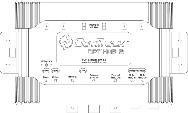
Please note that the OptiHub2 is not designed for precise synchronization with external devices. It is used to provide only a rough synchronization to a trigger event on the input/output signal. Using an OptiHub2, there will be some amount of time delay between the trigger events and the desired actions, and for this reason, the OptiHub2 is not suitable for the precisely synchronizing to an external device. To accomplish such synchronization, it is recommended to use the eSync 2 instead along with an Ethernet camera system.
By modifying the device properties of the OptiHub, users can customize the sync configurations of the camera system for implementing external devices in various sync chain setups. This page directly lists out the properties of the OptiHub. For general instructions on customizing sync settings for integrating external devices, it is recommended to read through the External Device Sync Guide: OptiHub 2 guide.
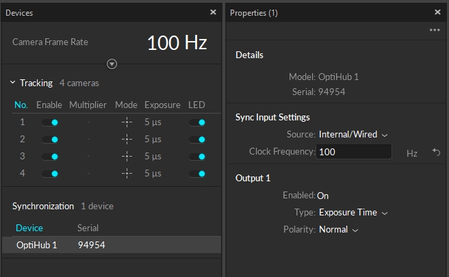
While the OptiHub is selected under the Devices pane, use the Properties pane to view and configure its properties. By doing so, users can set the parent sync source for the camera system, configure how the system reacts to input signals, and also which signals to output from the OptiHub for triggering other external acquisition devices.
This option is only valid if the Sync Input: Source is set to Internal Sync. Controls the frequency in Hertz (Hz) of the OptiHub 2's internal sync generator. Valid frequency range is 8 to 120 Hz.
This option is only valid if the Sync Input: Source is set to Sync In or USB Sync_. Controls synchronization delay in microseconds (us) between the chosen sync source signal and when the cameras are actually told to expose. This is a global system delay that is independent of, and in addition to, an individual camera's exposure delay setting. Valid range is 0 to 65862 us, and should not exceed one frame period of the external signal._
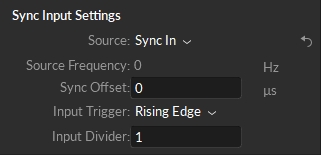
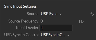
To setup the sync input signals, first define a input Source and configure desired trigger settings for the source:
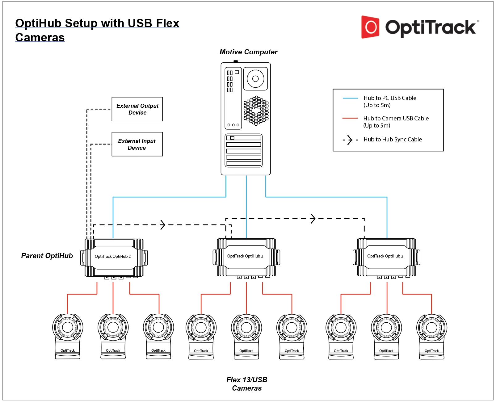
Internal/Wired sets the OptiHub 2 as the sync source. This is the default sync configuration which uses the OptiSync protocol for synchronizing the cameras. The Parent OptiHub 2 will generate an internal sync signal which will be propagated to other (child) OptiHub 2(s) via the Hub Sync Out Jack and Hub Sync In Jack. For V100:R1(legacy) and the Slim 3U cameras, Wired Sync protocol is used. In this mode, the internal sync signal will still be generated but it will be routed directly to the cameras via daisy-chained sync cables.
Sync In sets an external device as the sync source.
USB Sync sets an external USB device as the sync source. This mode is for customers who use the Camera SDK development kits and would like to have their software trigger the cameras instead. Using the provided API, the OptiHub 2 will be send the trigger signal from the PC via the OptiHib 2's USB uplink connection to the PC.
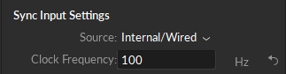
The Internal/Wired input source uses the OptiHub 2's internal synchronization generator as the main sync source. You can modify the synchronization frequency for both Wired and OptiSync protocol under the Synchronization Control section. When you adjust the system frame rate from this panel, the modified frame rate may not be reflected on the Devices pane. Check the streaming section of the status bar for the exact information.
This option is only valid if the Sync Input: Source is set to Internal Sync. Controls the frequency in Hertz (Hz) of the OptiHub 2's internal sync generator, and the this frequency will control the camera system frame rate. Valid frequency range is 8 to 120 Hz.
The Sync In input source setting uses signals coming into the input ports of the OptiHub 2 to trigger the synchronization. Please refer to External Device Sync Guide: OptiHub 2 page for more instructions on this.
Detects and displays the frequency of the sync signal that's coming through the input port of the parent OptiHub 2, which is at the very top of the RCA sync chain. When sync source is set to Sync In, the camera system framerate will be synchronized to this input signal. Please note that OptiHub 2 is not designed for precise sync, so there may be slight sync discrepancies when synchronizing through OptiHub 2.
Manually adds global sync time offset to how camera system reacts to the received input signal. The input unit is measured in microseconds.
Can select from Either Edge, Rising Edge, Falling Edge, Low Gated, or High Gated signal from the connected input source.
Allows a triggering rate compatible with the camera frame rate to be derived from higher frequency input signals (e.g. 300Hz decimated down to 100Hz for use with a V100:R2 camera). Valid range is 1 (no decimation) to 15 (every 15th trigger signal generates a frame).
(The camera system will be the child) sets an external USB device as the sync source. This mode is for customers who use the Camera SDK development kits and would like to have their software trigger the cameras instead. Using the provided API, the OptiHub 2 will be send the trigger signal from the PC via the OptiHib 2's USB uplink connection to the PC.
Detects and displays the frequency of the parent source.
Allows the user to allow or block trigger events generated by the internal sync control. This option has been deprecated for use in the GUI. Valid options are Gate-Open and Gate-Closed.
Allows a triggering rate compatible with the camera frame rate to be derived from higher frequency input signals (e.g. 360Hz decimated down to 120Hz for use with a Flex 13 camera). Valid range is 1 (no decimation) to 15 (every 15th trigger signal generates a frame).}}
Either Edge
Uses either the rising or falling edge of the pulse signal.
Rising Edge
Uses the rising edge of the pulse signal.
Falling Edge
Uses the falling edge of the pulse signal.
High Gated
High Gated mode triggers when the input signal is at a high voltage level, but stops triggering at a low voltage level.
Low Gated
Low Gated mode triggers when the input signal is at a low voltage level, but stops triggering at a high voltage level.
Sync signals can also be sent out through the output ports of the OptiHub 2 to child devices in the synchronization chain. Read more: External Device Sync Guide: OptiHub 2.
Selects condition and timing for a pulse to be sent out over the External Sync Out jack. Available Types are: Exposure Time, Pass-Through, Recording Level, and Recording Pulse.
Exposure Time
Outputs a pulse signal when the cameras expose.
Pass-Through
Passes the input signal to the output.
Recording Gate
Outputs a constant high level signal while recording. Other times the signal is low. (Referred as Recording Level in older versions).
Gated Exposure Time
Outputs a pulse signal when the cameras expose during a recording only. (Referred as Recording Pulse in older versions).
Polarity
Selects output polarity of External Sync Out signal. Valid options are: Normal and Inverted. Normal signals are low and pulse high and inverted signals are high and pulse low.
An in-depth look at the properties available for Rigid Bodies.
Rigid body properties determine how the corresponding Rigid Body asset is tracked and displayed in the 3D Viewport. This page covers the properties specific to Rigid Bodies. For general information on using and customizing the Properties pane, see the Properties Pane page. For detailed descriptions of properties for other asset types or devices, please see the following pages:
Select a Rigid Body asset in the Assets pane or in the 3D viewport, and the corresponding properties will be listed under the Properties pane. These properties can be modified both in Live and Edit mode. Default creation properties are listed under the Assets Settings.
Advanced Settings
Use the Edit Advanced option to customize which settings are in the Advanced Settings category and which appear in the standard view, to show only the settings that are needed specifically for your capture application.
The following items are available in the General Properties section. Properties are Standard unless noted otherwise.
Enter a custom name for the Rigid Body. The default name is "Rigid Body X," where X is the Rigid Body ID. The Asset Name can also be changed by right-clicking the Rigid Body in the Assets pane.
Enable or Disable tracking of the selected Rigid Body. A disabled Rigid Body will not be tracked, and its data will not be included in the exported or streamed tracking data or displayed in the 3D Viewport.
To hide the markers associated with a disabled asset in the 3D Viewport:
Select Markers -> Hide for Disabled Assets.
An optional text field for storing additional information about the Rigid Body. The data in the Notes field is not included when exporting the asset to a CSV file.
Sets the minimum number of markers that must be tracked and labeled in order for a Rigid Body asset, or each Skeleton bone, to be booted or first tracked.
Sets the minimum number of markers that must be tracked and labeled in order for a Rigid Body asset, or each Skeleton bone, to continue to be tracked after the initial boot.
Sets the minimum number of active markers that must be tracked and labeled for Rigid Bodies to be booted or first tracked. For more information on working with Active Markers, see the pages Active Marker Tracking and IMU Sensor Fusion.
Asset Scale (Advanced Setting)
Increase or decrease the size of the Rigid Body bone by scaling the asset. By default, the Asset Scale is set to 100%.
Deflection Ratio (Advanced Setting)
Allows the asset to deform more or less to accommodate markers that don't fit the model. High values will allow assets to fit onto markers that don't match the model as well.
User definable ID for the selected Rigid Body. When working with capture data in the external pipeline, this value can be used to address specific Rigid Bodies in the scene.
The following items are available in the Visuals section. Properties are Standard unless noted otherwise.
Set the axis with which the bone should be aligned. The coordinate at the end of the bone is expected to be on this axis.
Default Bone Length (Advanced Setting)
Set the offset (in mm) from the bone to the end effector, along the major axis, for bones that do not have child bones.
Bone Diameter (Advanced Setting)
Set the diameter of the bone (in mm).
Label
Display the Rigid Body name in the 3D Perspective View. When selected, a small label in the same color as the Rigid Body will appear over the centroid.
Display a label with the status of the Rigid Body's IMU in the 3D Perspective View: IMU Working [Optical] %. If the asset Label is enabled, the IMU state is added after the asset name.
The Optical status indicates whether the Minimum Markers to Continue threshold has been met (Optical), exceed (Good Optical) or is missing. (no optical).
The % status denotes the amount of IMU packets that an IMU Tag is successfully delivering for every 100 frames.
Display the marker sticks and bone constraint lines in the 3D Perspective View.
Set the color of the selected Rigid Body in the 3D Perspective View. Click the box to bring up the color picker:
Display a visual of the bone, or pivot point, of the Rigid Body in the 3D Viewport. The shape of the bone indicates whether the asset is solved or unsolved.
Set the color of the bone in the 3D Perspective View. By default, the bone uses the same color as the Rigid Body asset.
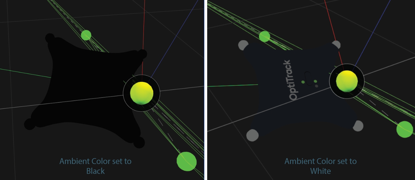
Display the Rigid Body's local coordinate axes. This option can be useful in visualizing the orientation of the Rigid Body, and for setting orientation offsets. The setting is enabled in the images above.
Show the history of the Rigid Body’s position in the Perspective view. When enabled, the option to set the history length becomes available.
Display degrees of freedom, position and orientation, for each bone pivot.
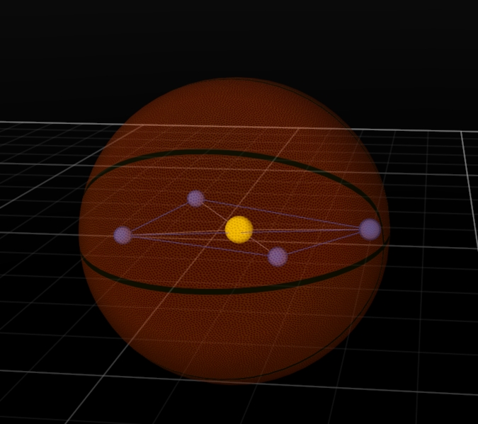
Show the Marker Constraints as transparent spheres on the Rigid Body. Marker Constraints are the expected marker locations according to the Rigid Body solve.
Show lines between labeled Rigid Body markers and corresponding expected marker locations. This helps to visualize the offset distance between actual marker locations and the Marker Constraints.
Display a dotted line to connect each Marker Constraint to the Rigid Body bone pivot.
Sets the opacity of an attached object. An OBJ file typically comes with a corresponding MTL file which defines its properties, and the transparency of the object is defined within these MTL files. The Opacity value under the Rigid Body properties rescales the loaded property. In other words, you can set the transparency in the MTL file and rescale it using the Opacity property in Motive.
Attach a valid geometric model to the rigid body to display in the the 3D Viewport. Sphere, box, cylinder, and bone segment shapes are built-in; to use your own geometric model, select Custom Model. This will open the Attached Geometry field.
The Attached Geometry field becomes available whenever Custom Model is selected for the Rigid Body geometry.
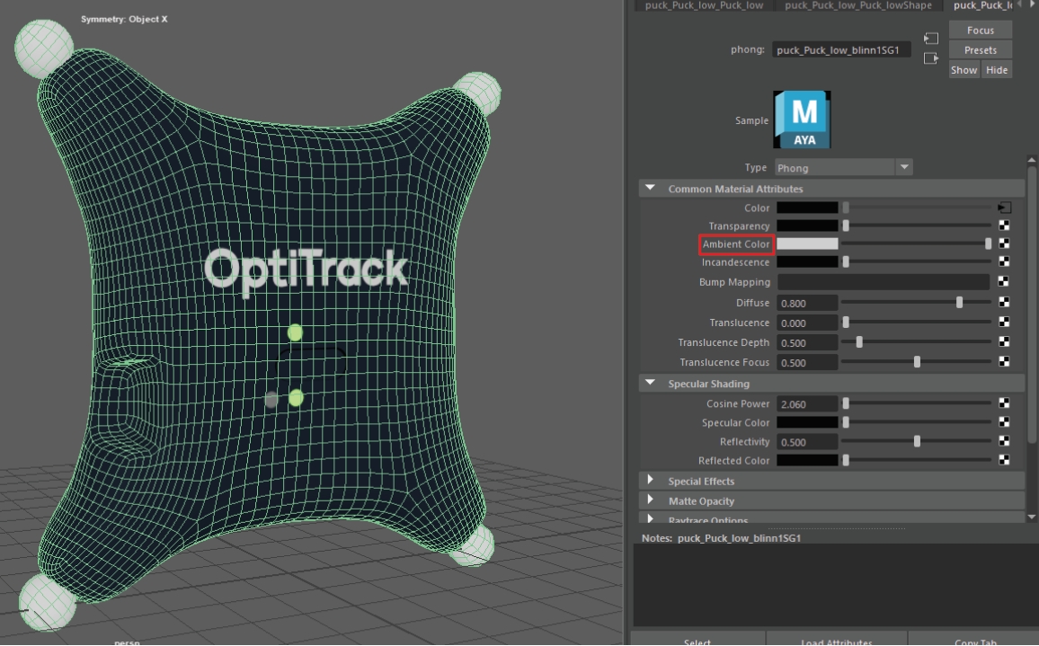
Click the folder to the right of the field to browse to the OBJ or FBX file to replace the Rigid Body. Properties configured in the corresponding MTL files alongside the OBJ file will be loaded as well.
Whenever a geometric model is attached, settings to adjust the scale, location, and orientation (Pitch, Yaw, and Roll) are available.
If you are exporting an OBJ file from Maya, make sure the Ambient Color setting is set to white upon export. If this color is set to black, it will remove textures when the Rigid Body is deselected.
The Bone is the pivot point of a Rigid Body. Unlike Skeletons or Trained Markersets, Rigid Bodies are comprised of a single bone.
The Parent bone is the first bone in a Bone Chain, as used in Skeleton and Trained Markerset assets.
A Child bone connects to the parent bone in a Bone Chain, as used in Skeleton and Trained Markerset assets. For Rigid Bodies, Motive displays one of the asset's marker labels.
Used for Skeleton and Trained Markerset assets to identify bone segments. For Rigid Bodies, this value is set to None.
Euler angle rotation order used for calculating the bone hierarchy.
Enter values along one of the axis to reorient the Rigid Body coordinate axis.
Enter values along one of the axis to move the Rigid Body pivot point.
Apply double exponential smoothing to translation and rotation of the Rigid Body. Increasing this setting may help smooth out noise in the Rigid Body tracking, but excessive smoothing can introduce latency. The default value is 0 (disabled).
Compensate for system latency when tracking the corresponding Rigid Body by predicting its movement into the future. Please note that using higher values may impact the tracking stability. The default value is 0 (disabled).
When needed, you can damp down translational tracking of a Rigid Body bone on the selected axis.
You can also damp down rotational tracking of a Rigid Body.
When using Rotation Damping, select whether to apply changes to a selected axis or to all.
Active devices such as CinePucks and Pucks are often equipped with an Inertial Measurement Unit (IMU) that increases the accuracy of tracking when fused with the rigid body. To learn more about pairing IMUs to Rigid Bodies, read the IMU Sensor Fusion page.
To view properties related to the IMU, select the Active Tag paired to the Rigid Body in the Devices pane.
The Uplink ID is a sequential number assigned to the Tag or Puck when pairing it to a Base Station. This number is unique to each device attached to the Base Station. It is the second component of the Active Tag name in the Devices Pane.
The Radio frequency communication channel used to communicate with the Base Station. This is the first component of the Active Tag name in the Devices Pane.
IMU properties are read-only in Motive.
All Tags/Pucks are shipped pre-configured for every set of devices in the same order, with no Label overlap.
The cases when you would need to reconfigure the active components are:
When you have purchased new Tags/Pucks to add to a system from a previous order.
When there is a need to change the RF communication channel to avoid interference.
Use the Active Batch Programmer if you need to update any of these properties.
An in-depth look at the properties available for Cameras.
Camera properties determine how and what a camera captures when recording. These settings can be configured to optimize your capture application.
This page covers the properties specific to cameras. For general information on using and customizing the Properties pane, see the Properties Pane page. For detailed descriptions of properties for various asset types or other devices, please see the following pages:
Advanced Settings
The Properties pane contains advanced settings that are hidden by default. To access these settings, click the button in the top right corner.
Use the Edit Advanced option to customize which settings are in the Advanced Settings category and which appear in the standard view, to show only the settings that are needed specifically for your capture application.
Changes made to camera settings through the Properties Pane apply to all selected cameras.
This section provides basic information about the selected camera(s). Properties are Standard unless noted otherwise. Most are read-only.
Displays the name of the selected camera type, e.g., Prime 13, Slim 3U, etc.
Displays the model number of the selected camera, where applicable.
Sub-Model (Advanced)
Displays the sub-model number of the selected camera, where applicable..
Displays the camera serial number.
Displays the camera number assigned by Motive.
Camera numbering is determined by the Camera ID setting on the General tab of Motive's settings panel. To open up the number field for editing, set the Camera ID to Custom.
Displays the focal length of the camera's lens.
Displays the x/y/z coordinates of the camera in relation to the global origin.
Displays the orientation (pitch/yaw/roll) of the camera in relation to the global origin.
Displays the resolution of the camera's image sensor, in pixels.
The following items are available in the General Properties section. Properties are Standard unless noted otherwise.
A camera must be enabled to record data and contribute to the reconstruction of 3D data, if recording in object mode. Disable a camera if you do not want it included in the data capture.
This setting determines whether the selected camera contributes to the real-time reconstruction of the 3D data.
When this setting is disabled, Motive continues to record the camera's 2D frames into the capture file, they are just not processed in the real-time reconstruction. A post-processing reconstruction pipeline allows you to obtain fully contributed 3D data in Edit mode.
For most applications, it's fine to have all cameras contribute to the 3D reconstruction engine. In a system with a high camera-count, this can slow down the real-time processing of the point cloud solve and result in dropped frames. Resolve this by disabling some cameras from real-time reconstruction and using the collected 2D data later in post-processing.
Shows the frame rate of the camera. The camera frame rate can be changed from the Devices pane.
Shows the rate multiplier or divider applied to the master frame rate. The master frame rate depends on the sync configuration.
Sets the amount of time that the camera exposes per frame. Exposure value is measured in scanlines for tracking bars and Flex3 series cameras, and in microseconds for Flex13, S250e, Slim13E, and Prime Series cameras. The minimum and maximum values allowed depend on both the type of camera and the frame rate.
Higher exposure allows more light in, creating a brighter image that can increase visibility for small and dim markers. However, setting the exposure too high can introduce false markers, larger marker blooms, and marker blurring, all of which can negatively impact marker data quality.
Defines the minimum brightness for a pixel to be recognized by a camera, with all pixels below the threshold ignored.
Increasing the threshold can help filter interference by non-markers (e.g. reflections and external light sources), while lowering the threshold can allow dimmer markers to be seen by the system (e.g. smaller markers at longer distances from the camera).
Camera partitions create the ability to have several capture volumes (multi-room) tied to a single system. Continuous Calibration collects samples from each partition and calibrates the entire system even when there is no camera overlap between spaces.
This setting enables the IR LED ring on the selected camera. This setting must be enabled to illuminate the IR LED rings to track passive retro-reflective markers.
If the IR illumination is too bright for the capture, decrease the camera exposure setting to decrease the amount of light received by the imager, dimming the captured frames.
Select from 4 video types:
Tracking: Tracking modes capture the 2D marker data used in the reconstruction of 3D data.
Object mode: Performs on-camera detection of centroid location, size, and roundness of the markers, and sends respective 2D object metrics to Motive to calculate the 3D data. Recommended as the default mode for recording.
Precision mode: Performs on-camera detection of marker reflections and their centroids and sends the respective data to Motive to determine the precise centroid location. Precision mode is more processing intensive than Object mode.
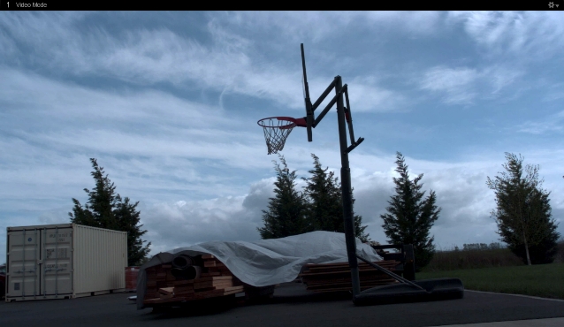
Reference Modes: Reference modes capture grayscale video as a visual aid during the take. Cameras in these modes do not contribute to the reconstruction of 3D data.
Grayscale: Raw grayscale is intended for aiming and monitoring the camera views and diagnosing tracking problems and includes aiming crosshairs by default. Grayscale video cannot be exported.
MJPEG: A reference mode that captures grayscale frames, compressed on-camera for scalable reference videos. MJPEG videos can be exported along with overlay information such as markers, rigid bodies, and skeleton data.
Sets the camera to view either visible or IR spectrum light on cameras equipped with a Filter Switcher. When enabled, the camera captures in IR spectrum, and when disabled, the camera captures in the visible spectrum.
Infrared Spectrum should be selected when the camera is being used for marker tracking applications. Visible Spectrum can optionally be selected for full frame video applications, where external, visible spectrum lighting will be used to illuminate the environment instead of the camera’s IR LEDs. Common applications include reference video and external calibration methods that use images projected in the visible spectrum.
Sets the imager gain level for the selected camera. Gain settings can be adjusted to amplify or diminish the brightness of the image.
This setting can be beneficial when tracking at long ranges. However, note that increasing the gain level will also increase the noise in the image data and may introduce false reconstructions.
Before changing the gain level, we recommend adjusting other camera settings first to optimize image clarity, such as increasing exposure and decreasing the lens f-stop.
Shows whether the selected camera has been calibrated. This property does not indicate the quality of the calibration.
When enabled, the estimated field of view (FOV) of the selected camera is shown in the perspective viewport. When the camera is selected, the lines display in yellow. When the camera is not selected, the lines display in cyan.
Frame delivery information is used to determine how fast a camera is delivering its frame packets. When enabled, the frame delivery information is shown in the Camera views.
This setting can also be enabled by right-clicking a camera in the Cameras view or in the 3D Viewport and selecting Frame Delivery Visual.
Aiming Crosshairs are controlled globally through Motive's general settings. To see and change those settings:
In the Aim Assist section of the General tab, select a value for Aiming Crosshairs:
None
Grayscale Only (default)
All Modes
Prime color cameras also have the following additional properties that can be configured:
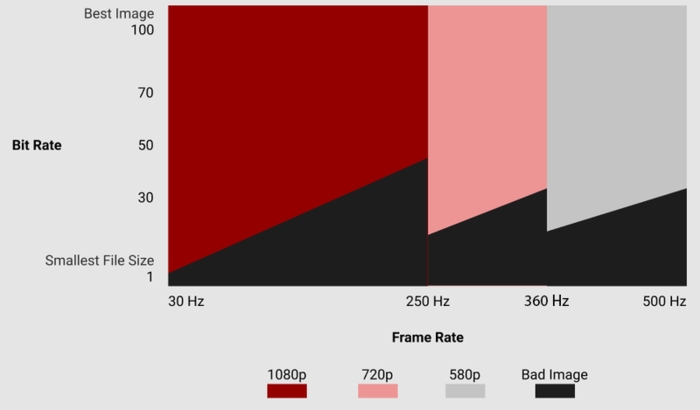
Default: 1920 x 1080
This property sets the resolution of the images captured by the selected camera.
You may need to reduce the maximum frame rate to accommodate the additional data produced by recording at higher resolutions. The table below shows the maximum allowed frame rates for each respective resolution setting.
960 x 540 (540p)
500 FPS
1280 x 720 (720p)
360 FPS
1920 x 1080 (1080p)
250 FPS
Default: Constant Bit Rate.
This property determines how much the captured images will be compressed.
Constant Bit-Rate
In the Constant Bit-Rate mode, Prime Color cameras vary the degree of image compression to match the data transmission rate given under the Bit Rate settings. At a higher bit-rate setting, the captured image will be compressed less. At a lower bit-rate setting, the captured image will be compressed more to meet the given data transfer rate. Compression artifacts may be introduced if it is set too low.
The Constant Bit-Rate mode is used by default and recommended because it is easier to control the data transfer rate and efficiently utilizes the available network bandwidth.
Variable Bit-Rate
The Variable Bit-Rate setting keeps the amount of the compression constant and allows the data transfer rate to vary. This mode is beneficial when capturing images with objects that have detailed textures because it keeps the amount of compression consistent on all frames. However, this mode may also cause dropped frames if the camera needs to compress highly detailed images, spiking the data transfer rate, which may overflow the network bandwidth as a result. For this reason, we recommend using the Constant Bit-Rate setting in most applications.
The compression property sets the percentage (100%) of the maximum data transmission speed to allocate for the camera.
Default: 100 MB/s
Available only while using Constant Bit-rate Mode
The bit-rate setting determines the selected color camera's output transmission rate.
The maximum data transmission speed that a Prime color camera can output is 100 megabytes per second (MB/s). At this setting, the camera will capture the best quality image, however, it could overload the network if there isn't enough bandwidth to handle the transmitted data.
Since the bit-rate controls the rate of data each color camera outputs, this is one of the most important settings to adjust when configuring the system.
When a system is experiencing 2D frame drops, one of the following system requirements is not being met:
Network bandwidth
CPU processing speed
RAM/disk memory
Decreasing the bit-rate in such cases may slow the data transmission speed of the color camera enough to resolve the problem.
While the image quality increases at a higher bit-rate setting, this also results in larger file sizes and possible frame drops due to data bandwidth bottlenecks. The desired result may differ depending on the capture application and its intended use. The below graph illustrates how the image quality varies depending on the camera frame rate and bit-rate settings.
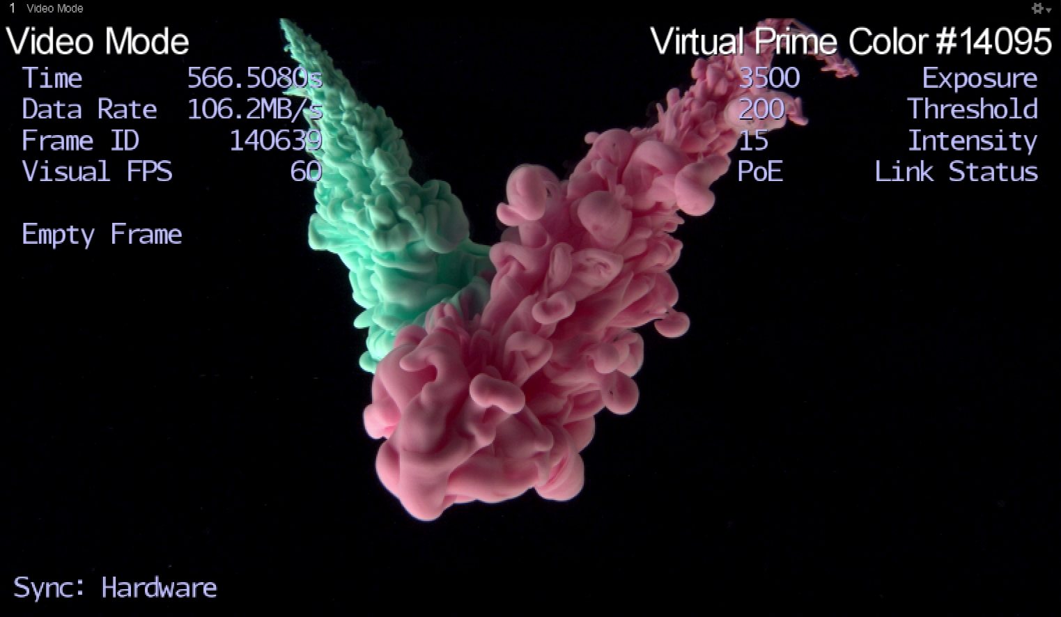
Tip: Monitoring data output from each camera
Default : 24
Gamma correction is a non-linear amplification of the output image. The gamma setting will adjust the brightness of dark pixels, mid-tone pixels, and bright pixels differently, affecting both brightness and contrast of the image. Depending on the capture environment, especially with a dark background, you may need to adjust the gamma setting to get best quality images.
The Properties pane contains advanced settings that are hidden by default. To access these settings, click the button in the top right corner.
Click to open the Visuals menu.
Select one or more cameras in either the Devices pane, the Cameras View, or the 3D Viewport to view Camera properties. When a single camera is selected, the Properties pane displays properties specific to the selection. When multiple cameras are selected, only shared values are displayed. Where the selected cameras have different values, Motive displays the text Mixed or places the toggle button in the middle position .
Click to open the Settings panel.
Data output from the entire camera system can be monitored through the Status Panel. Output from individual cameras can be monitored from the 2D Camera Preview pane when the Camera Info display is enabled under the visual aids ( ) option.
This page covers the properties specific to Force Plates. For general information on using and customizing the Properties pane, see the Properties Pane page. For detailed descriptions of properties for various asset types or other devices, please see the following pages:
Follow the manufacturer's instructions to setup the force plate and install the software required to operate it on the Motive PC. This software must be installed before the force plate can be used in Motive.
For detailed information, please see the following force plate setup pages:
When connecting more than one force plate, use devices from the same manufacturer for the plates to work together properly. Collectively, the connected force plates are known as the Force Plate Group.
Select a force plate in the Devices pane or in the 3D viewport, and the corresponding properties will be listed under the Properties pane. These properties can be modified only in Live mode.
Advanced Settings
Use the Edit Advanced option to customize which settings are in the Advanced Settings category and which appear in the standard view, to show only the settings that are needed specifically for your capture application.
Group policy requires certain properties to be identical on all devices in the force plate group. Shared settings include:
Enabled status
Sampling rates
Sync modes
These settings must have the same values for all force plates in the group.
If you need to disable a specific force plate in the group, power off its amplifier or disable the device through Windows Device Manager.
The following items are available in the Settings section. All of these are standard properties.
Enables the selected force plate. Only enabled force plates are shown in Motive and used for data collection.
Select whether the force plate is synchronized through a recording trigger. This must be set to Device when force plates are synchronized through recording trigger signal from the eSync2. This must be set to None when synchronizing through a clock signal.
Enables the force plate system to synchronize to an external clock signal, the eSync2. When this setting is enabled, the eSync Output setting becomes available.
Select the output port that the force plate amplifier is connected to on the eSync2. This setting is only visible when Reference Clock Sync is enabled.
This sets the multiplier applied to the camera system frame rate. This setting is only available when using triggered sync and can also be configured from the Devices pane. The resulting rate determines the sampling rate of the force plates.
The resulting data acquisition rate of the force plates, based on the camera frame rate set in the Devices pane and the multiplier property set above, when using triggered sync. For reference clock sync configurations, this will match the frequency of the clock signal. For triggered sync setups, this will be the product of the Multiple value (above) and the camera system frame rate.
The assigned number of the force plate.
A text field available to input user-specified information.
The following items are available in the Details section. Properties are Standard unless noted otherwise.
*Values for properties noted with an asterisk (*) are derived from the force plate manufacturer's software.
The name of the selected force plate.
The model number of the force plate.
The force plate serial number.
The force plate group name, typically the name of the manufacturer.
The number of active channels available in the selected device. For force plates, this defaults to 6, with channels responsible for measuring 3-dimensional force and moment data.
The Mode property varies depending on whether Motive is in Live or Edit mode. When Live, the property will display Run Mode Live. When in edit mode, the property Sync Mode displays either a 1 if the device was set to use a trigger sync, and a 0 if it was not synced or it was set to a reference clock.
Indicates the state that the force plate is in. If the force plate is streaming data, the state is Receiving Data. If the force plate is on standby for data collection, the state is Ready.
Current status of the force plate synchronization: need sync, ready for sync, or sync.
A numeric value (2) assigned by Motive to identify the device as a force plate.
A free-form text field that will be used to label the force plate in the graph view.
Size scale of the resultant force vector shown in the 3D viewport.
The amplifier model used by the force plate.
The serial number of the amplifier used by the force plate.
Model type of the force plate.
Length of the force plate.
Width of the force plate.
Distance offset from the geometrical center, as defined by the calibration square placement, to the electrical center of the force plate. The offset values are in meters relative to the force plate's coordinate system.
The following items are available in the Settings section.
Adjust the pivot point along the x/y/z axis.
Determines the location of the force plate relative to the calibration square. Use None (the default) if placing the calibration square on top of the force plate in the lower right corner. Select -90 degrees if the square is placed next to the force plate, against the lower right corner.
The items available in the Advanced section are for use by OptiTrack Support. This section is available only when the Advanced Settings are displayed.
Displays the positions of the four force plate corners. Positions are measured with respect to the global coordinate system, which is calibrated when you Set Position using the CS-400 calibration square.
By modifying the device properties of the eSync, users can customize the sync configurations of the camera system for implementing various sync chain setups.
While the eSync is selected under the Devices pane, use the Properties pane to monitor the eSync properties. Here, users can configure the parent sync source of the camera system and also the output sync signals from the eSync for integrating child devices (e.g. NI-DAQ). For a specific explanation on steps for synchronizing external devices, read through the following page: External Device Sync Guide: eSync 2.
Configure the input signal by first defining which input source to use. Available input sources include Internal Free Run, Internal Clock, SMPTE Timecode In, Video Gen Lock, Inputs (input ports), Isolated, VESA Stereo In, and Reserved. Respective input configurations appear on the pane when a source is selected. For each selected input source, the signal characteristics can be modified.
Synchronization Input Source Options
Internal Free Run
This is the default synchronization protocol for Ethernet camera systems without an eSync2. In this mode, Prime series cameras are synchronized by communicating the time information with each other through the camera network itself using a high-precision algorithm for timing synchronization.
Internal Clock
Sets the eSync 2 to use its internal clock to deliver the sync signal to the Ethernet cameras, and the sync signal can be modified as well.
SMPTE Timecode In
Sets a timecode sync signal from an external device as the input source signal.
Video Gen Lock
Locks the camera sync to an external video sync signal.
Isolated
Used for generic sync devices connected to the Isolated Sync In port from the eSync 2. Considered safer than other general input ports (Hi-Z and Lo-Z). The max signal voltage cannot exceed 12 Volts.
Inputs
Uses signals through the input ports of the eSync 2. Used for high impedance output devices. The max signal voltage cannot exceed 5 Volts.
VESA Stereo In
Sets cameras to sync to signal from the VESA Stereo input port.
Reserved
Internal use only.
Controls the frequency of the eSync 2's internal sync generator when using the internal clock.
Introduces an offset delay, in microsecond, to selected trigger signal.
Sets the trigger mode. Available modes are Either Edge, Rising Edge, and Falling Edge, and each of them uses the corresponding characteristic of the input signal as a trigger.
Allows a triggering rate, compatible with the camera frame rate, to be derived from higher frequency input signals.
Allows a triggering rate, compatible with the camera frame rate, to be derived from lower frequency input signals. Available multiplier range: 1 to 15.
Displays the final rate of the camera system.
eSync2 ports vs eSync ports
In the eSync2, three general input ports are implemented in place of Lo-Z and Hi-Z input ports from the eSync. These general input ports are designed for high impedance devices, but low impedance devices can also be connected with appropriate adjustments. When the eSync 2 is connected to the system, options for Lo-Z and Hi-Z will be displayed.
Lo-Z input: Sets an external low impedance device as the trigger. The max signal voltage cannot exceed 5 Volts.
Hi-Z input: Sets an external high impedance device as the trigger. The max signal voltage cannot exceed 5 Volts.
Allows you to configure signal type and polarity of synchronization signal through the output ports, including the VESA stereo output port, on the eSync 2.
Type: Defines the output signal type of the eSync 2. Use this to sync external devices to the eSync 2.
Polarity: Change the polarity of the signal to normal or inverted. Normal signals constantly output a low signal and pulses high when triggering. Inverted signals constantly output a high signal and pulse low when triggering.
Output Signal Types
Exposure Time
Outputs a pulse signal when the cameras expose.
Recording Gate
Outputs a constant high level signal while recording. Other times the signal is low.
Record Start/Stop Pulse
Outputs a pulse signal both when the system starts and stops recording.
Gated Exposure Time
Outputs a pulse signal when the cameras expose, when the system is recording.
Gated Internal Clock
Outputs the internal clock, while the system is recording.
Selected Sync
Outputs the Sync Input signal without factoring in signal modifications (e.g. input dividers).
Adjusted Sync
Outputs the Sync Input signal accounting for adjustments made to the signal.
Internal Clock
SMPTE Timecode In
Video Genlock In
Isolated
Inputs
VESA Stereo In
Reserved
Uses a selected input signal to generate the synchronization output signal.
Trigger Source: Determines which trigger source is used to initiate the recording in Motive. Available options are Software, Isolated, and Inputs. When the trigger source set to software, recording is initiated in Motive.
With the eSync 2, external triggering devices (e.g. remote start/stop button) can integrate into the camera system and set to trigger the recording start and stop events in Motive. Such devices will connect to input ports of the eSync 2 and configured under the Record Triggering section of the eSync 2 properties.
By default, the remote trigger source is set to Software, which is the record start/stop button click events in Motive. Set the trigger source to the corresponding input port and select an appropriate trigger edge when an external trigger source (Trigger Source → isolated or input) is used. Available trigger options include Rising Edge, Falling Edge, High Gated, or Low Gated. The appropriate trigger option will depend on the signal morphology of the external trigger. After the trigger setting have been defined, press the recording button in advance. It sets Motive into a standby mode until the trigger signal is detected through the eSync. When the trigger signal is detected, Motive will start the actual recording. The recording will be stopped and return to the 'armed' state when the second trigger signal, or the falling edge of the gated signal, is detected.
Note: For capturing multiple recordings via recording trigger, only the first TAK will contain the 3D data. For the subsequent TAKs_, the 3D data must be reconstructed through the_ post-processing reconstruction pipeline.
Open the Devices pane and the Properties pane to access the eSync 2 properties.
Under the Record Triggering section, set the source to the respective input port where the trigger signal is inputted.
Choose an appropriate trigger option, depending on the morphology of the trigger signal.
Press the record button in Motive, which prepares Motive for recording. At this stage, Motive awaits for an incoming trigger signal.
When the first trigger is detected, Motive starts recording.
When the second trigger is detected, Motive stops recording and awaits for next trigger for repeated recordings. For High Gated and Low Gated trigger options, Motive will record during respective gated windows.
Once all the recording is finished, press the stop button to disarm Motive.
Input Monitor displays the corresponding signal input frequency. This feature is used to monitor the synchronization status of the signals into the eSync 2.
Displays the frequency of the Internal Clock in the eSync 2.
Displays the frequency of the timecode input.
Displays the frequency of the video genlock input.
Displays the frequency of the input signals into the eSync 2.
Displays the frequency of the external low impedance sync device.
Displays the frequency of the external high impedance sync device.
Display the frequency of the external generic sync device.
For internal use only.
Synchronization Input Source Options
Internal Free Run
This is the default synchronization protocol for Ethernet camera systems without an eSync 2. In this mode, Prime series cameras are synchronized by communicating the time information with each other through the camera network itself using a high-precision algorithm for timing synchronization.
Internal Clock
Sets the eSync 2 to use its internal clock to deliver the sync signal to the Ethernet cameras, and the sync signal can be modified as well.
SMPTE Timecode In
Sets a timecode sync signal from an external device as the input source signal.
Video Gen Lock
Locks the camera sync to an external video sync signal.
Isolated
Used for generic sync devices connected to the Isolated Sync In port from the eSync 2. Considered safer than other general input ports (Hi-Z and Lo-Z). The max signal voltage cannot exceed 12 Volts.
Inputs
Uses signals through the input ports of the eSync2. Used for high impedance output devices. The max signal voltage cannot exceed 5 Volts.
VESA Stereo In
Sets cameras to sync to signal from the VESA Stereo input port.
Reserved
Internal use only.
Controls the frequency of the eSync 2's internal sync generator when using the internal clock.
Introduces an offset delay, in microsecond, to selected trigger signal.
Sets the trigger mode. Available modes are Either Edge, Rising Edge, and Falling Edge, and each of them uses the corresponding characteristic of the input signal as a trigger.
Allows a triggering rate, compatible with the camera frame rate, to be derived from higher frequency input signals.
Allows a triggering rate, compatible with the camera frame rate, to be derived from lower frequency input signals. Available multiplier range: 1 to 15.
Displays the final rate of the camera system.
eSync ports vs eSync2
In the eSync 2, three general input ports are implemented in place of Lo-Z and Hi-Z input ports from the eSync. These general input ports are designed for high impedance devices, but low impedance devices can also be connected with appropriate adjustments. When the eSync is connected to the system, options for Lo-Z and Hi-Z will be displayed.
Lo-Z input: Sets an external low impedance device as the trigger. The max signal voltage cannot exceed 5 Volts.
Hi-Z input: Sets an external high impedance device as the trigger. The max signal voltage cannot exceed 5 Volts.
Allows you to configure signal type and polarity of synchronization signal through the output ports, including the VESA stereo output port, on the eSync2.
Defines the output signal type of the eSync2. Use this to sync external devices to the eSync2.
Polarity
Change the polarity of the signal to normal or inverted. Normal signals constantly output a low signal and pulses high when triggering. Inverted signals constantly output a high signal and pulse low when triggering.
Output Signal Types
Exposure Time
Outputs a pulse signal when the cameras expose.
Recording Gate
Outputs a constant high level signal while recording. Other times the signal is low.
Record Start/Stop Pulse
Outputs a pulse signal both when the system starts and stops recording.
Gated Exposure Time
Outputs a pulse signal when the cameras expose, when the system is recording.
Gated Internal Clock
Outputs the internal clock, while the system is recording.
Selected Sync
Outputs the Sync Input signal without factoring in signal modifications (e.g. input dividers).
Adjusted Sync
Outputs the Sync Input signal accounting for adjustments made to the signal.
Internal Clock
SMPTE Timecode In
Video Genlock In
Isolated
Inputs
VESA Stereo In
Reserved
Uses a selected input signal to generate the synchronization output signal.
Trigger Source: Determines which trigger source is used to initiate the recording in Motive. Available options are Software, Isolated, and Inputs. When the trigger source set to software, recording is initiated in Motive.
External Device Sync Guide: eSync 2
Input Monitor displays the corresponding signal input frequency. This feature is used to monitor the synchronization status of the signals into the eSync 2.
Internal Clock: Displays the frequency of the Internal Clock in the eSync 2.
SMTPE Time Code In: Displays the frequency of the timecode input.
Video Genlock In: Displays the frequency of the video genlock input.
Inputs: Displays the frequency of the input signals into the eSync 2.
Lo-Z: Displays the frequency of the external low impedance sync device.
Hi-Z: Displays the frequency of the external high impedance sync device.
Isolated: Display the frequency of the external generic sync device.
Reserved: For internal use only.
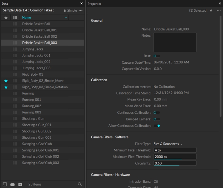
When a Take is selected from the Data pane, related information will be displayed in the Properties pane.
From the Properties pane, you can get the general information about the Take, including the total number of recorded frames, capture data/time, and the list of assets involved in the recording. Also, when needed, the solver settings that were used in the recorded TAK can be modified, and these changes will be applied when performing post-processing reconstruction.
Take name
The camera frame rate in which the take was captured. The Take file will contain the corresponding number of frames for each second.
The frame ID of the first frame saved on the Take.
The frame ID of the last frame saved on the Take.
A timestamp of when the recording was first captured started.
A timestamp of when the recording was ended.
Names of assets that are included in the Take
Comments regarding the take can be noted here for additional information.
Marks the best take. Takes that are marked as best can also be accessed via Motive Batch Processor scripts.
Date and time when the capture was recorded.
The version of Motive which the Take was recorded in. (This applies only to Takes that were captured in versions 1.10 or above)
The build of Motive which the Take was recorded in.
The data quality of the Take which can be flagged by users.
Progress indicator for showing how into the post-processing workflow that this Take has made.
Camera system calibration details for the selected Take. Takes recorded in older versions of Motive may not contain this data.
Shows when the cameras were calibrated.
Shows mean residual offset value during calibration.
Displays percentile distribution of the residual errors.
Displays a mean error value of the detected wand length samples throughout the wanding process.
Displays percentile distribution of the wand errors.
Shows what type of wand was used: Standard, Active, or Micron series.
Displays the length of the calibration wand used for the capture.
Distance from one of the end markers to the center marker, specifically the shorter segment.
The camera filter settings in the Take properties determine which IR lights from the recorded 2D camera data contributes to the post-processing reconstruction pipeline when re-calulating the 3D data when needed.
For more information on these settings in Live mode, please refer to the Application Settings: Live Pipeline page.
The Solver/Reconstruction settings under the Take properties are the 3D data solver parameters that were used to obtain the 3D data saved in the Take file. In Edit mode, you can change these parameters and perform the post-processing reconstruction pipeline to obtain a new set of 3D data with the modified parameters.
For more information on these settings in Live mode, please refer to the Application Settings: Live Pipeline page.
An in-depth look at the properties available for skeleton assets.
This page covers properties specific to skeletons. For general information on using and customizing the Properties pane, see the Properties Pane page. For detailed descriptions of properties for other asset types or devices, please see the following pages:
Skeleton properties determine how Skeleton assets are tracked and displayed in Motive. To view related properties, select a Skeleton asset in the Assets pane or in the 3D viewport, and the corresponding properties will be listed under the Properties pane. These properties can be modified both in Live and Edit mode. Default creation properties are listed under the Application Settings.
Advanced Settings
The Properties pane contains advanced settings that are hidden by default. To access these settings, click the button in the top right corner.
Use the Edit Advanced option to customize which settings are in the Advanced Settings category and which appear in the standard view, to show only the settings that are needed specifically for your capture application.
Select a skeleton asset in the Assets pane or in the 3D viewport, and the corresponding properties will be listed under the Properties pane. These properties can be modified both in Live and Edit mode. Default creation properties are listed under the Assets Settings.
The following items are available in the General Properties section. Properties are Standard unless noted otherwise.
Display the name of selected Skeleton asset in an editable field.
Enable or Disable tracking of the selected Skeleton. A disabled Skeleton will not be tracked, and its data will not be included in the exported or streamed tracking data or displayed in the 3D Viewport.
To hide the markers associated with a disabled asset in the 3D Viewport:
Select Markers -> Hide for Disabled Assets.
The minimum number of markers that must be tracked and labeled in order for a Skeleton, or each Skeleton bone, to be booted or first tracked.
The minimum number of markers that must be tracked and labeled in order for a Skeleton, or each Skeleton bone, to continue to be tracked after the initial boot.
Asset Scale (Advanced Setting)
Increase or decrease the size of the Skeleton by scaling the asset. By default, the Asset Scale is set to 100%.
Deflection Ratio (Advanced Setting)
Allows the asset to deform more or less to accommodate markers that don't fit the model. High values will allow assets to fit onto markers that don't match the model as well.
The following items are available in the Visuals section. Properties are Standard unless noted otherwise.
Set the axis with which the skeleton should be aligned. The default value is Y-Axis.
Default Bone Length (Advanced Setting)
Set the offset (in mm) from the bone to the end effector, along the major axis, for bones that do not have child bones.
Bone Diameter (Advanced Setting)
Set the diameter of the bone (in mm).
Display the Skeleton name in the 3D Perspective View. When selected, a small label will appear over the asset.
Display a label with the status of the Rigid Body's IMU in the 3D Perspective View: IMU Working [Optical] %. If the asset Label is enabled, the IMU state is added after the asset name.
The Optical status indicates whether the Minimum Markers to Continue threshold has been met (Optical), exceed (Good Optical) or is missing. (no optical).
The % status denotes the amount of IMU packets that an IMU Tag is successfully delivering for every 100 frames.
Select how the Skeleton will be shown in the 3D perspective view.
None: Displays only constraints and marker sticks.
Segment: Displays Skeleton as individual Skeleton segments.
Avatar (male): Displays Skeleton as a male avatar.
Avatar (female): Displays Skeleton as a female avatar.
Set the color of the selected Skeleton in the 3D Perspective View. Click the box to bring up the color picker:
Bones
Show or hide Skeleton bones. The bones will display on top of the Visual selection.
This field is available whenever the Bones visual is toggled on and allows you to change the color of the skeleton bones.
Displays orientation axes of each segments in the Skeleton.
Display degrees of freedom, position and orientation, for each bone.
Show the Marker Constraints as transparent spheres on the Skeleton. Marker Constraints are the expected marker locations according to the skeleton solve.
Show lines between labeled Skeleton markers and corresponding expected marker locations. This helps to visualize the offset distance between actual marker locations and the Marker Constraints.
Display a dotted line to connect each Skeleton bone to its respective Marker Constraints.
When enabled, the color of the Skeleton segments will change whenever there are tracking errors.
Red indicates there are no visible markers contributing to the reconstruction in the current frame.
Blue indicates a bone has reached its degree of freedom limit.
Skeleton assets use the Bone Segment geometry, which is selected by default. To use your own geometric model, select Custom Model. This will open the Attached Geometry field.
Attach a valid geometric model to the rigid body to display in the the 3D Viewport. Sphere, box, cylinder, and bone segment shapes are built-in;
The Attached Geometry field becomes available whenever Custom Model is selected for the Rigid Body geometry.
Click the folder to the right of the field to browse to the OBJ or FBX file to replace the Skeleton. Properties configured in the corresponding MTL files alongside the OBJ file will be loaded as well.
Settings to adjust the scale, location, and orientation (Pitch, Yaw, and Roll) are available.
Skeleton templates include pre-defined bones and bone chains that mirror the human body. The Bones properties display data specific to the selected bone. If multiple bones are selected, properties that differ will display Mixed for the value.
To view and update properties for a specific bone, select just that bone in the 3D Viewport.
An editable field that shows the name of the selected bone. When more than one bone is selected, the field will display Mixed.
The hip bone is the root of the skeleton and does not display a Bone Name when selected.
It is not recommended to rename Skeleton bones.
The Parent bone is the first bone in a Bone Chain. This property shows which bone in the Skeleton is the parent of the currently selected bone.
When the selected bone is the hip (or root bone), the Parent field will display None.
When the selected bone is directly attached to the hip (root bone), this field will display the name of the Asset.
When more than one bone is selected and they do not share the same Parent bone, the field will display Mixed.
A Child bone connects to the parent bone in a Bone Chain. This property shows which bone in the Skeleton is the child to the currently selected bone. When the selected bone is the end of the chain, or if there is no bone chain, the Child field will display None.
Identifies the Skeleton bone segment for the selected bone.
Euler angle rotation order used for calculating the bone hierarchy.
Apply double exponential smoothing to translation and rotation of the Skeleton. Increasing this setting may help smooth out noise in the Skeleton tracking, but excessive smoothing can introduce latency. The default value is 0 (disabled).
Compensate for system latency when tracking the corresponding Skeleton by predicting its movement into the future. For this feature to work best, smoothing needs to be applied as well. Please note that using higher values may impact the tracking stability. The default value is 0 (disabled).
When needed, you can damp down translational tracking of a Skeleton bone on the selected axis.
You can also damp down rotational tracking of a Skeleton.
When using Rotation Damping, select whether to apply changes to a selected axis or to all.
An in-depth look at the properties available for Trained Markersets.
Trained Markerset properties determine how the corresponding Trained Markerset asset is tracked and displayed in the 3D Viewport. This page covers the properties specific to Trained Markersets. For general information on using and customizing the Properties pane, see the Properties Pane page. For detailed descriptions of properties for other asset types or devices, please see the following pages:
Select a Trained Markerset asset in the Assets pane or in the 3D viewport, and the corresponding properties will be listed under the Properties pane. These properties can be modified both in Live and Edit mode. Default creation properties are listed under the Assets Settings.
Advanced Settings
Use the Edit Advanced option to customize which settings are in the Advanced Settings category and which appear in the standard view, to show only the settings that are needed specifically for your capture application.
The following items are available in the General Properties section. Properties are Standard unless noted otherwise.
Enter a custom name for the Trained Markerset. The default name is "Markerset." The Asset Name can also be changed by right-clicking the Trained Markerset in the Assets pane.
Enables or Disables tracking of the selected asset. A disabled Trained Markerset will not be tracked, and its data will not be included in the exported or streamed tracking data or displayed in the 3D Viewport.
To hide the markers associated with a disabled asset in the 3D Viewport:
Select Markers -> Hide for Disabled Assets.
An optional text field for storing additional information about the Rigid Body. The data in the Notes field is not included when exporting the asset to a CSV file.
Sets the minimum number of markers that must be tracked and labeled in order for the asset to be booted or first tracked.
Sets the minimum number of markers that must be tracked and labeled in order for the asset to continue to be tracked after the initial boot.
Asset Scale (Advanced Setting)
Increase or decrease the size of the Trained Markerset bone by scaling the asset. By default, the Asset Scale is set to 100%.
Deflection Ratio (Advanced Setting)
Allows the asset to deform more or less to accommodate markers that don't fit the model. High values will allow assets to fit onto markers that don't match the model as well.
The following items are available in the Visuals section. Properties are Standard unless noted otherwise.
Attach a valid geometric model to the Trained Markerset to display in the the 3D Viewport. Sphere, box, cylinder, and bone segment shapes are built-in; to use your own geometric model, select Custom Model. This will open the Attached Geometry field.
The Attached Geometry field becomes available whenever Custom Model is selected for the Rigid Body geometry.
See the section Attaching and Modifying Geometry for information on Geometry settings.
Set the axis with which the bone should be aligned. The coordinate at the end of the bone is expected to be on this axis.
Default Bone Length (Advanced Setting)
Set the offset (in mm) from the bone to the end effector, along the major axis, for bones that do not have child bones.
Bone Diameter (Advanced Setting)
Set the diameter of the bone (in mm).
Display the Trained Markerset name in the 3D Perspective View. When selected, a small label will appear over the asset.
This property is not applicable to Trained Markersets.
Display the marker sticks and bone constraint lines in the 3D Perspective View.
Set the color of the selected Trained Markerset in the 3D Perspective View. Click the box to bring up the color picker:
Bones are optional for Trained Markersets and are added manually when needed. The Bones property toggles on the display of a visual of any bones present in the Markerset in the 3D Viewport.
The shape of the bones indicates whether the asset is solved or unsolved:
Set the color of the bone(s) in the 3D Perspective View.
Display degrees of freedom, position and orientation, for each bone.
Show the Marker Constraints as transparent spheres on the Trained Markerset. Marker Constraints are the expected marker locations according to the Rigid Body solve.
Show lines between labeled Trained Markerset markers and corresponding expected marker locations. This helps to visualize the offset distance between actual marker locations and the Marker Constraints.
Display a dotted line to connect each Marker Constraint to the Trained Markerset bone.
Bones are optional for Trained Markersets and are added manually when needed. Please refer to the Trained Markersets page for instructions on adding bones and creating Bone Chains.
To view and update properties for a specific bone, select just the bone in the 3D Viewport.
An editable field that shows the name of the selected bone. When more than one bone is selected, the field will display Mixed.
This field does not display if the Trained Markerset does not have any bones.
The Parent bone is the first bone in a Bone Chain. This property shows which bone in the Trained Markerset is the parent of the currently selected bone. When the selected bone is the root of the chain, or if there is no bone chain, the Parent field will display the name of the Trained Markerset asset.
When more than one bone is selected, the field will display Mixed.
A Child bone connects to the parent bone in a Bone Chain. This property shows which bone in the Trained Markerset is the child to the currently selected bone. When the selected bone is the end of the chain, or if there is no bone chain, the Child field will display None.
Used for Skeleton and Trained Markerset assets to identify bone segments. The list includes all standard skeleton segments and is not required.
Euler angle rotation order used for calculating the bone hierarchy.
Enter values along one of the axis to reorient the coordinate axis of the selected bone.
Enter values along one of the axis to move the selected bone.
Apply double exponential smoothing to translation and rotation of the Trained Markerset. Increasing this setting may help smooth out noise in the Trained Markerset tracking, but excessive smoothing can introduce latency. The default value is 0 (disabled).
Compensate for system latency when tracking the corresponding Trained Markerset by predicting its movement into the future. Please note that using higher values may impact the tracking stability. The default value is 0 (disabled).
When needed, you can damp down translational tracking of the selected bone on the selected axis.
You can also damp down rotational tracking of the selected bone.
When using Rotation Damping, select whether to apply changes to a selected axis or to all.
Attach a valid geometric model to the Trained Markerset to display in the the 3D Viewport. Sphere, box, cylinder, and bone segment shapes are built-in; to use your own geometric model, select Custom Model. This will open the Attached Geometry field.
The Attached Geometry field becomes available whenever Custom Model is selected for the Rigid Body geometry.
Click the folder to the right of the field to browse to the OBJ or FBX file to replace the Rigid Body. Properties configured in the corresponding MTL files alongside the OBJ file will be loaded as well.
Whenever a geometric model is attached, settings to adjust the scale, location, and orientation (Pitch, Yaw, and Roll) are available.
If you are exporting an OBJ file from Maya, make sure the Ambient Color setting is set to white upon export. If this color is set to black, it will remove textures when the Trained Markerset is deselected.
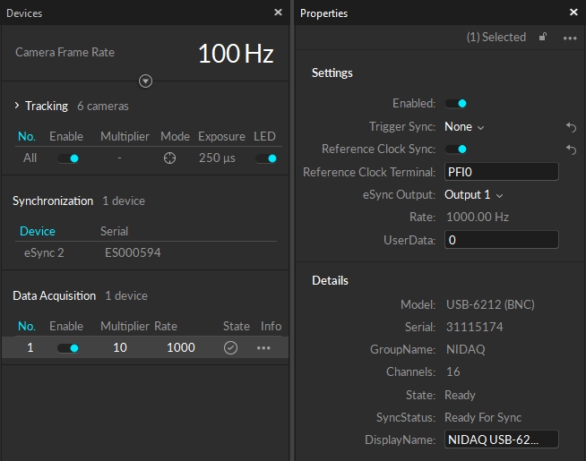
When an NI-DAQ device is selected in Motive, its device information gets listed under the . Just basic information on the used device will be shown in the . For configuring properties of the device, use the .
For more information, read through the NI-DAQ setup page: .
Advanced Settings
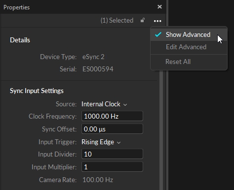
The Properties: NI-DAQ contains advanced settings that are hidden by default. Access these settings by going to the menu on the top-right corner of the pane and clicking Show Advanced and all of the settings, including the advanced settings, will be listed under the pane.
The list of advanced settings can also be customized to show only the settings that are needed specifically for your capture application. To do so, go the pane menu and click Edit Advanced, and uncheck the settings that you wish to be listed in the pane by default. One all desired settings are unchecked, click Done Editing to apply the customized configurations.
Only enabled NI-DAQ devics will be actively measuring analog signals.
This setting determines how the recording of the selected NI-DAQ device will be triggered. This must be set to None for reference clock sync and to Device for recording trigger sync.
None: NI-DAQ recording is triggered when Motive starts capturing data. This is used when using the reference clock signal for synchronization.
Device: NI-DAQ recording is triggered when a recording trigger signal to indicate the record start frame is received through the connected input terminal.
(available only when Trigger Sync is set to Device) Name of the NI-DAQ analog I/O terminal where the recording trigger signal is inputted to.
This setting sets whether an external clock signal is used as the sync reference. For precise synchronization using the internal clock signal sync, set this to true.
True: Setting this to true will configure the selected NI-DAQ device to synchronize with an inputted external sample clock signal. The NI-DAQ must be connected to an external clock output of the eSync on one of its digital input terminals. The acquisition rate will be disabled since the rate is configured to be controlled by the external clock signal.
False: NI-DAQ board will collect samples in 'Free Run' mode at the assigned Acquisition Rate.
(available only when Reference Clock Sync is set to True) Name of the NI-DAQ digital I/O terminal that the external clock (TTL) signal is inputted to.
Set this to the output port of the eSync where it sends out the internal clock signal to the NI-DAQ.
Shows the acquisition rate of the selected NI-DAQ device(s).
Depending on the model, NI-DAQ devices may have different sets of allowable input types and voltage ranges for their analog channels. Refer to your NI-DAQ device User's Guide for detailed information about supported signal types and voltage ranges.
(Default: -10 volts) Configure the terminal's minimum voltage range.
(Default: +10 volts) Configure the terminal's maximum voltage range.
Terminal: RSE Referenced single ended. Measurement with respect to ground (e.g. AI_GND) (Default)
Terminal: NRSE NonReferenced single ended. Measurement with respect to single analog input (e.g. AISENSE)
Terminal: Diff Differential. Measurement between two inputs (e.g. AI0+, AI0-)
Terminal: PseudoDiff Differential. Measurement between two inputs and impeded common ground.
[Advanced] Name of the selected device.
Device model ID, if available.
Device serial number of the selected NI-DAQ assigned by the manufacturer.
Type of device.
Total number of available channels on the selected NI-DAQ device.
_[Advanced]_What mode of Motive playback being used.
Whether the device is ready or not.
Tristate status of either Need Sync, Ready for Sync, or Synced. Updates the "State" icon in the Devices pane.
[Advanced] Internal device number.
User editable name of the device.
An overview of common features available in the Properties Pane.
The Properties pane can be accessed by clicking on the icon on the toolbar.
The Properties pane is used to view and modify properties associated with Takes, assets, and devices that determine how the corresponding items are displayed and tracked. Properties can be modified both in Live and Edit mode. Default creation properties are listed under the .
This page covers features and functions common to the Property pane regardless of what is selected. For a detailed description of each property, please see the following pages:
When a single Take, asset, or device is selected, the Properties pane displays properties specific to the selection. See image at left, below.
Changes made in the Properties pane are applied to all selected objects.
Checked items will appear in the Standard view while unchecked items will only be visible when Show Advanced is selected.
This option removes all customizations made to the properties of the selected asset. Use with caution.
The Properties pane contains advanced settings that are hidden by default. To access these settings, click the button in the top right corner.
Click to open the Visuals menu.
The Properties pane contains advanced settings that are hidden by default. To access these settings, click the button in the top right corner.
Click to open the Visuals menu.
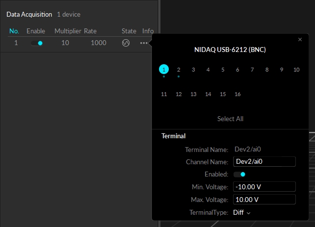
Properties of individual channels can be configured directly from the . As shown in the image, you can click on the icon to bring up the settings and make changes.
Configures the measurement mode of the selected terminal. In general, analog input channels with screw terminals use the single-ended measurement system (RSE), and analog input channels with BNC terminals use the differential (Diff) measurement system. For more information on these terminal types, refer to .
The Properties pane is accessed by clicking the icon on the toolbar. The pane is blank if nothing is selected, or when items that do not have any common properties are selected.
When multiple items are selected, only common properties are displayed; properties that are not shared are not included. Where the selected assets have different values, Motive displays the text Mixed or places the toggle button in the middle position .
Buttons at the top of the Properties pane control what is displayed. Click the button in the top right corner to see all options.
Click the lock icon to lock the display to the currently selected item. The pane will continue to display those properties until the lock is removed, regardless of what is selected in the or the . When unlocked (the default position), the pane updates to reflect the current active selection.
The Properties pane contains advanced settings that are hidden by default. To access these settings, click the button on the top-right corner of the pane and select Show Advanced.
Customize the Standard view to show only the settings that are needed specifically for your capture application. Click the button on the top-right corner of the pane and select Edit Advanced.


