Loading...
Loading...
Loading...
Loading...
Loading...
Loading...
Loading...
Loading...
An introduction to the Applications Settings panel.
Use the Application Settings panel to customize Motive and set default values. This includes camera system setting, data pipeline settings, streaming settings, and hotkeys and shortcuts. Please see the following pages for descriptions of the settings on each tab:
The Settings panel can be opened from the or by clicking the icon on the main toolbar.
Advanced settings are hidden by default. To access, click the button in the top-right corner of the panel and select Show Advanced.
Customize the Standard view to show the settings that you frequently adjust during your capture applications. Click the button on the top-right corner of the pane and select Edit Advanced.
Checked items will appear in the Standard view while unchecked items will only be visible when Show Advanced is selected. Click Done Editing to exit and save your changes when you've made your selections.
To restore all settings to their default values, select Reset Settings from the Edit menu.


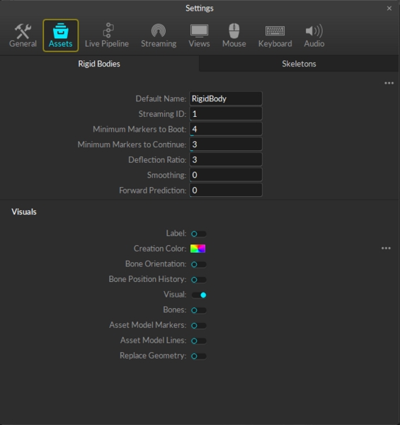
The Assets tab in the application settings panel is where you can configure the creation properties for Rigid Body and Skeleton assets. In other words, all of the settings configured in this tab will be assigned to the Rigid Body and Skeleton that are newly created in Motive.
A list of the default Rigid Body creation properties is listed under the Rigid Bodies tab. These properties are applied to only Rigid Bodies that are newly created after the properties have been modified. For descriptions of the Rigid Body properties, please read through the page.
You can change the naming convention of Rigid Bodies when they are first created. For instance, if it is set to RigidBody, the first Rigid Body will be named RigidBody when first created. Any subsequent Rigid Bodies will be named RigidBody 001, RigidBody 002, and so on.
User definable ID. When streaming tracking data, this ID can be used as a reference to specific Rigid Body assets.
The minimum number of markers that must be labeled in order for the respective asset to be booted.
The minimum number of markers that must be labeled in order for the respective asset to be tracked.
Applies double exponential smoothing to translation and rotation. Disabled at 0.
Compensate for system latency by predicting movement into the future.
Toggle 'On' to enable. Displays asset's name over the corresponding skeleton in the 3D viewport.
Select the default color a Rigid Body will have upon creation. Select 'Rainbow' to cycle through a different color each time a new Rigid Body is created.
When enabled this shows a visual trail behind a Rigid Body's pivot point. You can change the History Length, which will determine how long the trail persists before retracting.
Shows a Rigid Body's visual overlay. This is by default Enabled. If disabled, the Rigid Body will only appear as individual markers with the Rigid Body's color and pivot marker.
When enabled for Rigid Bodies, this will display the Rigid Body's pivot point.
Shows the transparent sphere that represents where an asset first searches for markers, i.e. the Marker Constraints.
When enabled and a valid geometric model is loaded, the model will draw instead of the Rigid Body.
Allows the asset to deform more or less to accommodate markers that don't fix the model. High values will allow assets to fit onto markers that don't match the model as well.
A list of the default Skeleton display properties for newly created Skeletons is listed under the Skeletons tab. These properties are applied to only Skeleton assets that are newly created after the properties have been modified. For descriptions of the Skeleton properties, please read through the page.
Straightens each arm along the line from shoulder to wrist, regardless of the position of the elbow markers.
Straightens each leg along the line from hip to ankle, regardless of the position of the knee markers.
Scales the shin bone length to align the bottom of foot with the floor, regardless of the ankle marker height.
Creates the skeleton with the head upright, removing tilt or bend, regardless of the head marker positions.
Scales the skeleton model so that the top of the head aligns with the top head marker.
Height offset applied to hands to account for markers placed above the write and knuckle joints.
Same as the Rigid Body visuals above:
Label
Creation Color
Bones
Marker Constraints
Changes the color of the skeleton visual to red when there are no markers contributing to a joint.
Display Coordinate axes of each joint.
Displays the lines between labeled skeleton markers and corresponding expected marker locations.
Displays lines between skeleton markers and their joint locations.
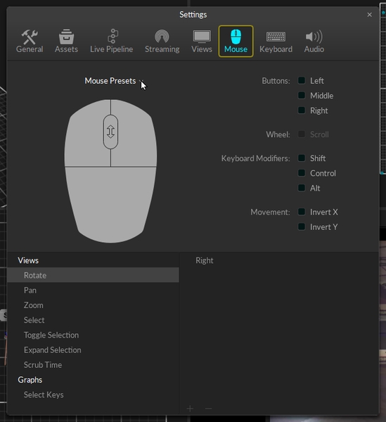
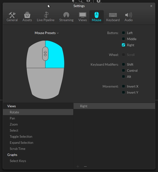
The Mouse tab under the application settings is where you can check and customize the mouse actions to navigate and control in Motive.
The following table shows the most basic mouse actions:
Rotate view
Right + Drag
Pan view
Middle (wheel) click + drag
Zoom in/out
Mouse Wheel
Select in View
Left mouse click
Toggle Selection in View
CTRL + left mouse click
You can also pick a preset mouse action profiles to use. The presets can be accessed from the below drop-down menu. You can choose from the provided presets, or save out your current configuration into a new profile to use it later.
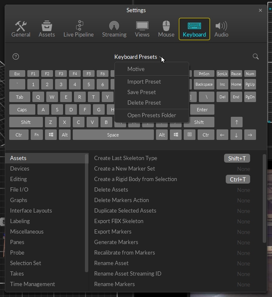
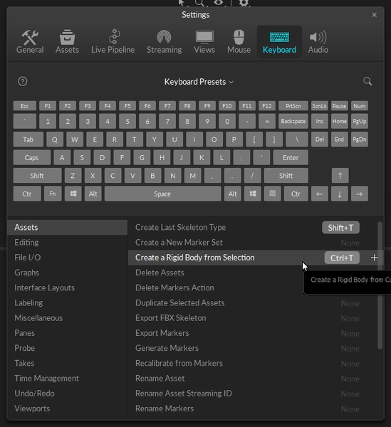
The Keyboard tab under the application settings allows you to assign specific hotkey actions to make Motive easier to use. List of default key actions can be found in the following page also: Motive Hotkeys
Configured hotkeys can be saved into preset profiles to be used on a different computer or to be imported later when needed. Hotkey presets can be imported or loaded from the drop-down menu:
Motive's General Settings defined.
Use the Application Settings panel to customize Motive and set default values. This page will cover the items available on the General tab. Properties are Standard unless noted otherwise.
Please see the following pages for descriptions of the settings on other tabs:
Application Settings can be accessed from the or by clicking the icon on the main toolbar.
The following items are available in the top section of the General section. Settings are Standard unless noted otherwise.
Set the separator (_) and string format specifiers (%03d) for the suffix added after existing file names.
Enable auto-archiving of Takes when .
Set the default device profile, in XML format, to load into Motive. The device profile determines and configures the settings for peripheral devices such as force plates, NI-DAQ, or navigation controllers.
When enabled, all of the session folders loaded in the when exiting will be available again when launching Motive the next time.
Enter the IP address of the glove server, if one is used. Leave blank to use the Local Host IP.
Click the folder icon to the right of the field to select a text file to write the Motive event log to. This allows you to maintain a continuous log that persists between sessions, which can be helpful for troubleshooting.
The following items are available in the Camera Displays section. Settings are Standard unless noted otherwise.
Display the assigned camera number on the front of each camera.
Set how Camera IDs are assigned for each camera in a setup. Available options are:
By Location: Follows the positional order in a clockwise direction, starting from the -X and -Z quadrant with respect to the origin.
By Serial Number: Numbers the cameras in numerical order by serial number.
Custom: Opens the Number property field for editing in the Camera Properties pane.
Set the color of the (Prime Series cameras only) to indicate various camera statuses in Motive.
Live
(Default: Blue) Camera is in Live mode.
(Default: Green) Camera is recording a capture.
(Default: Black) Camera is idle while Motive is in playback mode.
(Default: Yellow) Camera is selected.
(Default: Orange) Camera is in video (reference) mode.
(Default: Enabled) Enable the hibernation light for all cameras when Motive is closed.
(Default: Enabled) Display visuals of wanding coverage in the Camera Viewport during calibration.
(Default: Off) Turn off all numeric LEDs and ring lights on all cameras in the system.
All of the Aim Assist settings are standard settings.
(Default: On) Set the Aim Assist button on the back of the camera to toggle the camera between MJPEG mode and back to the default camera group record mode.
(Default: Grayscale Only) Display aiming crosshairs on the the camera in the Camera Viewport. Options are None, Grayscale Only, All Modes.
(Default: On) Enable the LED light on the Aim Assist button on the back of the Prime Series cameras.
All calibration settings are part of the General tab's Advanced Settings.
(Default: On) Automatically load the previous, or last saved, calibration file when starting Motive.
(Default: 1 s) The duration, in seconds, that the camera system will auto-detect extraneous reflections for masking during process.
(Default: 1,000) Number of samples suggested for calibration. During the process, the camera status in the will turn bright green as cameras reach this target.
(Default: On) Save two TAKE files in the current data folder every time a calibration is performed: one for the calibration wanding and one for the ground plane.
(Default: On) Display visuals of wanding coverage in the Camera Viewport during calibration.
(Default: Off) Allows editing of the camera calibration position with the 3D Gizmo tool.
(Default: Disabled) Select the default mode for Bumped Camera correction. Options are Disabled, Camera Samples, and Selected Camera. Please see the page for more information on these settings and the Bumped Camera tool.
(Default: 100 mm) The maximum distance cameras can be translated by the position correction tool, in mm.
(Default: 120) The maximum length, in seconds, that samples are collected during continuous calibration.
(Default: Off) Allows Continuous Calibration to continue running while recording is in progress.
The Network setting is part of the General tab's Advanced Settings.
(Default: Override) Enable detection of PoE+ switches by High Power cameras (Prime 17W, PrimeX 22, Prime 41, and PrimeX41). LLDP allows the cameras to communicate directly with the switch and determine power availability to increase output to the IR LED rings.
When using Ethernet switches that are not PoE+ enabled or switches that are not LLDP enabled, cameras will not go into high power mode even with this setting on.
All of the Editing settings are standard settings.
(Default: Always Ask) Set Motive's default behavior when changes are made to a TAKE file. Options are:
Do Not Auto-Save: Changes made to TAKE files must be manually saved.
Auto-Save: Updates the TAKE file as changes are made.
Always Ask: Prompts the user to save TAKE files upon exit.
In Motive, the Application Settings can be accessed under the View tab or by clicking icon on the main toolbar. Default Application Settings can be recovered by Reset Application Settings under the Edit Tools tab from the main Toolbar.
If you have an audio input device, you can record synchronized audio along with motion capture data in Motive. Recorded audio files can be played back from a captured Take or be exported into a WAV audio files. This page details how to record and playback audio in Motive. Before using an audio input device (microphone) in Motive, first make sure that the device is properly connected and configured in Windows.
In Motive, audio recording and playback settings can be accessed from .
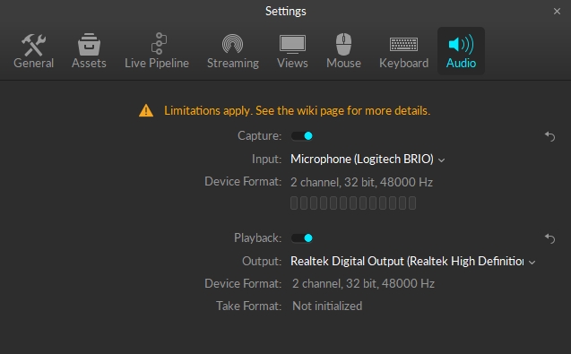
In Motive, open the Audio Settings, and check the box next to Enable Capture.
Select the audio input device that you want to use.
Press the Test button to confirm that the input device is properly working.
Make sure the device format of the recording device matches the device format that will be used in the playback devices (speakers and headsets).
Enable the Audio device before loading the TAK file with audio recordings. Enabling after is currently not supported, as the audio engine gets initialized on TAK load
Open a Take that includes audio recordings.
To playback recorded audio from a Take, check the box next to Enable Playback.
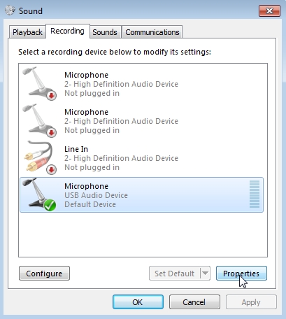
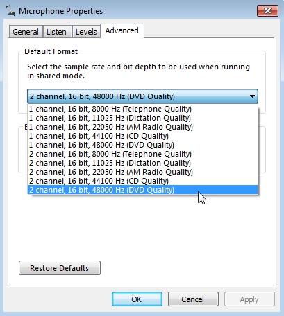
In order to playback audio recordings in Motive, audio format of recorded sounds MUST match closely with the audio format used in the output device. Specifically, communication channels and frequency of the audio must match. Otherwise, recorded sound will not be played back.
The recorded audio format is determined by the format of a recording device that was used when capturing Takes. However, audio formats in the input and output devices may not always agree. In this case, you will need to adjust the input device properties to match them. Device's audio format can be configured under the Sound settings in Windows. In Sound settings (accessed from Control Panel), select the recording device, click on Properties, and the default format can be changed under the Advanced Tab, as shown in the image below.
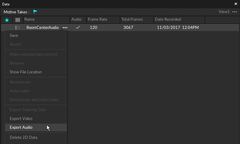
Recorded audio files can be exported into WAV format. To export, right-click on a Take from the and select Export Audio option in the context menu.
If you want to use an external audio input system to record synchronized audio, you will need to connect the motion capture system into a Genlock signal or a Timecode device. This will allow you to precisely synchronize the recorded audio along with the capture data.
For more information on synchronizing external devices, read through the page.
Capture the Take.
Make sure the configurations in Device Format closely match the Take Format. This is elaborated further in the section below.
Play the Take.


In Motive, the Application Settings can be accessed under the View tab or by clicking icon on the main toolbar. Default Application Settings can be recovered by Reset Application Settings under the Edit Tools tab from the main Toolbar.
In Motive, the Data Streaming pane can be accessed under the View tab or by clicking icon on the main toolbar. For explanations on the streaming workflow, read through the Data Streaming page.
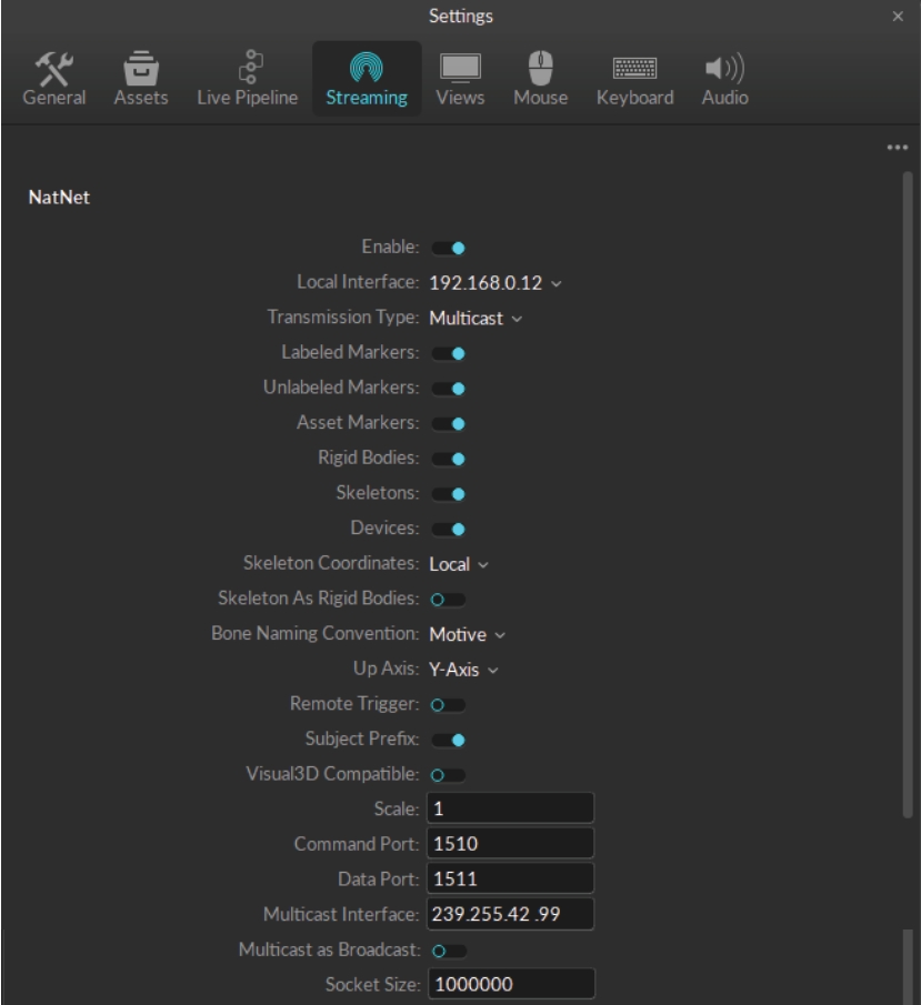
This section allows you to stream tracking data via Motive's free streaming plugins or any custom-built NatNet interfaces. To begin streaming, select Broadcast Frame Data. Select which types of data (e.g. markers, Rigid Bodies, or Skeletons) will be streamed, noting that some third party applications will only accept one type of data. Before you begin streaming, ensure that the network type and interface are consistent with the network you will be streaming over and the settings in the client application.
(Default: False) Enables/disables broadcasting, or live-streaming, of the frame data. This must be set to true in order to start the streaming.
(Default: loopback) Sets the network address which the captured frame data is streamed to. When set to local loopback (127.0.0.1) address, the data is streamed locally within the computer. When set to a specific network IP address under the dropdown menu, the data is streamed over the network and other computers that are on the same network can receive the data.
(Default: Multicast) Selects the mode of broadcast for NatNet. Valid options are: Multicast, Unicast.
(Default: True) Enables, or disables, streaming of labeled Marker data. These markers are point cloud solved markers.
(Default: True) Enables/disables streaming of all of the unlabeled Marker data in the frame.
(Default: True) Enables/disables streaming of the Marker Set markers, which are named collections of all of the labeled markers and their positions (X, Y, Z). In other words, this includes markers that are associated with any of the assets (Marker Set, Rigid Body, Skeleton). The streamed list also contains a special marker set named all which is a list of labeled markers in all of the assets in a_Take_. In this data, Skeleton and Rigid Body markers are point cloud solved and model-filled on occluded frames.
(Default: True) Enables/disables streaming of Rigid Body data, which includes the name of Rigid Body assets as well as positions and orientations of their .
(Default: Skeletons) Enables/disables streaming of Skeleton tracking data from active Skeleton assets. This includes the total number of bones and their positions and orientations in respect to global, or local, coordinate system.
When enabled, this streams active peripheral devices (ie. force plates, Delsys Trigno EMG devices, etc.)
(Default: Global) When set to Global, the tracking data will be represented according to the global coordinate system. When this is set to Local, the streamed tracking data (position and rotation) of each skeletal bone will be relative to its parent bones.
(Default: Motive) Sets the bone naming convention of the streamed data. Available conventions include Motive, FBX, and BVH. The naming convention must match the format used in the streaming destination.
(Default: Y Axis) Selects the upward axis of the right-hand coordinate system in the streamed data. When streaming onto an external platform with a Z-up right-handed coordinate system (e.g. biomechanics applications) change this to Z Up.
(Default: False) Allows using the remote trigger for recording using XML commands. See more:
(Default: False) When set to true, Skeleton assets are streamed as a series of Rigid Bodies that represent respective Skeleton segments.
(Default: True) When set to true, associated asset name is added as a subject prefix to each marker label in the streamed data.
Enables streaming to Visual3D. Normal streaming configurations may be not compatible with Visual3D, and this feature must be enabled for streaming tracking data to Visual3D.
Applies scaling to all of the streamed position data.
(Default: 1510) Specifies the port to be used for negotiating the connection between the NatNet server and client.
(Default: 1511) Specifies the port to be used for streaming data from the NatNet server to the client(s).
Specifies the multicast broadcast address. (Default: 239.255.42.99). Note: When streaming to clients based on NatNet 2.0 or below, the default multicast address should be changed to 224.0.0.1 and the data port should be changed to 1001.
Warning: This mode is for testing purposes only and it can overflood the network with the streamed data.
When enabled, Motive streams out the mocap data via broadcasting instead of sending to Unicast or Multicast IP addresses. This should be used only when the use of Multicast or Unicast is not applicable. This will basically spam the network that Motive is streaming to with streamed mocap data which may interfere with other data on the network, so a dedicated NatNet streaming network may need to be set up between the server and the client(s).To use the broadcast set the streaming option to Multicast and have this setting enabled on the server. Once it starts streaming, set the NatNet client to connect as Multicast, and then set the multicast address to 255.255.255.255. Once Motive starts broadcasting the data, the client will receive broadcast packets from the server.
Warning: Do not modify unless instructed.
(Default: 1000000)
This controls the socket size while streaming via Unicast. This property can be used to make extremely large data rates work properly.
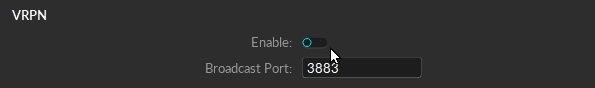
For information on streaming data via the VRPN Streaming Engine, please visit the . Note that only 6 DOF Rigid Body data can be streamed via VRPN.
(Default: False) When enabled, Motive streams Rigid Body data via the VRPN protocol.
[Advanced] (Default: 3883) Specifies the broadcast port for VRPN streaming. (Default: 3883).
Motive's Views Settings defined.
Use the Application Settings panel to customize Motive and set default values. This page will cover the items available on the View tab. Properties are Standard unless noted otherwise.
Please see the following pages for descriptions of the settings on other tabs:
Application Settings can be accessed from the or by clicking the icon on the main toolbar.
The 2D tab of the Views settings contains display settings for the in Motive. These are all standard settings.
(Default: Black) Set the background color of the .
(Default: On) Display yellow crosshairs in the 2D camera view based on the calculated position of the markers selected in the 3D Perspective View.
Crosshairs that are not directly over the marker may indicate occlusion or poor camera calibration.
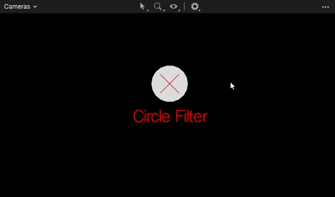
(Default: On) When enabled, the Cameras View displays a red graphic over markers filtered out by the camera's circularity and size filters. This is useful for determining why certain cameras are not tracking specific markers in the view.
The 3D tab contains display settings for the in Motive. Settings are Standard unless noted otherwise.
This section contains settings that control the look of the 3D Perspective View. All are standard settings.
(Default: black) Set the background color of the Perspective View.
(Default: off) Turn on a gradient “fog” effect.
(Default: white) Set the color of the ground plane grid.
(Default: 6 meters) Set the width, in meters, of the ground plane grid.
(Default: 6 meters) Set the length, in meters, of the ground plane grid.
(Default: off) Display the floor plane in the Perspective View. When disabled, only the floor grid is visible.
(Default: gray) Set the color for the floor plane. This option is only available when the Floor Plane setting is enabled.
(Default: yellow) Set the color of selected objects in the 3D Viewport. This color is applied to secondary items when multiple items are selected.
(Default: cyan) Set the color of the primary selected object in the 3D Viewport. When multiple objects are selected, the primary selection is the object that was selected last.
Settings in this section determine which informational overlays to include in the 3D Viewport. All settings are standard unless noted otherwise.
(Default: on) Display the coordinate axis in the lower left corner. This overlay can also be toggled on or off from the Visuals menu in the 3D Viewport.
When using an external timecode signal through an eSync device, this setting determines where to display the timecode:
Show in 3D View: Display the timecode at the bottom of the 3D Viewport. This is the default setting.
Show in Control Deck: Display the timecode in the control deck below the 3D Viewport.
Do not Show: Hide the timecode.
Determine where to display the timecode for Precision Time Protocol (PTP) devices, if in use:
Show in 3D View: Display the PTP timecode at the bottom of the 3D Viewport.
Show in Control Deck: Display the PTP timecode in the control deck below the 3D Viewport.
Do not Show: Hide the PTP timecode. This is the default setting.
(Default: on) Show marker count details in the bottom-right corner:
Total markers tracked
Total markers selected
This overlay can also be toggled on or off from the Visuals menu in the 3D Viewport.
(Default: off) Display the OptiTrack logo in the top right corner.
(Default: off) Display the refresh rate in the top left corner.
Settings in this section determine how markers are displayed in the 3D Viewport. All settings are standard unless noted otherwise.
(Default: custom) Determine whether markers are represented by the calculated size or overwritten with a set diameter (custom).
(Default: 14mm) Determines the fixed diameter of all 3D markers when the marker Size is set to Custom.
(Default: white) Set the color for labeled markers. Markers labeled using either a Rigid Body or Skeleton solve are colored according to their asset properties.
(Default: white) Set the color for passive markers. Retro-reflective markers or continuously illuminating IR LEDs are recognized as passive markers in Motive.
(Default: cyan) Set the color for .
(Default: white) Set the color for active markers that have yet to be identified in Motive. The marker color will change to the Active color once the marker is identified.
(Default: white) Set the color for measurement points created using the .
(Default: 70) Set the opacity level for markers in a solved asset. Lower values reduce the brightness and color of the markers in the 3D Viewport.
Determine whether marker labels displayed in the 3D Viewport will include the Asset name (the default setting) or just the marker label name.
(Default: off) Display the 3D positions and estimated diameter of selected markers. If the marker label visual is also enabled, the marker info will display at the end of the label.
(Default: on) Display a trail to show the history of marker positions over time. When the marker is selected, the trail will use the color chosen in the Selection Color setting (yellow by default). The trail for unselected markers will follow the color of the marker itself.
(Default: on) When marker history is selected, this setting restricts the marker history trails to only the markers selected in the 3D Viewport.
(Default: 250) Set the number of past frames to include in the marker history.
(Default: 50) Set the opacity level for marker sticks when their markers are not being tracked. Lower values reduce the brightness and color of the sticks in the 3D Viewport.
Settings in this section determine how cameras are displayed in the 3D Viewport. All settings are standard.
(Default: teal) Set the color of tracking cameras in the 3D Perspective View. Tracking cameras are set to .
(Default: magenta) Set the color of reference cameras in the 3D Perspective View. Reference cameras are set to capture MJPEG grayscale videos or color videos (Prime Color series).
(Default: off) Use color to distinguish cameras by partitions rather than function.
Cameras detect reflected rays of infrared light to track objects in the capture volume. Settings in this section determine how camera rays are displayed in the 3D Viewport. All settings are standard unless noted otherwise.
(Default: green) Set the color for Tracked Rays, which are rays that connect a camera to a marker.
(Default: green) Set the color for rays that are tracked but connect to unlabeled markers.
(Default: red) Set the color for untracked rays, which are rays that do not connect to a marker.
(Default: off) Display all tracked rays. Additional options to display tracked rays are available from the Menu in the 3D Viewport. Click the button and select Tracked Rays to see more.
The 3D Viewport Visual Aids includes an option to view the Capture Volume. Settings in this section determine how the Capture Volume visual displays. All settings are standard.
(Default: checkered blue) Set the color used to visualize the capture volume.
(Default: 3) Set the minimum number of cameras required to form a field of view (FOV) overlap when visualizing the parameters of the capture volume.
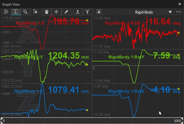
The Graphs tab under the Views settings contains display settings for the . These are all standard settings.
(Default: dark) Set the color to use for the plot guidelines.
(Default: black) Set the background color to use for the plots.
(Default: on) When enabled, the y-axis of each plot will autoscale to fit all the data in the view, and zoom automatically for best visualization. For fixed y-plot ranges, this setting can be disabled. See the page for more information.
(Default: none) Preferred used for Live mode. Enter the name of the layout you wish to use exactly as it appears on the layout menu. Both System layouts and User layouts can be used.
(Default: none) Preferred used for Edit mode. Enter the name of the layout you wish to use exactly as it appears on the layout menu. Both System layouts and User layouts can be used.
(Default: 1000) The scope, in frames, of the domain range used for plotting graphs.


Motive's Live Pipeline Settings defined.
Use the Application Settings panel to customize Motive and set default values. This page will cover the items available on the Live Pipeline tab. Properties are Standard unless noted otherwise.
Live Pipeline settings contain camera filter and solver settings for obtaining 3D data in Motive. These settings are optimized by default to provide high-quality tracking for most applications.
Please see the following pages for descriptions of the settings on other tabs:
Application Settings can be accessed from the or by clicking the icon on the main toolbar.
Solver settings control how each marker's trajectory is reconstructed into the 3D space and how Rigid Bodies, Skeletons, and Trained Markersets track. The solver is designed to work for most applications using the default settings. However, in some instances, changing settings will lead to better tracking results.
The standard settings are those most likely to be customized by the user. We recommend exercising caution before making adjustments to any Solver advanced settings.
These properties are only available when Advanced settings are displayed.
The Trajectorizer settings control how the 2D marker data is converted into 3D points in the calibrated volume. The Trajectorizer performs reconstruction of 2D data into 3D data, and these settings control how markers are created in the 3D scene over time.
The Booter settings control when the assets start tracking, or boot, on the trajectorized 3D markers in the scene, which determine when Rigid Bodies and/or Skeletons track on a set of markers.
This Cameras tab of the Live Pipeline settings is used to configure the filter properties for all the cameras in the system.
The Camera Filters - Hardware section is shown only when the advanced settings are displayed.
Save Preset: Saves the current configuration as a new .MOTIVE file. If the file is saved in the Presets folder, it will appear in the top section of the drop down list.
Delete Preset: Removes obsolete presets from the list and deletes the .MOTIVE file.
Open Presets Folder: Opens the Presets folder in an Explorer window for direct file management. Use this option if you wish to move files in bulk or to save old presets in an alternate location.
Ellipsoid
Save Preset: Saves the current configuration as a new .MOTIVE file. If the file is saved in the Presets folder, it will appear in the top section of the drop down list.
Delete Preset: Removes obsolete presets from the list and deletes the .MOTIVE file.
Open Presets Folder: Opens the Presets folder in an Explorer window for direct file management. Use this option if you wish to move files in bulk or to save old presets in an alternate location.


