A USB camera system provides high-quality motion capture for small to medium size volumes at an affordable price range. USB camera models include the Flex series (Flex 3 and Flex 13) and Slim 3U models. USB cameras are powered by the OptiHub, which is designed to maximize the capacity of Flex series cameras by providing sufficient power to each camera, allowing tracking at long ranges.
For each USB system, up to four OptiHubs can be used. When incorporating multiple OptiHubs in the system, use RCA synchronization cables to interconnect each hub. A USB system is not suitable for a large volume setup because the USB 2.0 cables used to wire the cameras have a 5-meter length limitation.
If needed, up to two active USB extensions can be used when connecting the OptiHub to the host PC. However, the extensions should not be used between the OptiHub and the cameras. We do not support using more than 2 USB extensions anywhere on a USB 2.0 system running Motive.
Main Components
Host PC
USB Cameras
OptiHub(s) and a power supply for each hub.
USB 2.0 cables:
USB 2.0 Type A/B per OptiHub.
USB 2.0 Type B/mini-b per camera.
OptiHub
The OptiHub is a custom-engineered USB hub that is designed to be incorporated in a USB camera system. It provides both power and external synchronization options. Standard USB ports do not provide enough power for the IR illumination within Flex 13 cameras and they need to be routed through an OptiHub in order to activate the LED array.
USB Load Balancing
When connecting hubs to the computer, load balancing becomes important. Most computers have several USB ports on the front and back, all of which go through two USB controllers. Especially for a large camera count systems (18+ cameras), it is recommended that you evenly split the cameras between the USB controllers to make the best use of the available bandwidth.
OptiSync
OptiSync is a custom synchronization protocol which sends the synchronization signals through the USB cable. It allows each camera to have one USB cable for both data transfer and synchronization instead of having separate USB and daisy-chained RCA synchronization cables as in the older models.
Difference Between OptiSync and Wired Sync
OptiSync
The OptiSync is a custom camera-to-camera synchronization protocol designed for Flex series cameras. The OptiSync protocol sends and receives sync signals over the USB cable, without the need for RCA sync cables. This sync method is only available when using Flex 3 or Flex 13 cameras connected to the OptiHub.
Wired Sync
The Wired Sync is a camera-to-camera synchronization protocol using RCA cables in a daisy chain arrangement. With a master RCA sync cable connecting the master camera to the OptiHub, each camera in the system is connected in series via RCA sync cables and splitters. The V100:R1 (Legacy) and the Slim 3U cameras utilize Wired Sync only, and therefore any OptiTrack system containing these cameras need to be synchronized through the Wired Sync. Wired Sync is optionally available for Flex 3 cameras.
At this point, all of the connected cameras will be listed on the Devices pane and the 3D viewport when you start up Motive. Check to make sure all of the connected cameras are properly listed in Motive.
Then, open up the Status Log panel and check there are no 2D frame drops. You may see a few frame drops when booting up the system or when switching between Live and Edit modes; however, this should only occur just momentarily. If the system continues to drop 2D frames, it indicates there is a problem with how the system is delivering the camera data. Please refer to the troubleshooting section for more details.
The OptiTrack Duo/Trio tracking bars are factory calibrated and there is no need to calibrate the cameras to use the system. By default, the tracking volume is set at the center origin of the cameras and the axis are oriented so that Z-axis is forward, Y-axis is up, X-axis is left.
If you wish to change the location and orientation of the global axis, you can use the Coordinate Systems Tool which can be found under the Tools tab.
Adjusting the Coordinate System Steps
Place the calibration square at the desired origin.
[Motive] Open the Coordinate System Tools pane under the Tools tab.
[Motive] Click the Set Ground Plane button from the Coordinate System Tools pane, and the global origin will be adjusted.
When using the Duo/Trio tracking bars, you can set the coordinate origin at a desired location and orientation using a . Make sure the calibration square is oriented properly.
[Motive] Select the Calibration square markers from the
The API reports "world-space" values for markers and rigid body objects at each frame. It is often desirable to convert the coordinates of points reported by the API from the world-space (or global) coordinates into the local space of the rigid body. This is useful, for example, if you have a rigid body that defines the world space that you want to track markers within.
Rotation values are reported as both quaternions, and as roll, pitch, and yaw angles (in degrees). Quaternions are a four-dimensional rotation representation that provide greater mathematical robustness by avoiding "gimbal" points that may be encountered when using roll, pitch, and yaw (also known as Euler angles). However, quaternions are also more mathematically complex and are more difficult to visualize, which is why many still prefer to use Euler angles.
There are many potential combinations of Euler angles so it is important to understand the order in which rotations are applied, the handedness of the coordinate system, and the axis (positive or negative) that each rotation is applied about.
These are the conventions used in the API for Euler angles:
Rotation order: XYZ
All coordinates are *right-handed*
To create a transform matrix that converts from world coordinates into the local coordinate system of your chosen rigid body, you will first want to compose the local-to-world transform matrix of the rigid body, then invert it to create a world-to-local transform matrix.
To compose the rigid body local-to-world transform matrix from values reported by the API, you can first compose a rotation matrix from the quaternion rotation value or from the yaw, pitch, and roll angles, then inject the rigid body translation values. Transform matrices can be defined as either "column-major" or "row-major". In a column-major transform matrix, the translation values appear in the right-most column of the 4x4 transform matrix. For purposes of this article, column-major transform matrices will be used. It is beyond the scope of this article, but it is just as feasible to use row-major matrices by transposing matrices.
In general, given a world transform matrix of the form: M = [ [ ] Tx ] [ [ R ] Ty ] [ [ ] Tz ] [ 0 0 0 1 ]
where Tx, Tz, Tz are the world-space position of the origin (of the rigid body, as reported from the API), and R is a 3x3 rotation matrix composed as: R = [ Rx (Pitch) ] * [ Ry (Yaw) ] * [ Rz (Roll) ]
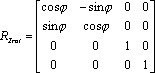
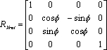
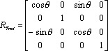
where Rx, Ry, and Rz are 3x3 rotation matrices composed according to:
A handy trick to know about local-to-world transform matrices is that once the matrix is composed, it can be validated by examining each column in the matrix. The first three rows of Column 1 are the (normalized) XYZ direction vector of the world-space X axis, column 2 holds the Y axis, and column 3 is the Z axis. Column 4, as noted previously, is the location of the world-space origin. To convert a point from world coordinates (coordinates reported by the API for a 3D point anywhere in space), you need a matrix that converts from world space to local space. We have a local-to-world matrix (where the local coordinates are defined as the coordinate system of the rigid body used to compose the transform matrix), so inverting that matrix will yield a world-to-local transformation matrix. Inversion of a general 4x4 matrix can be slightly complex and may result in singularities, however we are dealing with a special transform matrix that only contains rotations and a translation. Because of that, we can take advantage of the method shown here to easily invert the matrix:
http://stackoverflow.com/questions/2624422/efficient-4x4-matrix-inverse-affine-transform
Once the world matrix is converted, multiplying it by the coordinates of a world-space point will yield a point in the local space of the rigid body. Any number of points can be multiplied by this inverted matrix to transform them from world (API) coordinates to local (rigid body) coordinates.
The API includes a sample (markers.sln/markers.cpp) that demonstrates this exact usage.
0 to 50 degrees Celsius
20% to 80% relative humidity (non-condensing)
Download the Motive 3.1 software installer from the Motive Download Page to each host PC.
Run the installer and follow its prompts.
Each V120:Duo and V120:Trio includes a free license to Motive:Tracker for one device. No software license activation or security key is required.
To use multiple V120 devices, connect each one to a separate host PC with Motive installed.
Please see the Host PC Requirements section of the Installation and Activation page for computer specifications.
V120 Duo or Trio device
I/O-X (breakout box)
Power adapter and cord
Camera bar cable (attached to I/O-X)
USB Uplink cable
Mount the camera bar in the designated location.
Connect the Camera Bar Cable to the back of the camera and to the I/O-X device, as shown in the diagram above.
Connect the I/O-X device to the PC using the USB uplink cable.
Connect the power cable to the I/O-X device and plug it into a power source.
Make sure the power is disconnected from the I/O-X (breakout box) before plugging or unplugging the Camera Bar Cable. Hot-plugging this cable may damage the device.
The V120 cameras use a preset frequency for timing and can run at 25 Hz, 50 Hz or 100 Hz. To synchronize other devices with the Duo or Trio, use a BNC cable to connect an input port on the receiving device to the Sync Out port on the I/O-X device.
Output options are set in the Properties pane. Select T-Bar Sync in the Devices pane to change output options:
Exposure Time: Sends a high signal based on when the camera exposes.
Passthrough: Sync In signal is passed through to the output port.
Recording Gate: Low electrical signal (0V) when not recording and a high (3.3V) signal when recording is in progress.
Gated Exposure Time: ends a high signal based on when the camera exposes, only while recording is in progress.
Timing signals from other devices can be attached to the V120 using the I/O-X device's Sync In port and a BNC cable. However, this port does not allow you to change the rate of the device reliably. The only functionality that may work is passing the data through to the output port.
The Sync In port cannot be used to change the camera's frequency reliably.
The V120 ships with a free license for Motive:Tracker installed.
The camera is pre-calibrated and no wanding is required. The user can set the ground plane.
The V120 runs in Precision, Grayscale, and MJPEG modes. Object mode is not available.
LED lights on the back of the V120 indicate the device's status.
None
Device is off.
Red
Device is on.
Amber
Device is recognized by Motive.
None
Tracking/video is not enabled.
Solid Red
Configured for External-Sync: Sync Not Detected
Flashing Red
Configured for Default, Free Run Mode,
or External-Sync: Sync Detected
Solid Green
Configured for Internal-Sync: Sync Missing
Flashing Green
Configured for Internal-Sync: Sync Present