Loading...
Loading...
Loading...
Loading...
Loading...
Loading...
Loading...
Loading...
Loading...
Loading...
This page provides instructions on how to set up the OptiTrack Streaming Client Unreal Engine plugin. This plugin is intended for Virtual Reality customers, but can be used with many other applications.
Next step is to configure the client. Follow below instructions to install and configure the OptiTrack Unreal Engine plugin to receive the streamed tracking data.
OptiTrack - Streaming Client Plugin (required)
Download the Unreal Plugin.
Extract the contents from the ZIP file.
Open the extracted OptiTrack folder, transfer the entire "OptiTrack" folder into the Unreal Engine's plugin directory located in the C:\Program Files\Epic Games\5.#\Engine\Plugins folder (there will be other plugins in that folder already).
Open/Create a new Unreal Engine project.
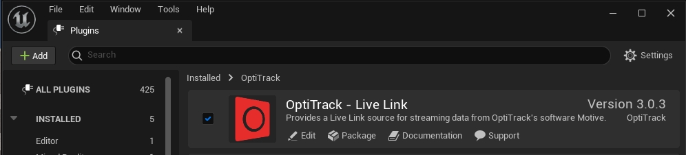
Under the Edit menu, click Plugins to open up the panel where all of the available plugins are listed.
Browse to OptiTrack section and enable the "OptiTrack - Streaming Client".
Click Apply to submit the changes. It will require the Unreal Engine project to be restarted
Once the OptiTrack - Streaming Client plugin is enabled, the OptiTrack Client Origin actor will be available in Unreal Engine.
OptiTrack Client Origin
The OptiTrack Client Origin class enables the Unreal Engine (client) to communicate with the Rigid Body, Skeleton, and HMD tracking data streamed from Motive.
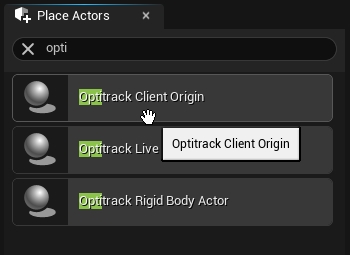
To add the client origin, simply drag-and-drop the OptiTrack Client Origin from the Place Actors panel into the level. Once the client origin is placed within the level, its position and orientation will reconcile the global origin of Motive in Unreal Engine. In other words, the tracking data will be represented relative to where this Client Origin object is positioned and oriented.
Global Origin: Both position and orientation of the OptiTrackClientOrigin will represent the global origin of the tracking volume within Motive.
[Motive] Make sure that NatNet streaming is enabled in the Streaming Pane in Motive.
[Unreal] Once the plugin is added and enabled in the project, the OptiTrack Client Origin class will be available from the Place Actors panel.
[Unreal] Drag and drop the OptiTrack Client Origin into the scene.
[Unreal] Place the OptiTrack Client Origin at the desired location within the scene.
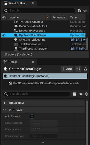
[Unreal] Select the instantiated OptiTrackClientOrigin object from the World Outliner panel.
[Unreal] In the Details panel, make sure its Auto Connect setting is checked. This configures the client origin to automatically search the network and connect to Motive.
Now that the client origin is set, the client origin will attempt to connect to Motive and start receiving the tracking data whenever the scene is played.
Connecting to a designated IP address
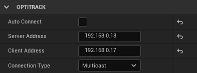
If you wish to connect to a server on a specific network address, you can uncheck the Auto Connect setting and manually enter the Server IP Address chosen in the Streaming Pane in Motive, Client IP Address, and Connection Type associated with Motive. You may need to run the ipconfig command in the command prompt to obtain an appropriate IP address of the client.
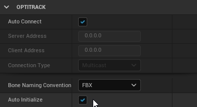
Advance settings: Auto-initialize
By default, the auto-initialize feature is enabled and the client origin will get auto-initialized whenever the scene is played. But when needed, you can disable this and set up the project so the client origin gets initialized when a user-defined event is triggered.
Actor objects in Unreal Engine can be animated using Rigid Body tracking data from Motive. Once the OptiTrack - Streaming Client plugin is enabled in the project, OptiTrack Rigid Body component will be available to use. By attaching this component onto an actor, you can animate its child actors according to the movement of a Rigid Body in Motive. Each Rigid Body component is given a Tracking ID value which associates with the Streaming ID of a Rigid Body in Motive. Once associated, the data from the corresponding Rigid Body will be used to update the transform of the target actor in Unreal Engine.
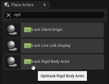
[Unreal] From the Place Actors panel, search for OptiTrack Rigid Body Actor, then drag-and-drop the actor into the scene.
[Unreal] With this Rigid Body actor selected, attach the target actor that you wish to animate using the Details panel. Make sure the target actor's transformation is set to movable.
[Unreal] Set the relative locations and rotations to all zeroes on this target actor. This actor should be listed as a child of the Rigid Body actor.
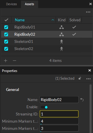
[Motive] In Motive, assign a value to Streaming ID property for the target Rigid Body.
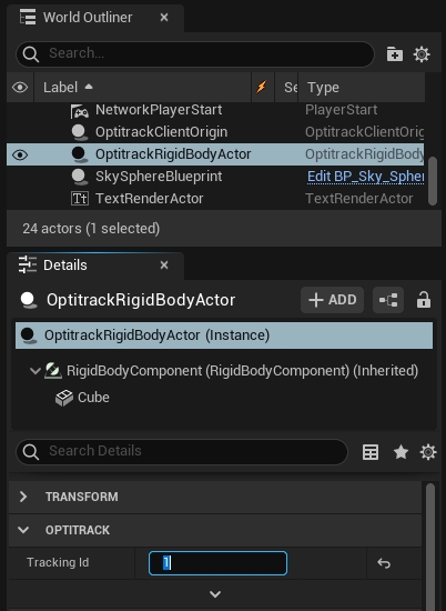
[Unreal] In the properties of the OptiTrack Rigid Body Actor component, match the Tracking ID with the Streaming ID of the Rigid Body asset in Motive.
Make sure both Motive and OptiTrack Client Origin is set up for streaming, hit Play, and the attached actor object will be animated according to the live-streamed Rigid Body tracking data.
ID of the Rigid Body used to derive the position and orientatation transform of the attached actor. This ID must match with the Streaming ID of the respective Rigid Body in Motive.
When this is checked, the corresponding Rigid Body actor will be hidden from the level until the associated Rigid Body data is streamed out from Motive and received by the plugin.
Low latency update feature allows Rigid Body position and orientation transform to be updated immediately before rendering minimizing the latency. This is enabled by default. For debugging, you can check this setting to disable this behavior.
This sets a specific client origin to use for receiving tracking data. When this is unset, the plugin will default to the first client origin that it finds in the scene.
When this is set to true, the Rigid Body transform data from Motive will be applied in respect to the parent actor's pivot coordinates. By default, this is set to false, and all of the tracking data will be applied in respect to the pivot axis of the client origin.
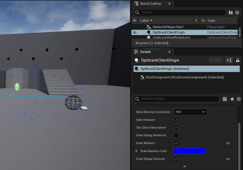
When needed, you can also draw labeled marker data from Motive into the scene in UE. In most applications, you do not have to draw the markers as Rigid Body data and the Skeleton data will be used instead; however, getting markers generated in the scene may be helpful for debugging purposes. To enable drawing of the markers:
[UE4] Expand the OptiTrackClientOrigin (Instance) properties, and enable the Draw Markers checkbox.
[Motive] Labeled Markers setting in the data streaming pane must be enabled.
Skeleton streaming is supported only in plugin versions 1.9 or above.
Follow the below steps to set up Skeleton streaming onto Unreal Engine.
1. Create a Animation Blueprint in the 3D View
Step 1. Navigate to a character folder. With Paragon sample characters, it is located in Characters → Heros → [Character Name] → Meshes.
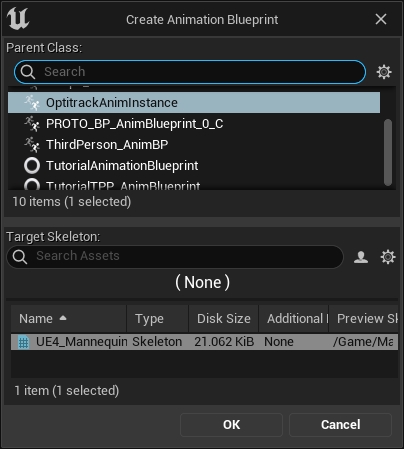
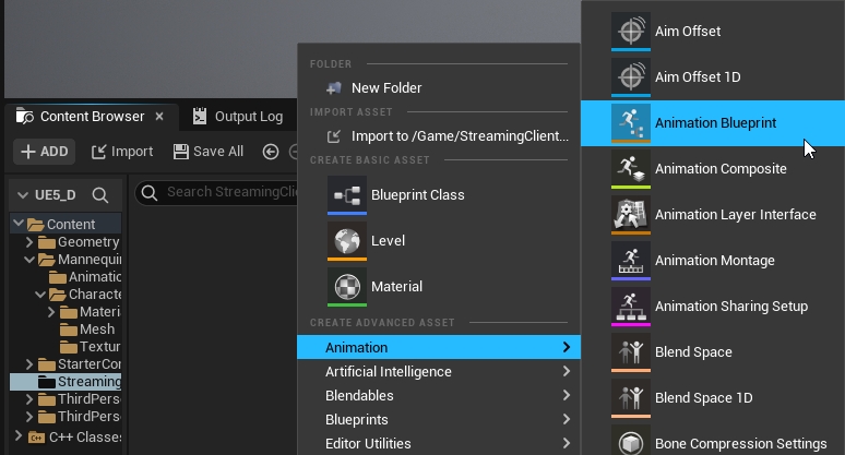
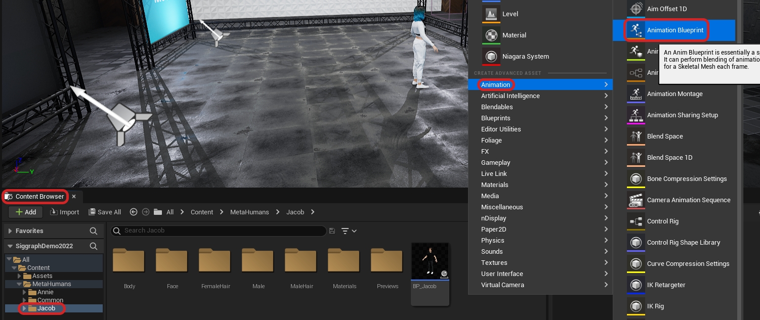
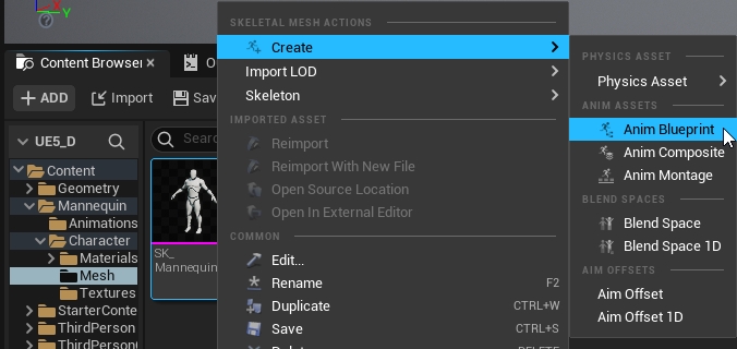
Step 2. Right-click the blank space in the Content Browser pane, then select Animation → Animation Blueprint.
Step 3. On the pop-up window, select the OptiTrackAnimInstance at the parent class section at the top and click on the target Skeleton name at the bottom. Then click OK.
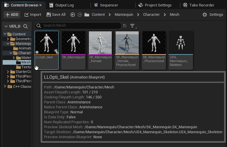
Step 4. In the content browser, assign a name to the created animation blueprint.
Step 5. Drag the character blueprint into the scene.
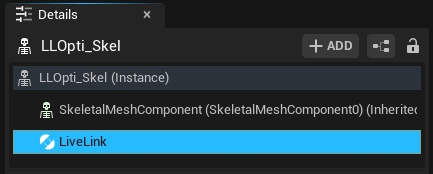
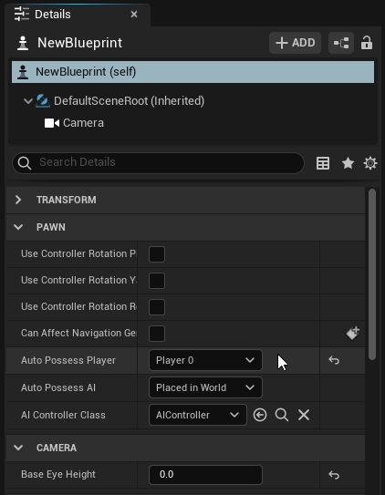
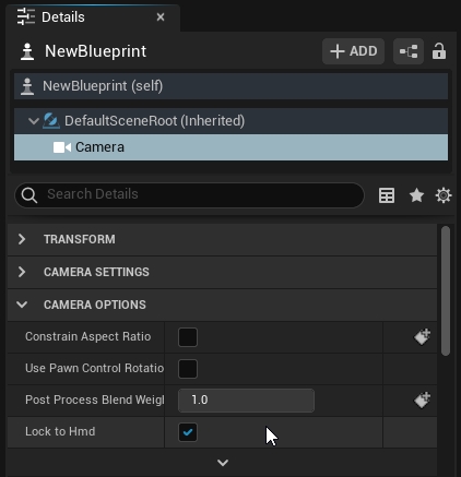
Step 6. Select the character blueprint in the 3D View
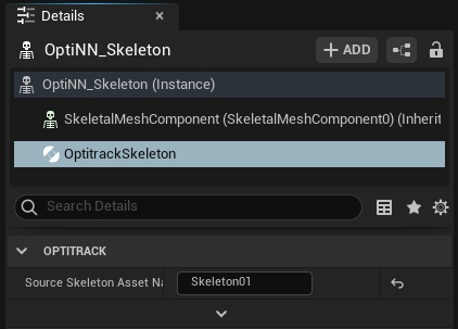
In the Details Pane, select “+ ADD” and create a new an “OptiTrack Skeleton Instance” on the model.
Set the “Source Skeleton Asset” equal to the Skeleton name in Motive.
2. Setup the Blueprint
**Step 1.**Double-click the animation blueprint in the content browser to open its editor.
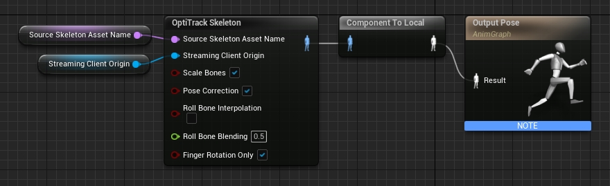
**Step 2.**Right-click the animation graph, then create a new "OptiTrack Skeleton".
**Step 3.**Right-click the animation graph, then create a new "Get Streaming Client Origin" and connect its output to the Streaming Client Origin.
**Step 4.**Right-click the animation graph, then create a new "Get Source Skeleton Asset Name" and connect its output to the Source Skeleton Asset Name.
Step 5. Right-click the animation graph, then create a new "Component To Local" and connect the output from "OptiTrack Skeleton" into its input.
**Step 6.**Connect all of the nodes together. The basic animation flow chart should look like the following.
Bone Transformation
Within the animation blueprint, you can utilize other blueprint utility tools from UE4 to modify the streamed data. For example, Transform (Modify) Bone nodes can be included after the OptiTrack Skeleton node to apply a transform to specific Skeleton bones as needed. Please refer to Unreal Engine documentation for more information on using animation blueprints.
Roll Bone Interpolation
For characters with unmapped shoulder roll bones, the Skeleton plugin will detect its existence and apply a slight twist to the roll bones to keep smooth swinging motion on the arms. In the OptiTrack Skeleton blueprint, you can enable/disable this feature from the Roll Bone Interpolation checkbox, and you can also adjust how much of twist is applied by setting the Roll Bone Blending parameter. When this parameter is set to 0, the plugin will not adjust the roll bone motion, and when this is set to 1, the plugin will attempt to adjust its motion to keep the shoulder steady on the character.
Please note that this feature may not work on some characters.
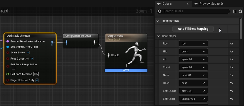
3. Assign Bone Mapping
Step 1. Select the OptiTrack Skeleton plugin in the blueprint graph area.
Step 2. Drop down the Bone Mappings property in the Details Pane.
Step 3. Click “Auto Fill Bone Mapping” to automatically assign the bones in the Skeleton to the OptiTrack Skeleton names.
Note: There is no standard for bone naming conventions, so bone names may vary depending on characters. After doing the auto-fill, review the list and double-check that the auto-assigned names are correct. You may need to manually use the drop-down menu to adjust the assigned mapping for missing, or incorrect, items.
Step 4. Hit "Compile" in the top left to build the blueprint.
4. Setup OptiTrack Streaming
Step 1. Open the 3D View
Step 2. Search OptiTrack Client Origin in the Modes pane.
Step 3. Drag the OptiTrack Client Origin into the 3D scene, then select it to access its properties.
(Optional) put it at 0,0,0 location.
Make sure that streaming settings on both Motive and Unreal match.
See: OptiTrack Unreal Engine page for more instructions on setting up the client origin.
5. Click _Play_
The OptiTrack Unreal Engine Skeleton Plugin uses bone mapping, not retargeting. This means that the bone segments in Motive map directly to the character model (bone mapping), instead of being translated into something that is usable by a more abstract biped model (retargeting). Because of this non-anatomical Skeletons will not map correctly without some additional tweaking.
Practically, this means that you will need to do things like turn off the toe mapping for characters with high heels, adjusting the pelvis bone in Motive or in the model for characters with non-anatomical hip bones, and not use bipeds that are too anatomically different than humans, such as a gorilla or swamp monster.
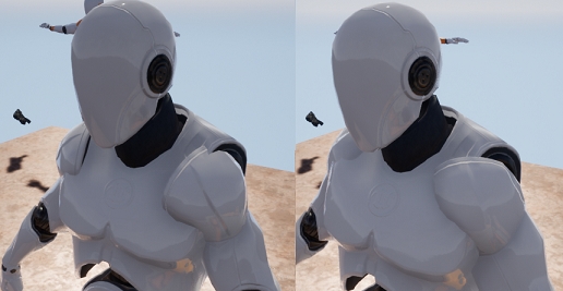
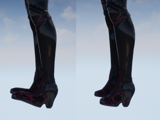
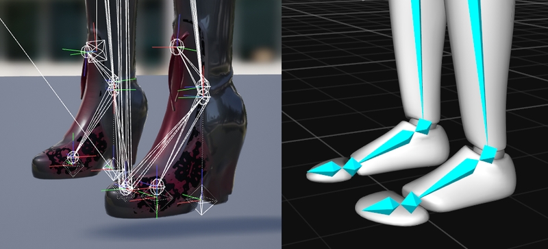
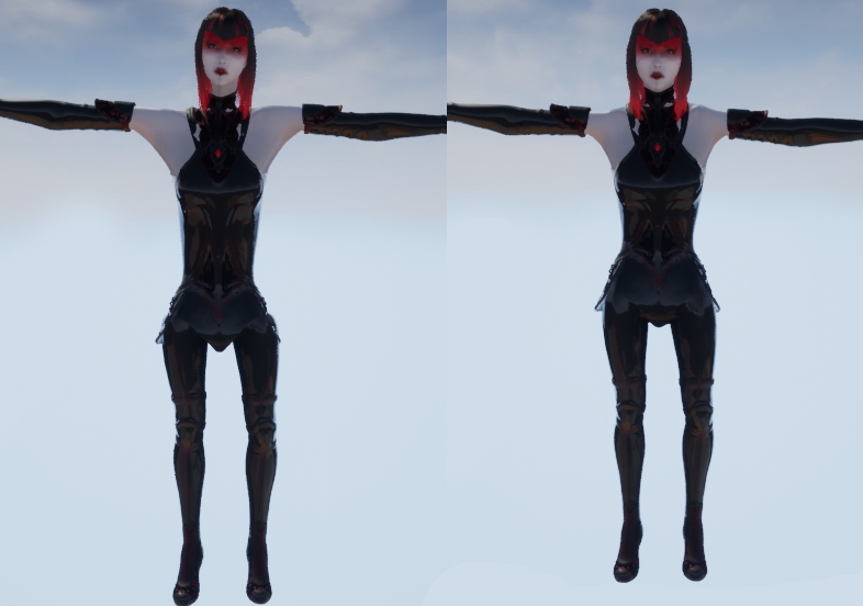
For example, the character sample below has both a non-anatomical pelvis and high heels. It is preferable to use character models that are more anatomically correct, but in this case, you can do a couple things to mitigate these issues:
1. Turn-off toe streaming
In the example below, since this character is wearing heels, any actor providing data for this model will also need to be wearing heels. To get around this you can just turn off the toe mapping in the OptiTrack Unreal Engine Skeleton Plugin.
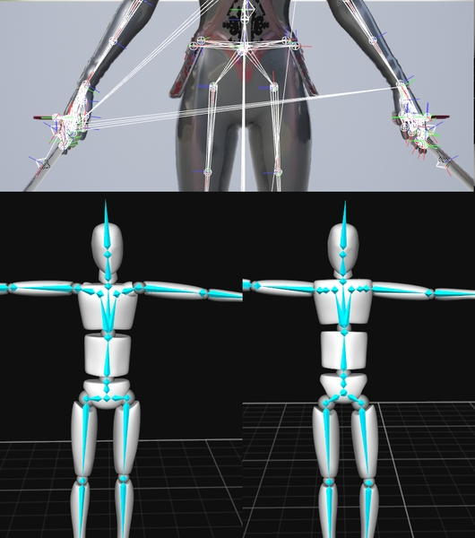
2. Adjust the bone segments in Motive
The hip segment on the Countess actor is centered in the stomach rather than in the pelvis, the neck bone in Motive is a bit too long for the model, and the shoulders in Motive do not match the width of the character’s shoulders. By adjusting bones' positions and lengths in Motive, you can make the streamed Skeleton to better match the model; however, please note that there are limitations to how much you can do this.)
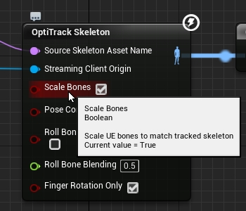
When streaming Skeleton data to animate characters that have different bone lengths compared to the mocap actor, the UE character will need to be scaled accordingly. In this case, the "Scale Bones" feature in the OptiTrack Skeleton node automatically scales the character bones to match the mocap actor. This setting is enabled by default.
The OptiTrack Unreal Engine Skeleton Plugin uses bone mapping, not retargeting. This means that the bone segments in Motive map directly to the character model (bone mapping), instead of being translated into something that is usable by a more abstract biped model (retargeting). Because of this, non-anatomical Skeletons will not map correctly without some additional tweaking. Starting from plugin version 1.23, you can tweak the alignment of the bone mapping by adding sockets to the Skeleton blueprint:
Adding Sockets to the Bone Mapping
Open Skeleton Editor of the character you wish to modify
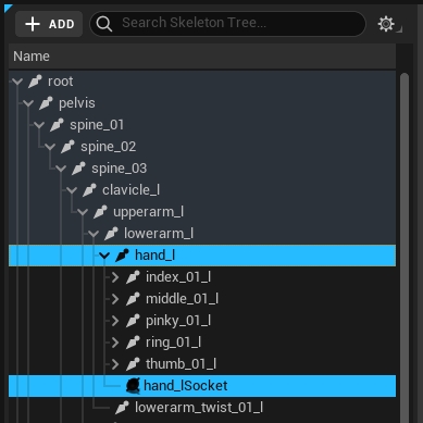
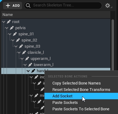
Under the Skeleton tree, right-click on the bone that you wish to add the sockets to.
Right click and select_Add Socket_.
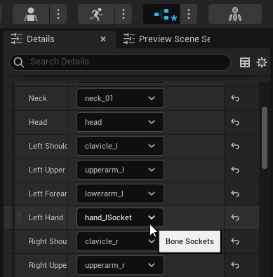
Go to the Animation blueprint, and change the bone mapping of the bone which you have created sockets for, and map it to the socket that was just created.
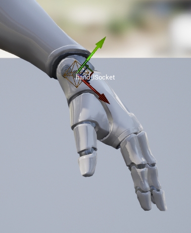
Play the scene, and adjust the socket location from the Skeleton Editor to adjust alignment of the bone.
Use the Live Link Hub to stream OptiTrack camera data to the UEFN plugin for video game development in Fortnite.
The OptiTrack Live Link Hub plugin allows game designers to use OptiTrack Motion Capture data to animate characters in Fortnite through Unreal Editor for Fortnite (UEFN).
Download the latest Unreal Engine 5 Plugin from the .
Open the Epic Games Launcher. The following Epic Games applications must be installed:
Unreal Engine 5.5
Live Link Hub
UEFN
Fortnite
Launch Unreal Editor for Fortnite (UEFN).
Select Live Link Hub from the Tools menu, if it's not already open.
Click the Settings button in the upper right corner and select Plugins...
In the User Plugin Directories section, click the Add Element button.
Click the ellipses button to browse to and select the downloaded plugin.
Restart UEFN when prompted after the plugin is installed.
In the NatNet section, select Enable to begin streaming.
Select the Local Interface. Use Loopback if streaming to the same computer, otherwise select the IP address for the network where the client application resides.
Set the Bone Naming Convention to UnrealEngine.
Set the Up Axis to Y-Axis. The plugin will bring the data in with a Y-Forward orientation.
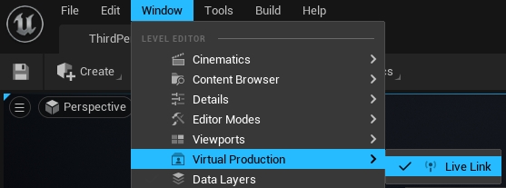
In Unreal Engine, open Live Link Hub from the Tools menu on the toolbar, if it's not open already. Under Virtual Production, select Live Link Hub.
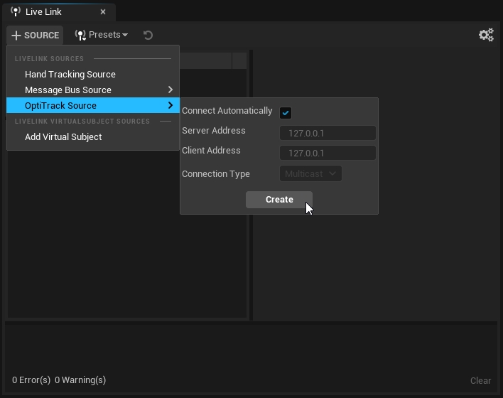
Select OptiTrack Source, check Connect Automatically, or enter the IP address for the Motive PC in the Server Address field, the IP address for the Unreal PC in the Client Address field. Enter 127.0.0.1 in both fields if running both on the same PC. Click create.
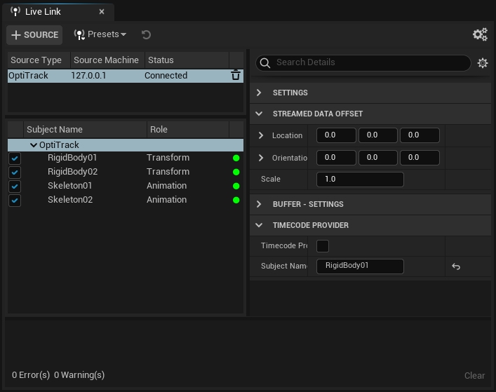
Properties are shown in the Source Details tab when the OptiTrack source is selected. The properties that are applicable to Fortnite characters are listed below.
Adjust the location, orientation, or scale of the streaming data.
Timecode is fully supported in the plugin. Click the button in the top right to use preset system time codes or add a new Timecode Provider in the Source Details tab.
Timecode data may appear to stutter in Unreal Editor even when it is transmitting correctly. To confirm that the data is in sync, compare the timecode in Live Link Hub to the timecode in Motive.
Unreal Editor for Fortnite does not support the display of markers.
We recommend using Windows Explorer to copy assets into the project folder. Right-click the project folder in the Unreal Editor Content Browser and select Show in Explorer.
In the Content Browser, copy the following files and folders from All > Engine > Plugins > OptiTrack - Live Link Content > Animations to the project folder:
Female Avatar (folder)
Male Avatar (folder)
Textures (folder)
IK_MotiveAvatar_Opti.uasset (file)
SK_MotiveAvatar_Opti.uasset (file)
The T-Pose asset and animation blueprints typically used in Unreal Engine are not supported in Unreal Editor.
Unreal Editor will validate the project files before launching the live session.
All skeletons in Unreal Editor are based on the standard Fortnite mannequin. Animation is applied to the mannequin rather than using an animation blueprint. In this example, we will use the Fortnite Mannequin to build an IK Rig to receive data from the OptiTrack skeletons.
Before creating our IK Rig, drag the Motive Avatar of your choosing into the scene to prep the retarget phase.
To create the IK Rig:
Right-click in the Content area. Select Animation > Retargeting > IKRig.
Name the IKRig. We recommend IK_FNMannequin.
Double-click the newly created IKRig to edit it. This will open in a new window.
In the Details tab, change the Preview Mesh to the FN Mannequin.
The mannequin is pre-configured to work with Fortnite. This allows you to use the Auto Create features in the upper left corner to finish setting up the IK Rig.
Click the Auto Create Retarget Chains button.
Click Auto Create IK.
Click Reset.
Click Save.
The IK Rig is now configured and the tab can be closed.
Right-click in the Content area. Select Animation > Retargeting > IK Retargeter.
Name the IK Retargeter. We recommend RTG_Motive_FN.
Open the newly created Retargeter.
On the Details tab, go to Source > Source IKRig Asset.
Use the dropdown list to select the standard Motive avatar, IK_MotiveAvatar_Opti.
The Viewport will show that the two skeletons are not properly aligned. This occurs because the skeletons are in different poses.
Click the Running Retargeter button in the upper left corner to stop the retargeter and switch to edit mode. The button will update to Editing Retarget Pose.
Set the Retargeter back to Run mode for the remaining steps.
To complete the next step, it's easiest if only the mapped bone chains are visible.
In the Chain Mapping pane, click the Settings button and select Hide Chains Without IK.
Select all of the mapped Chains.
In the Details tab, go to IK > Blend to Source.
Set the value to 1.0.
Go to Blend to Source > Blend to Source and set the value to 1.0.
The retarget will now display correctly in the Viewport. This window can now be closed.
From the Content Browser, drag the skeletal mesh for the Fortnite mannequin into the scene. The mannequin is located in All > Fortnite > Characters > PlayerBasics.
Both the Motive Avatar and the Fortnite Mannequin will be in the scene.
Select the Motive Avatar.
In the Details tab, go to Performer > Performance Capture > Subject Name.
Select a performer from the list of actors in Motive.
The Motive Avatar will now animate with the selected actor.
Select the Fortnite Mannequin to display its properties in the Details pane.
Once the Retarget Component is attached to the Mannequin, update the following properties in the Retarget section:
Source Skeletal Mesh Component: Select the Motive Avatar.
Controlled Skeletal Mesh Component: This should already be set to the Fortnite Mannequin.
The Avatar and Mannequin will animate in realtime only in the Editor, not in the game.
In the Outliner pane, drag the Mannequin to nest under the Motive Avatar.
In the Details pane for the Mannequin, go to Transform > Location and reset the values to 0.
The Avatar and the Mannequin will be aligned.
Once all of the characters are configured, the next step is to record the animation using the Take Recorder and Sequencer in Unreal Editor.
To open either pane, go to the Windows menu > Cinematics.
Type the project name in the Slate field.
Select From Actor > Add 'Device Mannequin'.
With the Mannequin selected, update the following properties:
Disable Transform > Transform Track.
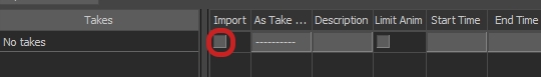
Disable Animation Recorder > Remove Root Animation (shown below).
Go to User Settings > Countdown to include a countdown timer to start recording.
To begin recording, click the large red Play button on the right edge of the Slate in the Take Recorder:
When the recording is completed, click the Review button in the Take Recorder pane.
The character will now animate as expected.
You can find the Take and the associated animations in the Cinematics folder in the Content Browser. Takes are organized with a folder for each subscene. The animations recorded in that subscene are stored in an Animation folder, one for the Device Mannequin and one for the Motive Avatar.
Now that the animation has been created and aligned to the Device Mannequin, it's time to apply it to a Fortnite character. Since all characters in Fortnite use this same skeleton, no additional alignment is required.
Fortnite has a large selection of characters available, all based on the Device Mannequin skeleton. To add a character to the scene from the Content Browser:
Go to Fortnite > Devices > AI.
Drag the Character Device to the scene.
Select the Character Device in the Viewport.
Go to Fortnite > Characters and select the desired character from the gallery.
In the Details pane for the newly added Character Device, drag the Fortnite character you wish to use to User Options > Character.
Select the Fortnite character in the Viewport.
Under User Options, check the box for Custom Idle.
Drag the Device Mannequin animation from the Content Browser to the Custom Idle field.
Fortnite will update the game in Edit Mode, with the status displayed in the upper right corner. The game will move through the following phases: Preparing; Loading Project; Downloading; and Connecting (displayed on the Edit Session screen). When the game loads, the status will be Up to Date.
The animation will play on the Fortnite character when the game starts. It will not play in the editor. To see this, you can start the game from UEFN or inside Fortnite itself.
Setup guide to stream video cameras from Motive using the Camera Role in Unreal Engine.
Motive’s Live Link plug-in for Unreal Engine includes the ability to stream tracked rigid bodies for Virtual Production and InCamera VFX (ICVFX).
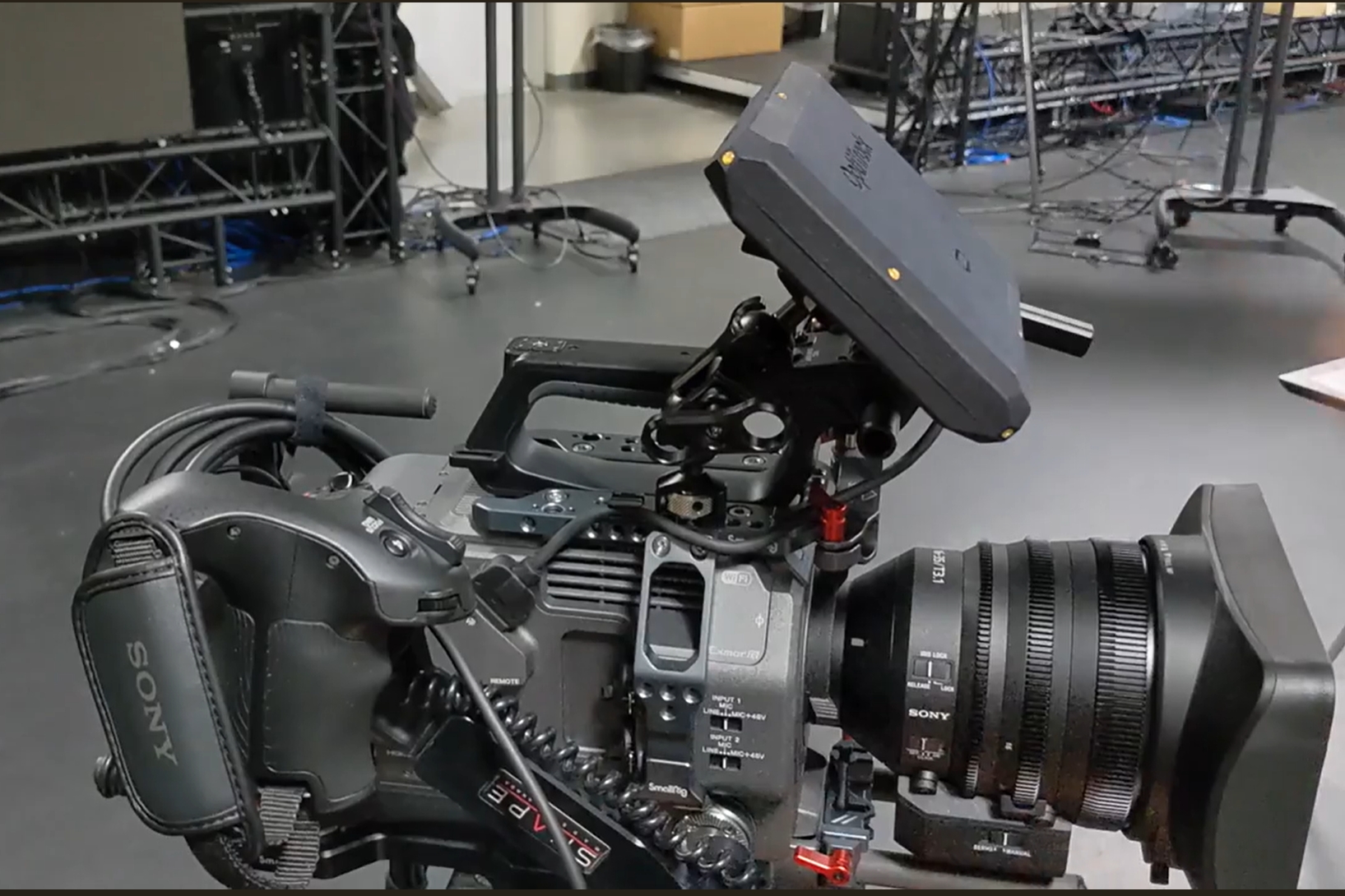
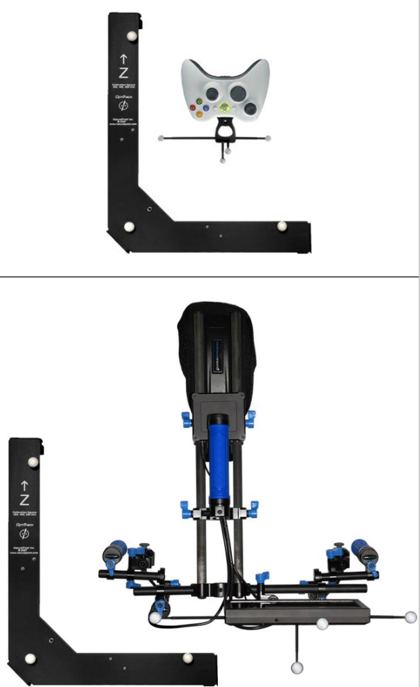
Motive tracks video cameras using a CinePuck, an active device equipped with an IMU. The CinePuck mounts directly to the video camera and, when aligned with the camera lens as a Rigid Body, tracks the camera's focal point so it can be replicated virtually in the Unreal Engine environment.
The Camera Role in Unreal Engine can now be used for the Tracked Camera Rigid Body. This means that you can now connect a lens file with the associated Live Link Camera Role Asset. In Unreal Engine, users can calibrate for lens distortion and nodal offset, and use the camera with a Lens Encoder, if desired.
This document provides instructions to setup and link a Rigid Body in Motive to a Live Link Camera Role in Unreal Engine. For information on ICVFX production in general, please see the page .
We used the standard InCameraVFX template in Unreal Engine for our sample project. The template includes all the necessary macros and assets needed for virtual production.
This template is located under Film / Video & Live Events in the Unreal Project Browser.
Motive will stream the camera as a Live Link Rigid Body asset.
Plug the into one of the Power over Ethernet (PoE) switches on the OptiTrack camera network.
Firmly attach the to the Studio Camera using the SmallRig NATO Rail and Clamps on the cage of the camera.
The CinePuck can be mounted anywhere on the camera. For best results, put the puck closer to the lens.
Power on the CinePuck, and let it calibrate the IMU bias. The lights will flash red and orange during calibration and change to green when done.
We recommend powering the CinePuck with a USB cable while filming to avoid running out of battery power. A light on the CinePuck will indicate when the power is connected.
Select OptiTrack Source, check Connect Automatically, enter the IP address for the Motive PC in the Server Address field, the IP address for the Unreal PC in the Client Address field, and click Create. Enter 127.0.0.1 in both fields if running both on the same PC. Leave the Connection Type as Multicast and click create.
This will display a list of assets streaming from Motive. Note that the rigid body camera, named HandCam2, is currently in the Transform role.
Click OptiTrack in the Subject list to display the OptiTrack Live Link Properties.
In the Live Link Roles section, click the Live Link Subject dropdown. This will open the list of Assets streaming from Motive.
Select the camera asset, HandCam2 in this example.
Directly below the Live Link Subject field is a check box to Stream as Camera (Rigid Bodies Only). Check this box to apply the Camera Role to the camera rigid body (HandCam2).
Move all the NDisplay assets to nest under OptitrackLiveLinkDisplay in the Outliner pane.
Select the video camera, now nested under OptitrackLiveLinkDisplay in the Outliner pane..
Search for and select the Live Link Controller component.
Properties for the new Controller will display in the Camera details pane.
Click the dropdown next to Subject Representation and select the camera Rigid Body.
The Subject and Role fields will both update to display the name of the Rigid Body name.
The LiveLinkController label can only be applied to Rigid Body assets.
As noted above, Unreal Engine includes properties that allow you to calibrate a video camera streaming into Unreal Engine. This includes the ability to use a lens encoder with the camera.
When using a Lens Encoder or a calibrated Lens in Unreal Engine, use the Lens File Picker settings to select the appropriate Lens File.
For our streaming applications, Unreal Engine 4 and 5 have essentially the same setup. The main difference is the UI and where to find the appropriate settings and buttons. All our guides on this Wiki have been updated to feature Unreal Engine 5. If you need assistance with Unreal Engine 4 please feel free to reach out to our team.
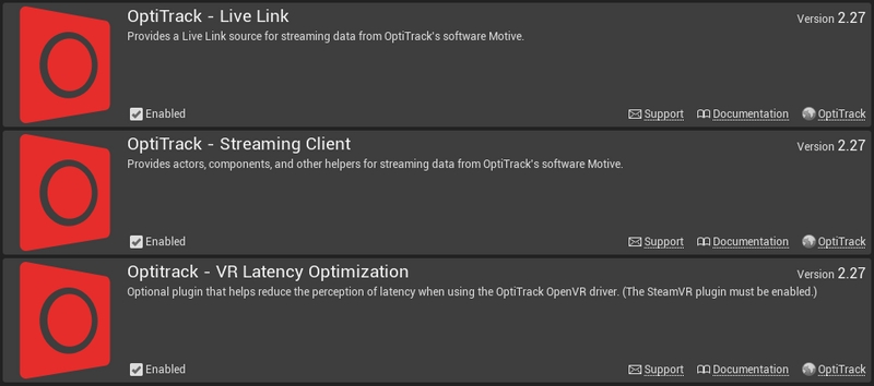
The allow you to stream real-time tracking data from Motive into Unreal Engine. This includes tracking data of Rigid Bodies, Skeletons, and HMDs that are tracked within Motive. This article focuses on the organization of those plugins. For basic instructions on setting up a motion capture system, please refer to the guide instead.
OptiTrack - Live Link
OptiTrack - Streaming Client
Both of these plugins are included in the ZIP file.
For plugin version 1.23 and above, support for Oculus HMDs has been deprecated.
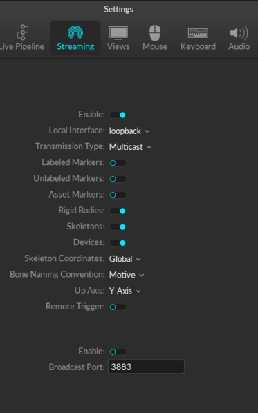
First, you'll want to follow the below instructions to set up the data streaming settings in Motive. Once this is configured, Motive will be broadcasting tracking data onto a designated network interface where client applications can receive them.
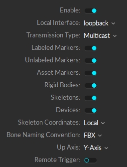
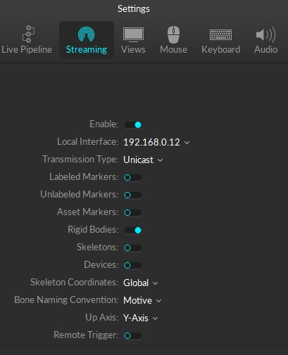
Enable - Turn on the Enable setting at the top of the NatNet section.
Local Interface - Choose the desired IP network address from this dropdown to stream data over.
Loopback
This is the local computer IP address (127.0.0.1 or Localhost).
Used for streaming data locally on the PC you are running Motive on that does not interact with the LAN.
Good option for testing network issues.
192.168.0.1x (typical, but may be different depending on which interface is used to establish a LAN connection)
This IP address is the interface of the LAN either by Wi-Fi or Ethernet.
This will be the same address the Client application will use to connect to Motive.
Transmission Type
For streaming over a Wi-Fi network, setting the Transmission Type to Unicast is strongly advised.
Select desired data types to stream under streaming options:
Rigid Bodies - Enabled (required).
Skeletons - Optional for Skeleton tracking.
Markers (Labeled, Unlabled, Asset) - Disabled for HMDs (advised).
Devices - Disabled.
Skeleton Coordinates
Set to Local.
Bone Naming Convention
Set the appropriate bone naming convention for the client application. For example, if the character uses the FBX naming convention, this will need to be set to FBX.
Additional Tips
For best results, it is advised to run Motive and Unreal Engine separately on different computers, so that they are not competing for processing resources.
When streaming the data over a wifi network, Unicast transmission must be used.
In order to stream data from the Edit mode, a capture-recording must be playing back in Motive.
OptiTrack motion capture systems can be used to track head mounted displays (HMD) and integrate the tracking data into Unreal Engine for VR applications. For instructions on integrating HMD tracking data into Unreal Engine, please refer to the corresponding page:
Supported HMDs
At the time of writing, the following HMDs are supported:
HTC VIVE
HTC VIVE Pro 1/2
Valve Index
HP Reverb G2
Deprecated support for Oculus HMDs:
Support for Oculus Integration have been deprecated starting from UE plugin version 1.23; Plugin version 1.22 or below must be used for Oculus HMDs.
Vive and Valve Index HMDs are supported through the OpenVR driver.
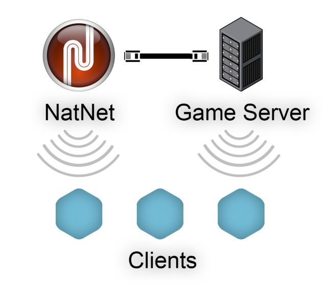
When setting up multiplayer games on wireless clients, it is more beneficial for each client to make direct connection to both the tracking-server (Motive) and the game-server, rather than rebroadcasting the streamed tracking data through the game-server. Then, any of the game related actions that interacts with the tracking data can be processed on the game-server, and this server can send out the corresponding updates to the wireless clients. This allows the wireless clients to only receive both the tracking data or updates without having to send back any information; in other words, minimizing the number of data transfers needed. If wireless clients are sending data there will be a minimum of two transfers on the wireless network, and each transfer of data through wireless network is at risk of latency or lost packets.
Learn how to use the Active Puck Static Meshes included in the Live Link Plug-in Content folder.
OptiTrack's plugin for Unreal Engine includes an array of content options. the 5.3 plugin includes the following new content:
ActivePuckMesh
CinePuckMesh
MotiveAvatarMesh
MotiveSkeletalMesh
MotiveSkeleton
This page covers the Active Puck and CinePuck static meshes, using the Active Puck as the example.
The Active Puck Mesh provides a couple of different use cases:
Data validation. Tracking an active puck in the physical volume using the OptiTrack Live Link display provides a point of reference that allows you to validate rotation, placements, and even the scale of your volume.
We used the standard InCameraVFX template in Unreal Engine for our sample project. The template includes all the necessary macros and assets needed for virtual production.
This template is located under Film / Video & Live Events in the Unreal Project Browser.
This section walks the user through adding the puck static mesh to a project and aligning it with the puck streaming from Motive.
Check the boxes for Show Engine Content and Show Plugin Content.
The Content Browser’s Navigation pane will now show the Engine Content, where the Plugins folder resides.
Open the OptiTrack—Live Link Content folder.
Open the ActivePuckMesh folder. If using a CinePuck, open the CinePuckMesh folder .
The Live Link asset automatically aligns with its source in Motive. The Markers settings display a visual map of the marker locations. This map is helpful for confirming the alignment of a static mesh to a streamed asset.
In the Live Link pane, select OptiTrack.
In the Markers section of the OptiTrack Properties pane, set Create Labeled Markers to true.
To open the Live Link pane, select Virtual Production → Live Link from the Window menu.
Right click in the Content Browser to open the menu.
Under Create Basic Asset, select Blueprint Class.
Select Actor as the Parent Class.
Open the newly created Blueprint linked to the puck streaming from Motive.
Double-click the newly created static mesh in the list of components to rename it. In our example, we called it ActivePuck.
Select the static mesh in the Components pane to display its properties in the Details pane.
Click the Static Mesh property (set to None by default) to select the asset to use.
Select SM_ActivePuck_Opti for the Active Puck, or SM_CinePuck_Opti if using a CinePuck.
The Active Puck static mesh will now appear in the scene.
An Active Puck can serve as a lens calibration device in Unreal Engine by aligning calibration points to the markers at each of the four corners.
For accuracy and precision, use the Top view in the UE Viewport.
Search for and select Calibration Point from the list of options.
Click to rename the Calibration point. We recommend using names that match the point's location, such as top left, bottom right, etc.
Drag the newly created point to align it with the center of the corner marker.
Use Ctrl + D to Duplicate the point to make the next one.
Rename the second point and drag it to the appropriate location, aligning it with the previously placed point on either the X or Y axis.
Repeat these last two steps until each of the four corners has a Calibration Point at its center.
Select the ActivePuck in the list of components. The four calibration points should be nested underneath.
Click the Compile button on the main toolbar, then Save and Close the tab for the Blueprint.
In the project, click and drag the Blueprint created in the prior steps into the project.
In the Outliner pane, drag the Blueprint under OptiTrackLiveLinkDisplay.
Under Subject Representation, click and select ActivePuck from the list of available assets (below, left).
This will link the static mesh to the puck. The Labeled Markers setting shows the device properly aligned (below, right).
Use the translate tool to reorient the static mesh if the OptiTrack brand and the status lights on the mesh do not align with those on the physical puck.
The puck is now available as a tracked calibrator tool that can be used in conjunction with a lens file in Unreal Engine for lens calibration.
Right click in the Content Browser in the folder where you'd like to save the lens file.
Search for and select Lens File from the list of Content types and give the file an appropriate name, such as 35mm_Lens.
Open the Lens File.
Click Lens Distortion on the Calibration Steps tab.
In the Lens Distortion Algo setting on the right, select Lens Distortion Points Method.
The Calibrator setting will default to the calibrator puck.
Select the current calibrator point in the camera viewport to complete the alignment.
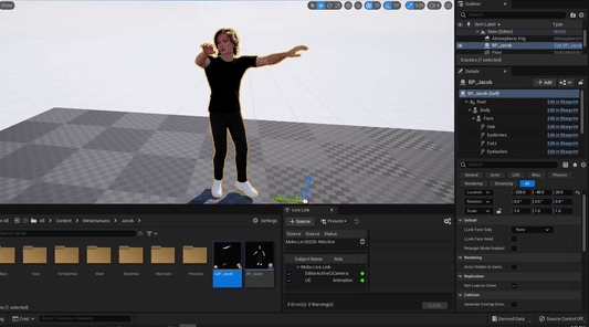
This guide will cover how to get motion capture data streamed from Motive to Unreal Engine 5's MetaHumans with the additional help of MotionBuilder.
A method commonly used in Virtual Production pipelines, uses MotionBuilder to manually retarget the bones and source the streamed data from Motive onto a MetaHuman. Additionally, this process allows for more refined cleanup through MotionBuilder if required in the future.
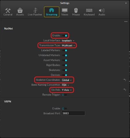
Turn on the Enable setting at the top of the NatNet section to enable streaming in Motive.
It is recommended that Motive and MotionBuilder should run on the same machine. An additional machine should be used to run Unreal, since UE5 can be resource intensive.
Set to Loopback. This is the LocalHost IP since Motive and MotionBuilder will be running on the same machine.
Set to Multicast
Select which markers you'd like to stream into UE5, you will need to at least have Rigid Bodies and Skeletons enabled.
Set to Global.
Set to FBX
Set to Y-Axis
Leave unenabled
Be sure to either actively playing a looped take, or stream a live skeleton in Motive so the plugin can capture the data and send it to MotionBuilder.
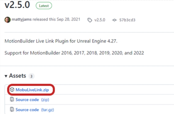
Once downloaded, you can extract the Zip folder and go to MobuLiveLink > Binaries > MobuVersion.
You'll want to then copy those three files in this folder and paste them in to the C:\Program Files\Autodesk\MotionBuilder 2020\bin\x64\plugins. file directory folder.
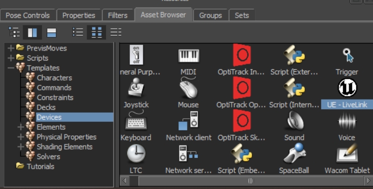
Once these files are added to the file directory folder, it should appear as UE - Livelink in Devices under the Asset Browser in MotionBuilder.
It's best to enable both the Quixel Bridge and OptiTrack Live Link plugins together, since you'll likely need to restart Unreal Engine each time you enable a plugin.
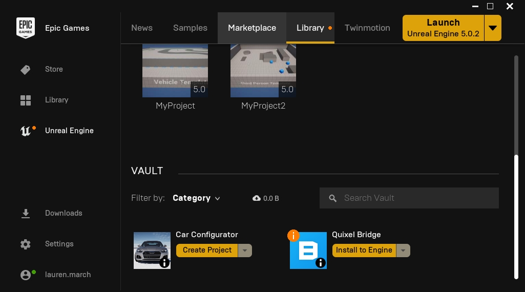
First, you'll want to verify that the Quixel Bridge plugin is installed with Unreal Engine 5. You can install the Quixel Bridge plugin from the Epic Games Launcher by clicking Unreal Engine then the Library Tab.
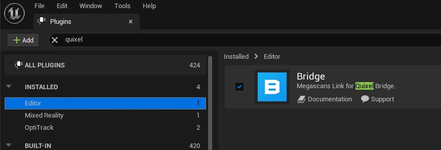
You'll also wan to make sure that the Quixel Bridge plugin is enabled. To do this go to Edit > Plugins > Editor and click the check box. You may have to restart Unreal after enabling this plugin.
Next, you'll want to create a project to import your MetaHuman into. Once, your project is created, open Quixel Bridge within your Unreal project.
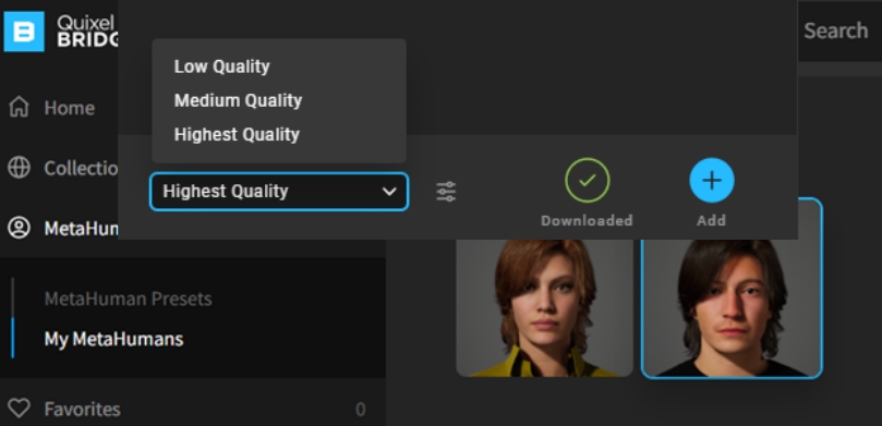
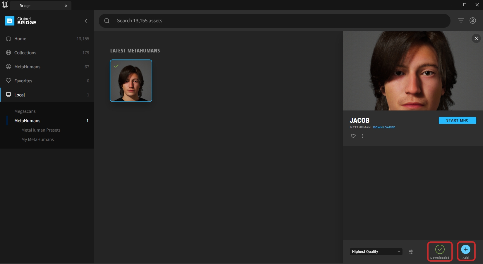
Now that you're in the Quixel Bridge window, log in to your MetaHuman account and navigate to MetaHumans > My MetaHumans.
Select the MetaHuman you wish to load into the project and select the desired quality profile. Then click 'Download'. After is has completed downloading, you will be able to add it to the current project.
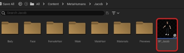
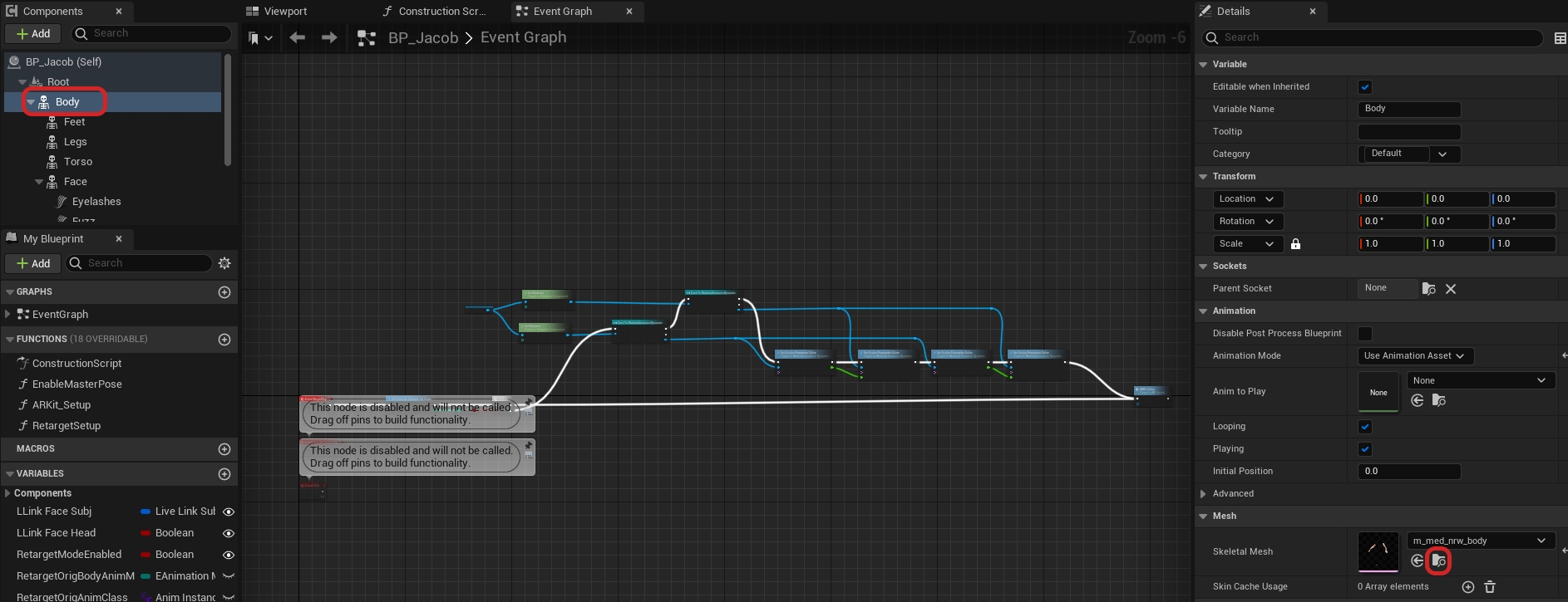
Navigate to the MetaHuman blueprint in the Content Browser under Content > MetaHumans > "MetaHumanName" > BP_MetaHumanName and double click to open the blueprint window.
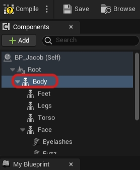
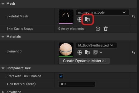
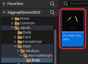
In the Components tab on the left, select Body then navigate to the Skeletal Mesh tab of the Details node. Choose which Skeletal Mesh you'd like to use.
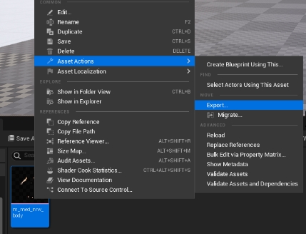
Exit this window and find the mesh in the content browser and right click and select Asset Actions > Export....
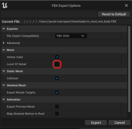
Select FBX Export and deselect Level of Detail in the FBX Export Options.
Now that the skeleton driving the MetaHuman is exported, we can retarget animation in MotionBuilder from the OptiTrack plugin.
In MotionBuilder select File > Open and select the MetaHuman you exported earlier.
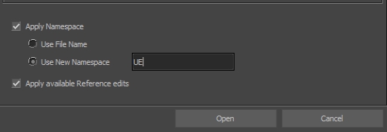
Apply a namespace, this will prevent this skeleton from conflicting with any other potential skeletons in the scene.
You do not need to import any takes with this file.
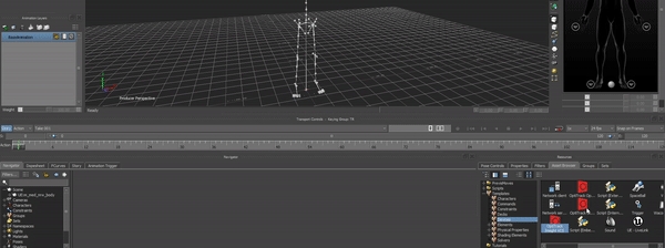
The Skeleton should now appear in your scene/viewport.
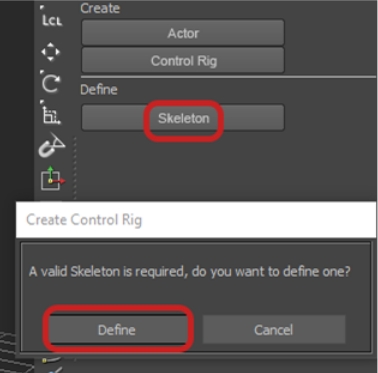
Under the Character Controls panel, select Skeleton > Define under the Define tab.
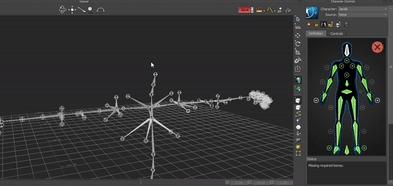
To fill out this definition quickly, select the bone you want to map first in the viewport and then in the Definition panel right click and hold on the bone.
Hover over Assign Selected Bone then let go of right click.
Repeat that process for all the Main Bone Hierarchy.
There’s no need for any extra bones in the definition, for example “ Spine_04_Latissimus_r” as Motive’s skeleton does not drive any of those bones.
You'll want to make sure that the MetaHuman skeleton is in a T-pose. If hand tracking will be added too, make sure to pose the hands in the proper pose for said hand tracking application.
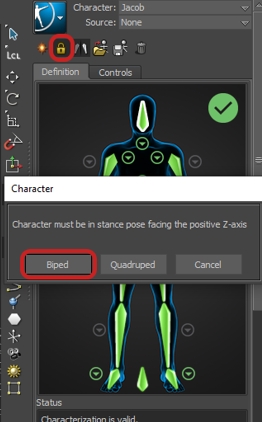
When all the bones are filled out in the definition and the skeleton is in T-pose there should be a green checkmark notifying everything is ready to characterize.
To lock in the definition, click the lock at the top of the Character controls panel. Now that the character is created, the respective plugins can be added to the scene that will drive the streaming into Unreal.
In MotionBuilder go to the Asset Browser pane select the Device from the Peripherals dropdown. Drag and drop the OptiTrack Skeleton and the UE5 Live Link plugins into the main viewport to add it to the scene.
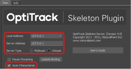
From the navigator tab on the left, select OptiTrack Skeleton from the I/O Devices dropdown. This will open the Main tab of the OptiTrack Skeleton plugin's settings.
Set both to 127.0.0.1
Set this to match was was selected in Motive (either Unicast or Multicast)
Make sure to check this box to enable Auto Characterize
Click this box to enable streaming in MotionBuilder:
Green - Connected and streaming.
Yellow - Connected but not streaming.
Red - Not connected or streaming.
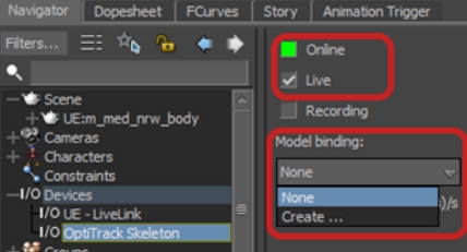
Check this box if streaming Live data
Click Create... and select the actor from Motive you wish to track
Click this box to enable streaming in UE
Green - Connected and streaming.
Yellow - Connected but not streaming.
Red - Not connected or streaming.
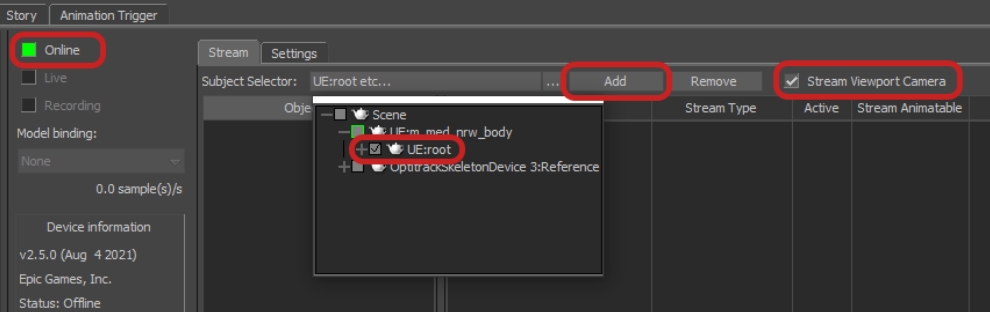
Click the dropdown and select the root of your MetaHuman skeleton.
Click Add.
Select Stream Viewport Camera if you want to stream your viewports camera to the preview section in Unreal Engine
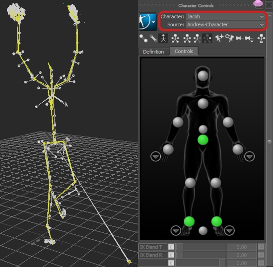
In the Character Controls panel, select the MetaHuman as the Character and the Motive Actor as the Source.
You should now see the MetaHuman skeleton copying the data that the Motive Skeleton is using.
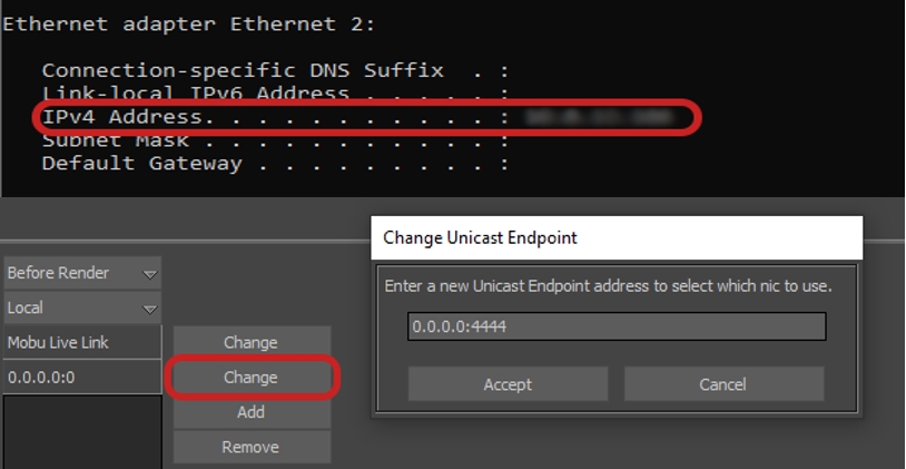
In the Settings tab in the UE Live Link Device, go to the Unicast Endpoint section, and change the address to the MotionBuilder machine's IPv4 address and choose a port number denoted by a colon after the IPv4 address.
To find the IP address of your computer, open a Command Prompt window, type in 'ipconfig' and hit enter. This should display all the networks on your computer, scroll and find the Ethernet adapter card associated with the NIC that you'll be using to connect to the network.
Port 6666 is reserved and cannot be used for endpoints.
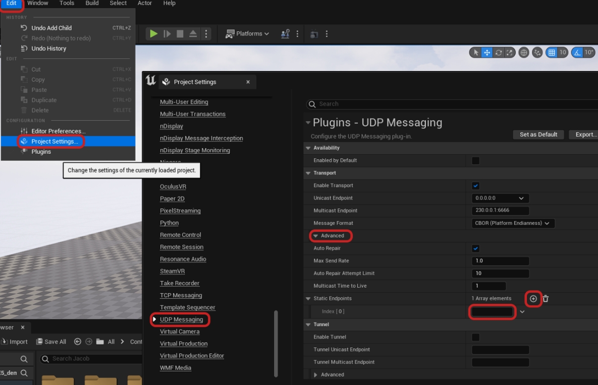
In Unreal on the computer receiving the stream, open:
Project Settings > UDP Messaging >Advanced > Static Endpoints > + to add an Array Element and enter the IPv4 address and port number from the previous step.
This will allow MotionBuilder to Live Link to Unreal Engine as normal.
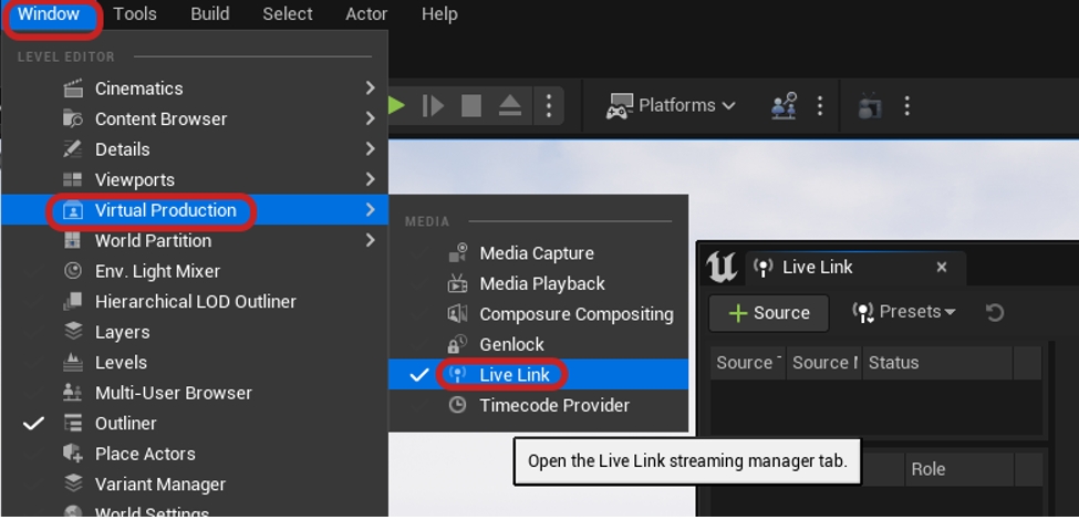
Open the OptiTrack Live Link plugin downloaded earlier. Navigate to Window > Virtual Production > Live Link.
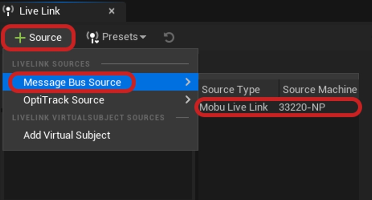
In the Live Link tab, create a new MotionBuilder source by selecting Source > Message Bus Source > MoBu Live Link.
Now that the Live Link connection has been established, the motion data from MotionBuilder can now be streamed into the MetaHuman via an animation blueprint.
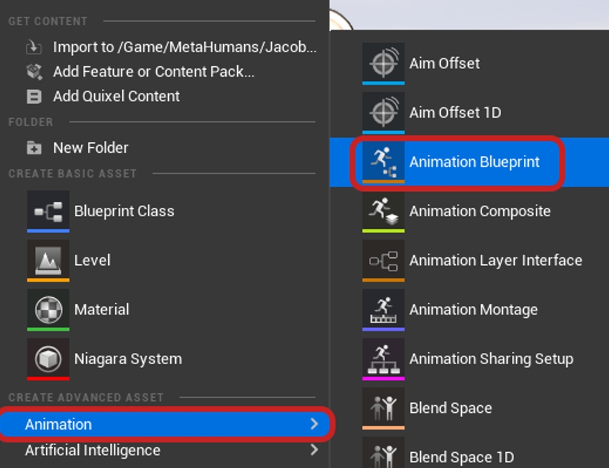
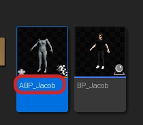
Right click in the content browser where you want to create an animation blueprint and choose Animation> Animation Blueprint.
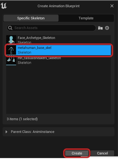
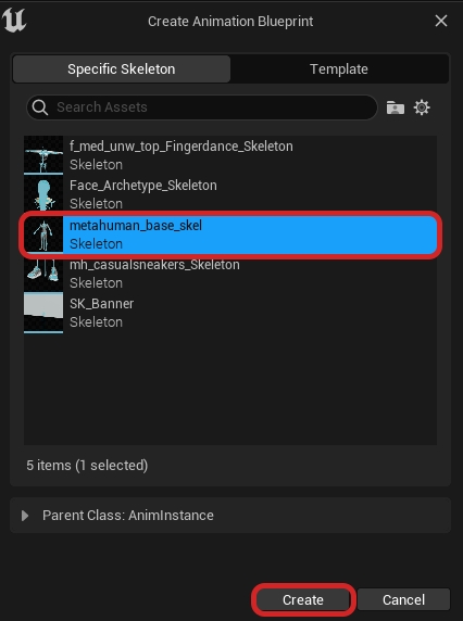
Unreal will then prompt you to choose a specific Skeleton asset. For this choose the metahuman_base_skel and click Create and name it ABP_”metahuman name”.
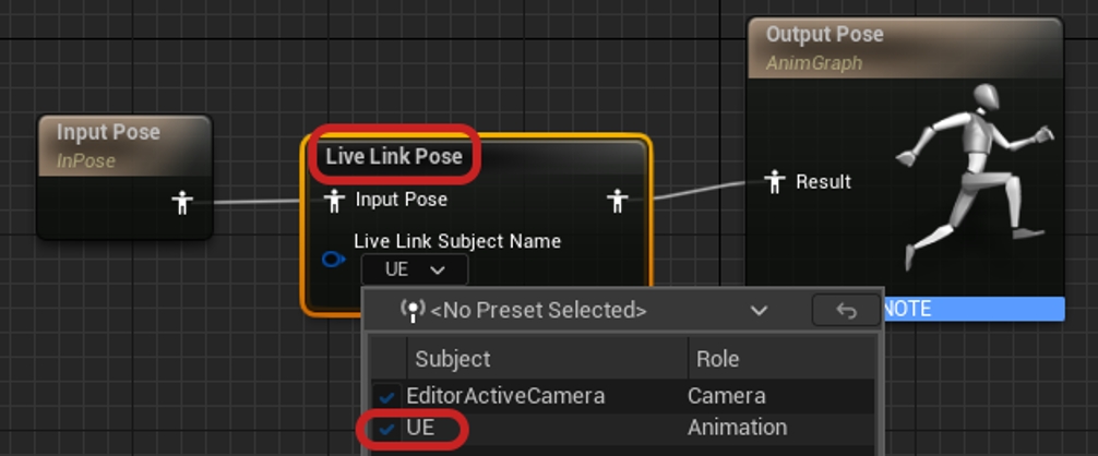
Now open the animation blueprint and in the AnimGraph create a Live Link Pose node and select the subject name as UE. Then simply hit Compile and Save.
You do not need to have an Input Pose node in the anim graph in order for it to work, however, if you would like to place one simply right click and search for Input Pose.
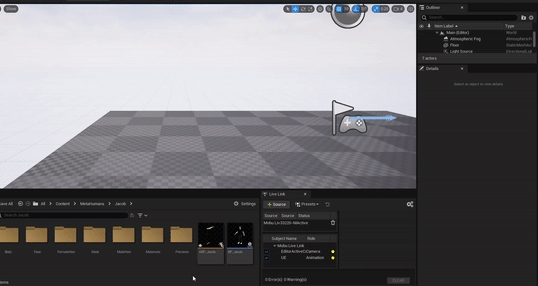
Lastly, Place the MetaHuman into the scene, select the MetaHuman and go to the Details panel on the right of the viewport. Find and select Body, then scroll down to find the Animation tab. In Animation Mode **** select Use Animation Blueprint and in Anim Class select the Animation Blueprint that you made.
If your animation data is streaming in, you should see your MetaHuman snap to a position notifying that it updated. If you would like to view the data in the edit viewport, go to the details panel again and add a Live Link Skeletal Animation.
And that’s it! With this method you’ll be able to easy make changes in MotionBuilder where you see fit, or make adjustments in the Animation Blueprint that is driving the streamed data.
To enable streaming in Motive, click the button to open the panel, then select the tab, or use the button in the right corner of the to open the Streaming tab directly.
Please see the page for more details on all settings available for streaming.
Click the button in Live Link Hub to add a new Live Link source.
Once the required assets are copied to the project folder, click the button. Unreal Editor will prompt to Save Selected, with all unsaved content selected by default.
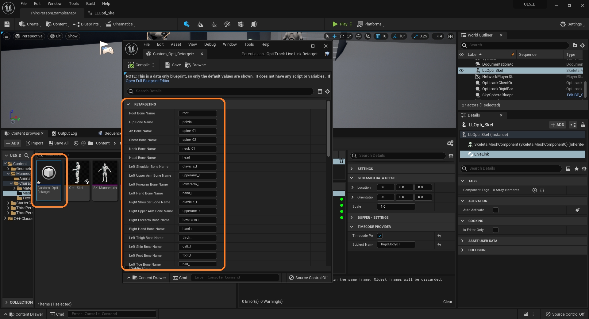
In the Target section, set the Target IKRig Asset to the , IK_FNMannequin.
Click the Auto Align button and select Align all Bones to complete the alignment.
Click the Root Settings button in the top right corner.
Click the Add button to add the Performer component.
Click the Add button and use the search bar to find and add the Retarget Component.
Retarget Asset: Select the created in an earlier step (RTG_Motive_FN in our example).
Click the Push Changes button to save the change into the Fortnite game.
With the Mannequin selected, click the add source button.
Recorded tracks will show in the Sequencer tab. Click the Stop Recording button when done recording.
Click the Push Changes button to save and update the game.
A CinePuck is tracked in Motive as a Rigid Body asset. For detailed instructions on creating a , Please see the page. For instructions on pairing the IMU, please see the page.
In Unreal Engine, click the button on the Live Link tab to add a new Live Link source.
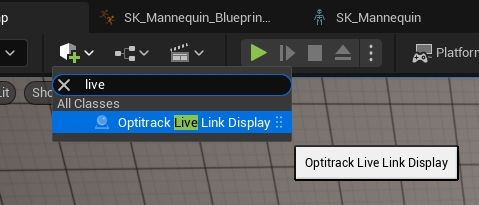
Click the Quick Add button and start typing OptiTrack over the menu to activate the search function. Select the OptiTrack Live Link Display from the list of available options.
In the Details pane, click the Add button to add a new component to the camera.
Please see for more information on calibrating cameras and working with lens files in Unreal Engine.
A variety of head mounted displays (HMDs) can be integrated using the .
Open the in Motive's Settings window and set the following settings:
For additional information on data streaming in general, read through the page.
Lens calibration device. Because the static mesh is the same scale as a real puck, its markers can be used for calibration purposes. Please see the section , below, for more details.
From the Content Browser window, click the button.
Double-click the name to give it a more meaningful name. In our example, we renamed the component BP_CalibratorPuck. We will use this puck later to create a .
This will open a new tab. Click the Add button in the top left of the Component pane and select Static Mesh from the list of options.
Select the Active Puck in the Viewport and click the Add button on the Components tab.
In the Transform Section of the Details pane, click the button to the right of the Location settings to reset all location values to zero.
Click the Add button in the Details pane. Search for and select Live Link Controller.
Having confirmed the alignment is correct, you can turn off the display. The Live Link display settings can also be closed.
Open the in Motive's Settings window and set the following settings:
Please download the MotionBuilder UE5 plugin . Currently the plugin download link is not yet officially on Unreal Engines documentation website, and is a community updated plugin for UE5 that works just the same. Download the Zip file MobuLiveLink.zip.
You'll also need to download and enable the . To enable this plugin you can download the plugin from the link above, open Settings > Plugins > Either look for OptiTrack in the sidebar or use the search bar to find Live Link, and check the box to enable the OptiTrack Live Link plugin.
Step-by-Step instructions for retargeting Live Link content in Unreal Engine.
Motive 3.1 or higher
Unreal Engine 5.5
OptiTrack Live Link Plugin 5.5
This step is completed once per computer.
Download and unzip the latest version of the OptiTrack Live Link Plugin from the OptiTrack Download site.
Place the plugin files into one of the following directories:
A global engine plugin can be placed in C:\Program Files\Epic Games\ [Engine Version]\ Engine\ Plugins
A project-specific plugin can be placed in [Project Directory]\Plugins
This step is completed with each new project.
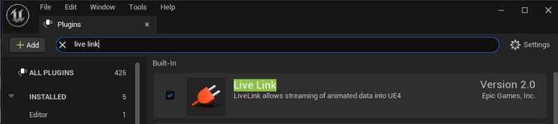
Go to Edit → Plugins and enable the two required plugins:
OptiTrack - Live Link plugin, located under the Installed group. This is the plugin downloaded in the previous step.
Unreal Engine's built-in Live Link plugin.
Search for Live Link on the plugins window to find these and other Live Link related plugins.
Allow Unreal Engine to restart, then close the plugin window when the project reloads.
Show Content
To show the OptiTrack plugins folder in the Content Browser, click the Settings button in the Browser's top right corner and check the boxes to Show Engine Content and Show Plugin Content.
In the NatNet section, select Enable to begin streaming.
Select the Local Interface. Use Loopback if streaming to the same computer, otherwise select the IP address for the network where the client application resides.
Set the Bone Naming Convention to UnrealEngine.
Set the Up Axis to Y-Axis. The plugin will bring the data in with a Y-Forward orientation.
Please see the Data Streaming page for more details on all settings available for streaming.
In Unreal Engine, open Live Link Hub from the Tools menu on the toolbar, if it's not open already. Under Virtual Production, select Live Link Hub.
Select OptiTrack Source, check Connect Automatically, or enter the IP address for the Motive PC in the Server Address field, the IP address for the Unreal PC in the Client Address field. Enter 127.0.0.1 in both fields if running both on the same PC. Click create.
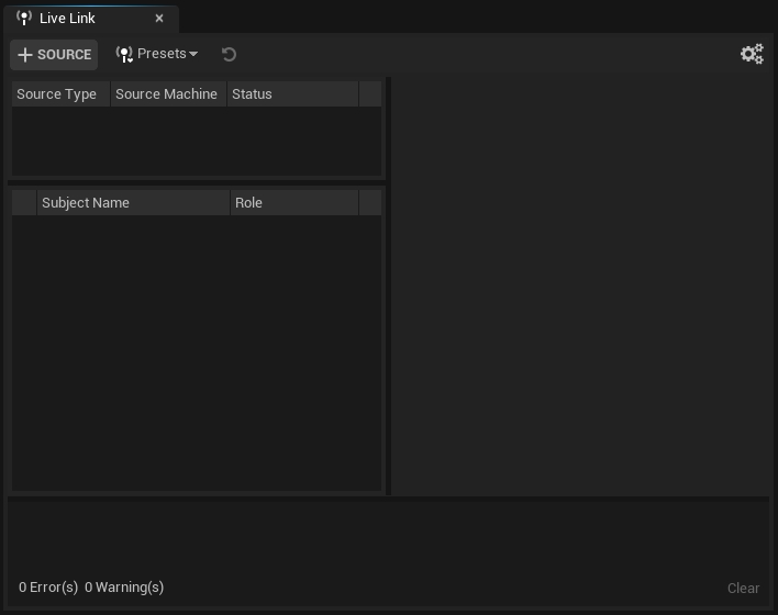
Live Link will display information about the connection, including a list of assets streaming from Motive:
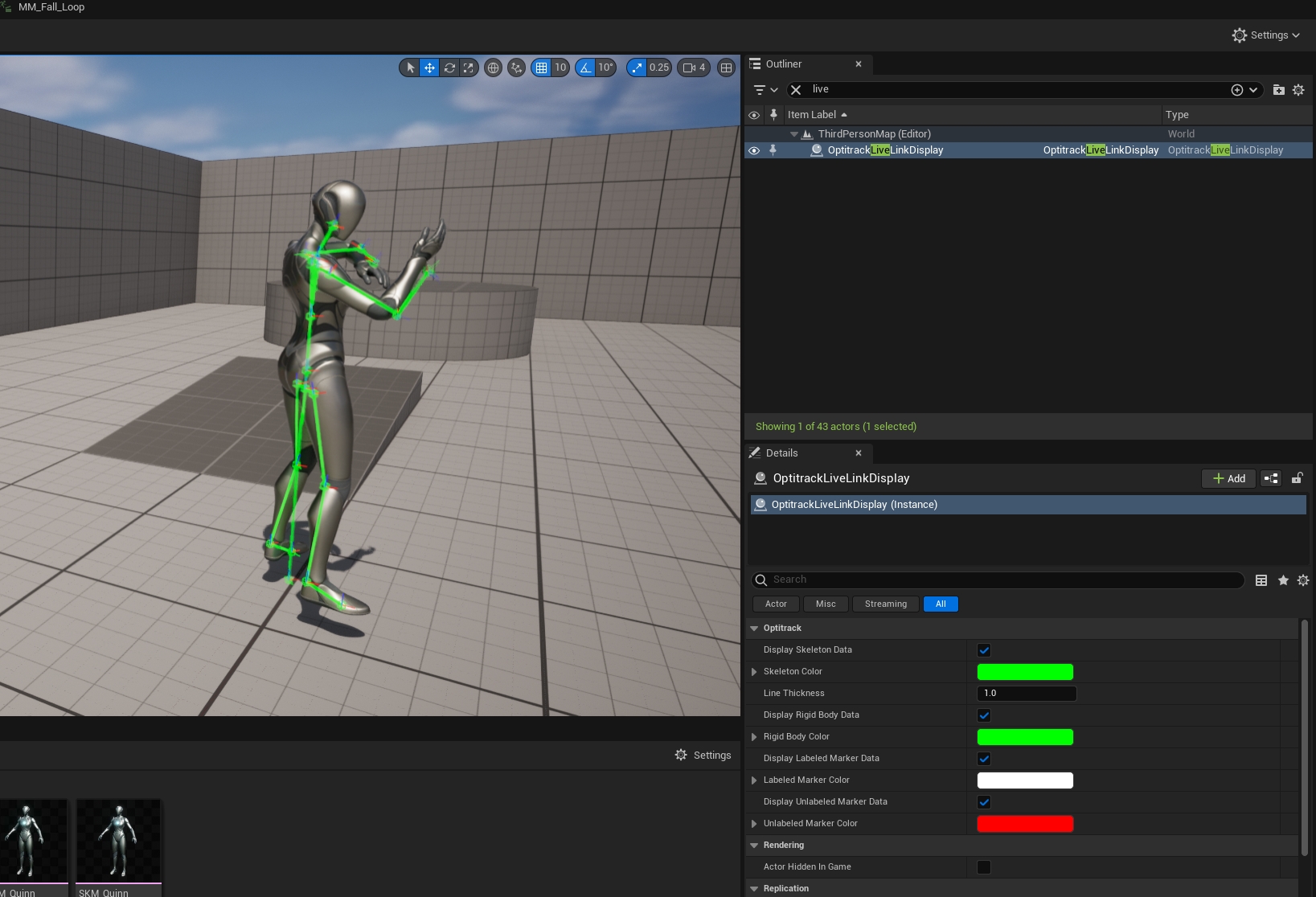
The OptiTrack Live Link Display provides validation that the data is streaming in correctly from Motive. In the Unreal Engine Outliner pane, all assets in the Motive volume should nest under the OptiTrack Live Link Display.
Play the Take file when working with recorded data to see the Live Link assets in the Viewport. Once the assets are available, you can pause playback and the assets will still be displayed.
Once you have validated the Live Link connection, we recommend turning off Live Link asset visibility to improve performance as you work through the rest of the pipeline.
Select OptitrackLiveLinkDisplay in the Outliner panel.
The properties for the OptitrackLiveLinkDisplay will populate in the Details pane.
In the Assets section, uncheck Display Assets.
Turn the Display Assets setting on or off as needed throughout the workflow.
Retargeting is the process of applying an existing animation model to a character, at the correct scale.
In this section, we'll demonstrate the retargeting workflow using skeleton data streaming from Motive and retarget it to a MetaHuman in Unreal Engine in real-time. For each MetaHuman, we'll create the following in Unreal Engine:
A Retargeter to map the Motive Animation data to the correct Skeletal Meshes in Unreal.
An Animation Blueprint for the Motive Avatar.
An Animation Blueprint for the MetaHuman.
A Blueprint for a MetaHuman character.
For more information and tutorials about working with MetaHumans in Unreal Engine, please visit Epic Games' MetaHuman community.
This workflow is fine-tuned specifically for MetaHumans, but it can also be used for other characters with unique custom skeletons.
MetaHuman joints use a Y-Forward axis, and the plugin brings the data in using this orientation.
Prior versions of the plugin used an X-Forward axis for the skeletal mesh, with adjustments made to the linked asset in Unreal Engine. To work with legacy assets configured for an X-Forward axis:
From the LiveLink tab, select OptiTrack to display the LiveLink properties.
In the Coordinates section, uncheck Animate Y-Forward.
We'll start the workflow by adding the MetaHuman to the project. This will create a folder structure in the project to consolidate the content related to each individual MetaHuman. We'll use these folders to save the Retargeter and the two Animation Blueprints we need to complete the retarget.
To add a new MetaHuman to your project:
Select either a new MetaHuman from a preset to download or browse the local collection for any previously downloaded MetaHumans.
Once the MetaHuman is downloaded, a green arrow will appear in the upper left corner of the profile picture. Click the blue arrow in the upper right corner to add the MetaHuman to your project.
The DNA Import Options window will open. Select the appropriate Skeletal Mesh for the new MetaHuman. All OptiTrack skeletal meshes end with _Opti, making them easily searchable. Gender-specific meshes include an "F" or an "M" in the name. Legacy meshes using an X-Forward axis include "Xforward."
The Content Browser will have a new MetaHumans folder within the Content folder. Each MetaHuman has their own folder, which contains their Blueprint and all the content needed to render them.
We recommend using a copy of the MetaHuman when setting up the retarget. This allows you to take the data that comes from the MetaHuman in the retarget during production and add it to the original MetaHuman later in post-production.
To create a copy, right-click the Blueprint and select Duplicate, or use the keyboard shortcut Ctrl + D.
We suggest using a simple convention such as BP_<MetaHumanName>_Retarget for all copies.
Now that the file structure for the MetaHumans is setup, we can create the Retargeter and the two Animation Blueprints. We'll update the MetaHuman Blueprint once these are done.
In the Content Browser, browse to and open the folder for the MetaHuman.
Right-click the Content Browser and select Animation -> Retargeting -> IK retargeter.
Name the retargeter. We recommend a name such as IKR_Motive_to_Meta.
Open the newly created retargeter. In the Details pane, update the Source and Target values as follows:
Source IKRig Asset: IK_MotiveAvatar_Opti
Source Preview Mesh:
Female avatars: SKM_F_MotiveAvatar_Opti
Male avatars: SKM_M_MotiveAvatar_Opti
Target IKRig Asset: IK_metahuman
Target Preview Mesh:
Female avatars: f_med_nrw_body
Male avatars: m_med_nrw_body
The Preview Mesh fields will auto-complete once the IKRig Asset is selected.
The Viewport will show that the two skeletons are not properly aligned. This occurs because the skeletons are in different poses.
Click the Running Retargeter button in the upper left corner to stop the retargeter and switch to edit mode. The button will update to Editing Retarget Pose.
The retarget will now display correctly in the Viewport.
Right-click the Content Browser and select Animation -> Animation Blueprint.
In the Create Animation Blueprint Search bar, type Opti, then select the SK_MotiveAvatar_Opti skeleton. Give the newly created Animation Blueprint a name, such as ABP_MotiveAvatar.
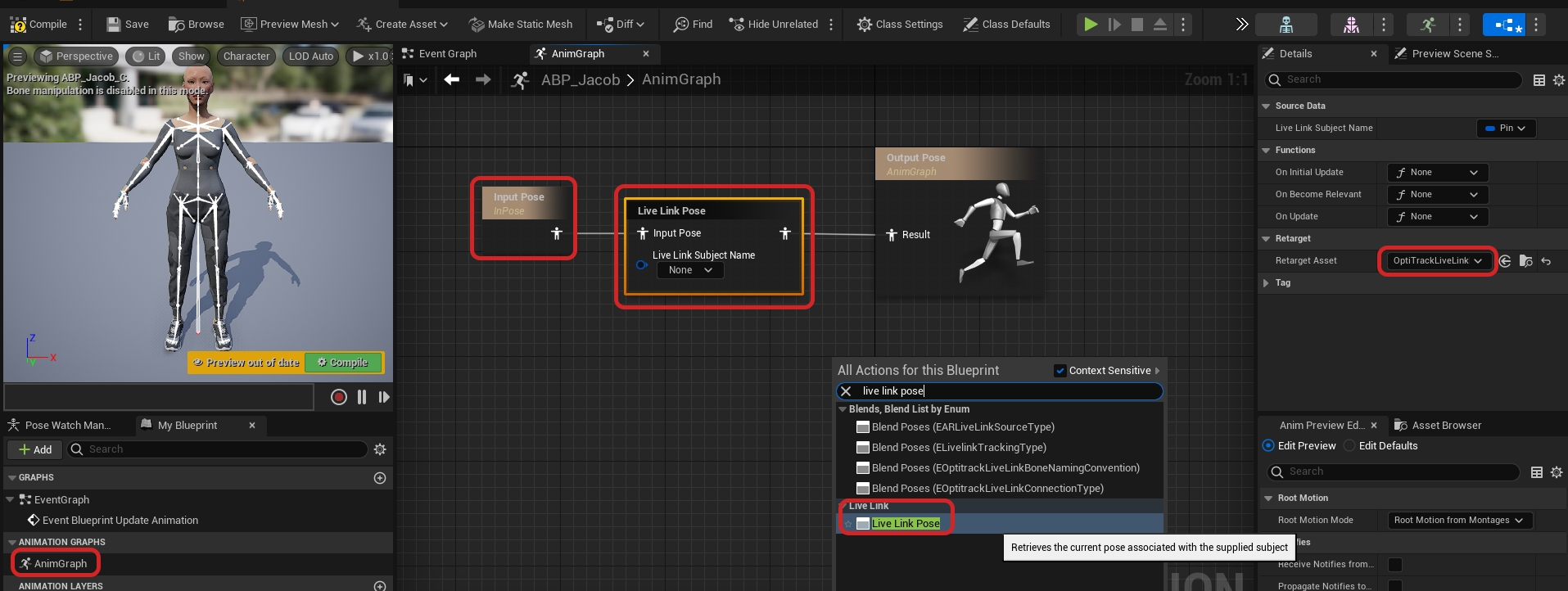
Double-click the new Animation Blueprint to open the AnimGraph window.
Right-click in the graph area and type Live Link Pose in the Search field, then select the node that appears.
In the Live Link Pose node, use the dropdown list under Live Link Subject Name to select the actor whose skeleton will be used for the Motive avatar.
To connect the two nodes, click the Result icon in the Output Pose and drag it to the corresponding icon on the Live Link Pose.
Click the Compile button, then Save. The Compile button will update as all changes are incorporated:
Right-click the Content Browser and select Animation -> Animation Blueprint.
On the Create Animation Blueprint window, select the metahuman_base_skel skeleton.
We suggest a naming convention such as ABP_<MetaHumanName>_Meta. Name, then open the newly created animation blueprint.
Right click the AnimGraph. From the list of All Actions, search for and select Retarget Pose From Mesh.
Select Retarget Pose from Mesh in the AnimGraph to display its properties in the Details pane.
Find IKRetargeter Asset in the Settings section.
Drag the Output Pose Result icon to the corresponding icon on the Retarget Pose From Mesh node to link the two.
Click the Compile button, then save.
Open the MetaHuman Blueprint created in a prior step.
Click the Viewport tab to see the MetaHuman character.
Name the new mesh something distinct, such as OptiTrackSkeletalMesh.
Drag the body component of the MetaHuman under the new skeletal mesh.
The Components should now look like this:
Next, add the Live Link Skeletal Animation component. This will allow playback to start once the animation blueprint is attached.
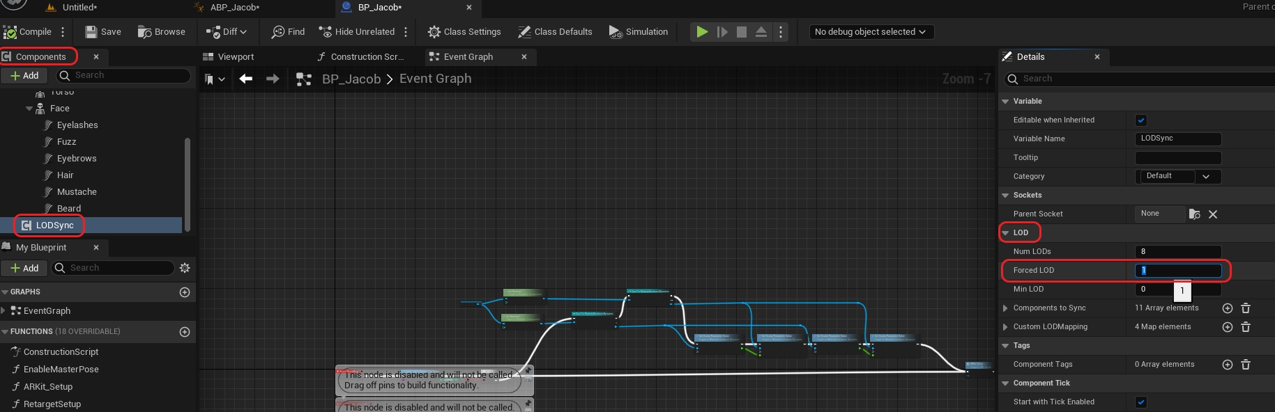
To improve performance while streaming to MetaHumans, click the LODSync component. In the Details pane, go to LOD -> Forced LOD and change the setting to 1.
Click Compile to update the Blueprint, then save.
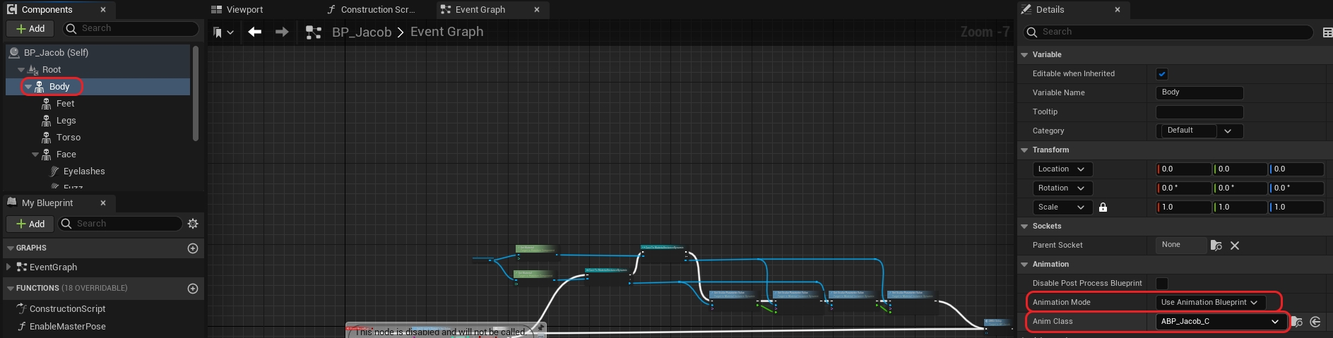
In the Components pane, select the OptiTrack skeletal mesh created previously.
In the Details pane, go to Animation -> Anim Class.
Use the drop-down to search for and select the Motive Avatar Animation Blueprint created earlier.
With the OptiTrack skeletal mesh still selected, go to Mesh -> Skeletal Mesh Asset.
Type Opti in the dropdown's search bar to quickly find the applicable Motive Avatar. This should match the the Source Preview Mesh used in the IK Retargeter created earlier:
Female avatar: SKM_F_MotiveAvatar_Opti
Male avatar: SKM_M_MotiveAvatar_Opti
In the Components pane, select the skeletal mesh for the MetaHuman. This is the Body previously moved to nest directly below the OptiTrack Skeletal mesh.
In the Details pane, go to Animation -> Anim Class.
Use the drop-down to search for and select the MetaHuman Animation Blueprint created earlier.
With the MetaHuman (body) skeletal mesh still selected, go to Mesh -> Skeletal Mesh Asset.
Select the same mesh used in the Target Preview Mesh in the IK Retargeter created earlier:
Female avatar: f_med_nrw_body
Male avatar: m_med_nrw_body
Animation should now be playing in the viewport of the MetaHuman blueprint.
Disregard any visual issues with the animation in this view. They will not appear in the environment when you add the MetaHuman to your scene.
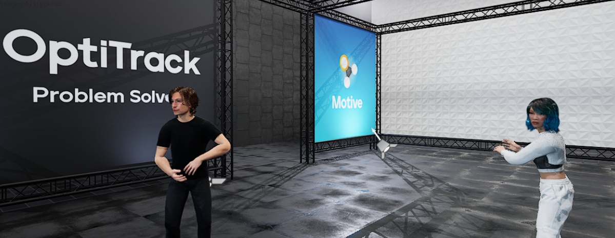
Now that the MetaHuman blueprint is configured correctly, drag it from the Content Browser into the scene.
In the Outliner pane, drag the newly added blueprint to the OptiTrackLiveLinkDisplay component created earlier. The mouse tip will display the drop location with a green checkmark as you drag the component, to show exactly where it will nest when the mouse is released.
Once the MetaHuman is nested under the OptiTrackLiveLinkDisplay, its location coordinates will update to reflect the OptiTrack global origin.
If you previously disabled the display of assets after setting up the OptiTrack Live Link Display, re-enable the display now to validate that the retarget is running correctly.
The MetaHuman may not be animating exactly as intended. At this point, the rest of retargeting is much more of a trial-by-error artistic process.
We achieved the best standard results using the following settings for all the Hand and Foot Goals, however, we recommend testing other values and changing other fields to get the best results for your project:
FK
Rotation Mode: One to One
Translation Mode: Absolute
IK
Blend to Source: 1
Prior versions of the plugin used an X-Forward axis for the skeletal mesh, with adjustments made to the linked asset in Unreal Engine. To work with legacy assets configured for an X-Forward axis, uncheck the box ...
This page provides instructions on how to configure VCS inputs in Unreal Engine. The basic configuration is similar to configuring any other input triggers in Unreal Engine. Please note that only one VCS controller can be connected and configured due to some limitations. Having two controllers connected at the same time is not supported.
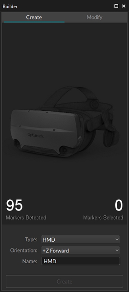
Create a Rigid Body from your tracking controller’s markers using the Builder pane or by selecting the markers and using the keyboard hotkey CTRL + T. You'll want to orient the controller along the +Z axis during creation to define the 'neutral' or 'zero' orientation.
In Motive, configure the data streaming settings. Use the Data Streaming pane to configure streamed packets. Make sure Rigid Body data is streamed out in order to use VCS.
Start up a project in Unreal Engine (UE).
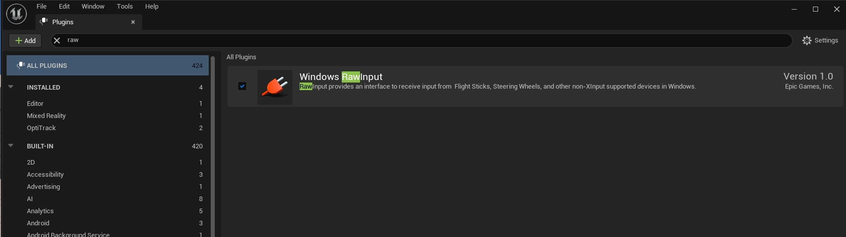
Go to Edit tab → Plugins to open the plugins panel. Enable the Windows RawInput plugin under the Input Devices group.
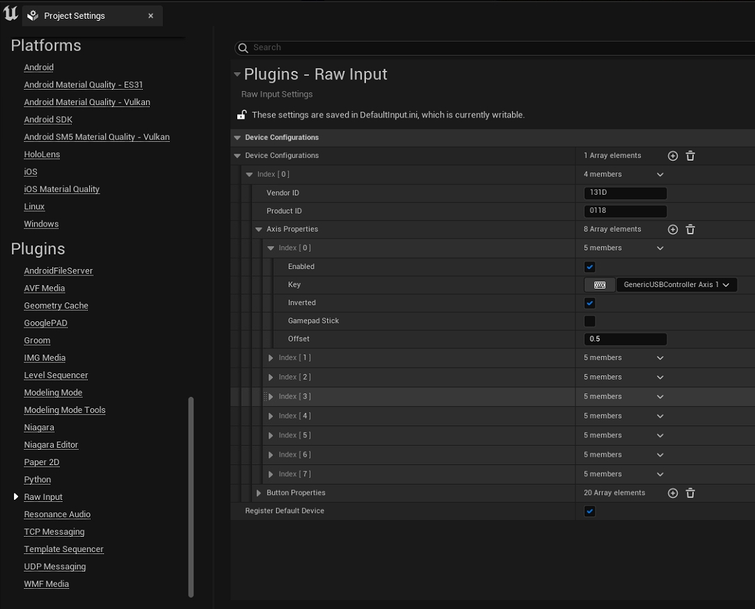
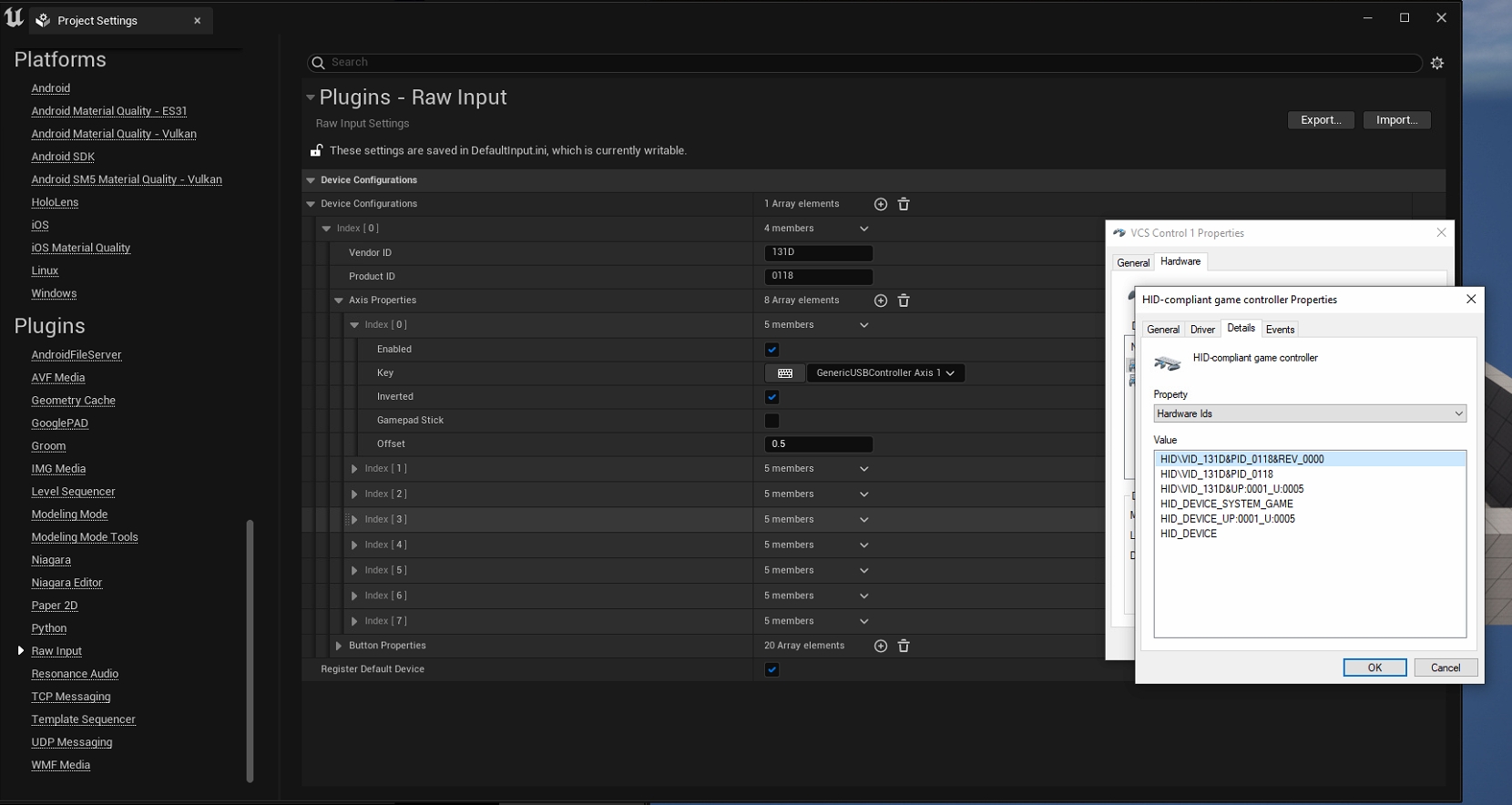
In Edit tab → Project Settings, scroll to the bottom on the left side panel until you see Raw Input under the plugins group. Here you will let UE project know which input devices to use.
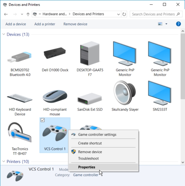
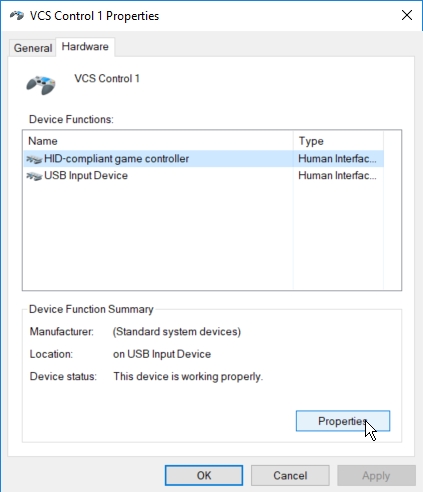
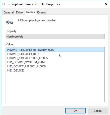
To find these IDs, you will need to look at the windows device properties. Go to Windows Control Panel -> Devices and Printers. Then right-click on the VCS controllers to access its properties. In the properties, go to the Hardware tab and click properties for “HID-compliant game controller”.
Once you access the controller properties, go to the details tab. Select Hardware ID in the drop-down menu and the hardware ID (HID) and product ID (PID) will be shown under the highlighted section.
Under the project settings panel Raw Input plugin properties, input both the vendor ID (Hardware ID) and the product ID (PID) that was found under the controller properties.
Register the Input Buttons
Now the project has the IDs to look for the controllers, next step is to setup and register the input buttons. To do so, you will play the project scene, and trigger on the buttons to register them.
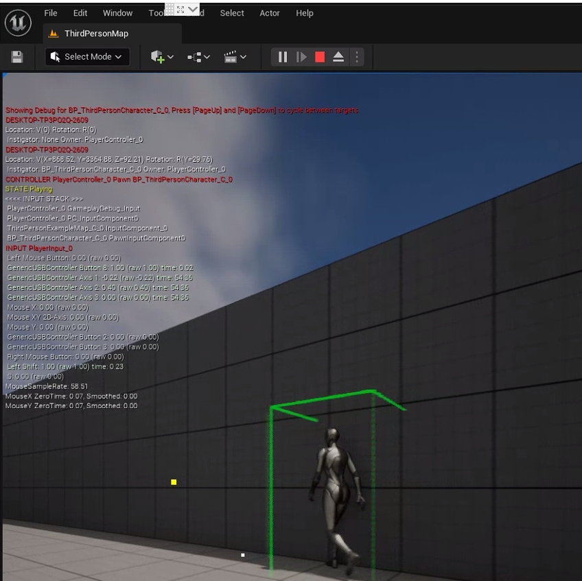
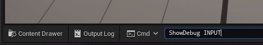
In UE, hit Play and press (~) to access the console. In the console, input command ShowDebug INPUT". This will list out all of the input actions on the left side of the viewport.
Use all of the keys on the controller to register the inputs; total three axis and seven buttons. Please note that these keys may not exactly match the keys on your controller.
Axis 1: Joystick left/right
Axis 2: Joystick up/down
Axis 3: Nob rotate
Button 1: Blue
Button 2: Black
Button 3: White
Button 4: Red
Button 6: Joystick click
Button 7: Nob click
Map the Registered Inputs
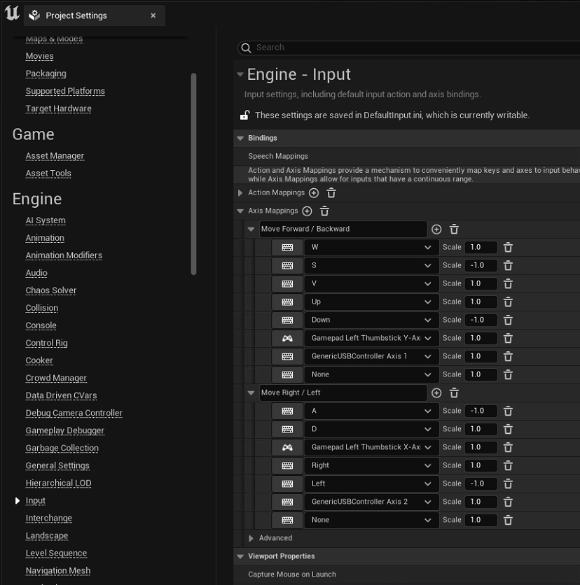
Now that the buttons have been registered, next step is to map the keys. They will be mapped under Edit → Project Settings → Inputs. Choose either the Axis mapping or the action mapping to map the controls to desired actions.
Now that all of the buttons are set up, use them to control the VCS in UE.
This page provides instructions on how to use the OptiTrack Unreal Engine Live Link plugin. The plugin communicates with Unreal's built-in Live Link system by providing a Live Link source for receiving tracking data streamed from Motive. This plugin can be used for controlling cameras and objects in virtual production applications. When needed, the OptiTrack Unreal Engine Plugin can also be alongside this plugin. For a specific guide to InCamera VFX (i.e. LED Wall Virtual Production) please see this wiki page Unreal Engine: OptiTrack InCamera VFX.
1. [Motive] Setup Rigid Body streaming in Motive.
Get Motive streaming with at least one Rigid Body or Skeleton asset. Make sure the Streaming settings are configured correctly, and the asset is active under the Assets pane.
2. [UE] Install the OptiTrack plugins in Unreal Engine (UE).
You can install the OptiTrack Unreal Engine plugin by putting the plugin files into one of the following directories:
A global engine plugin can be placed in C:\Program Files\Epic Games\ [Engine Version]\ Engine\ Plugins\ Marketplace
A project-specific plugin can be placed in [Project Directory]\Plugins
3. [UE] Enable the plugins in UE project.
Go to Edit → Plugins and enable two of the required plugins. First one is the OptiTrack - Live Link plugin under Installed group, and the second one is the built-in Live Link plugin under Built-In group.
4. [UE] Open the LiveLink pane
Open the LiveLink pane from Window → Virtual Production → Live Link in the toolbar.
5. [UE] Configure and create a new OptiTrack source
In the LiveLink pane under Source options, go to the OptiTrack Source menu and configure the proper connection settings and click Create. Please make sure to use matching network settings configured from the Streaming pane in Motive.
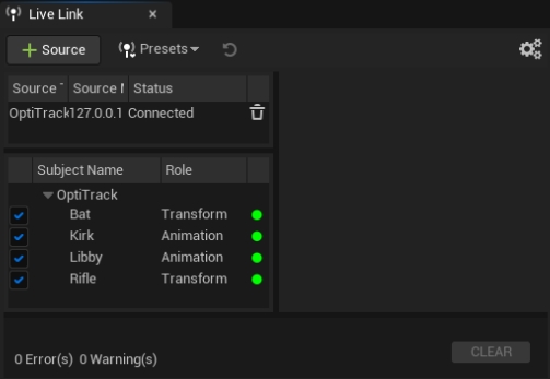
6. [UE] Check the Connection.
If the streaming settings are correct and the connection to Motive server is successful, then the plugin will list out all of the detected assets. They should have green dots next to them indicating that the corresponding asset has been created and is receiving data. If the dots are yellow, then it means that the client has stopped receiving data. In this case, check if Motive is still tracking or if there is a connection error.
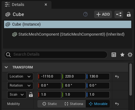
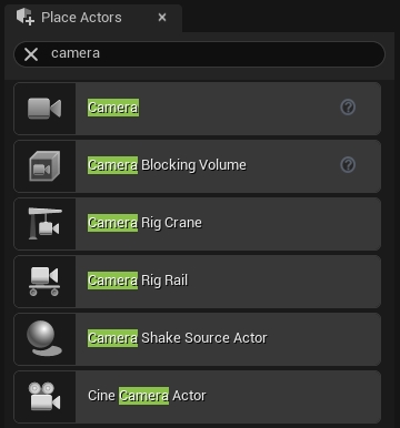
1. Add the camera object or static mesh object that you wish to move
Add a camera actor from the Place Actors pane or a static mesh from the project into your scene. For the static meshes, make sure their Mobility setting is set to Movable under the Transform properties.
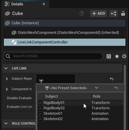
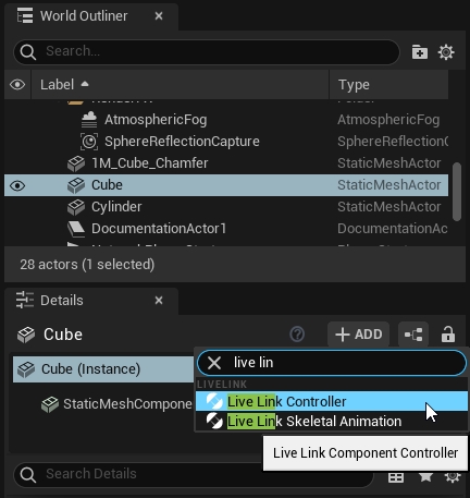
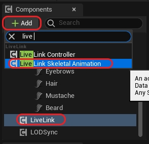
2. Add a LiveLinkController Component
Select an actor you want to animate. In the Details tab select your "actor" (Instance). In the search bar, type in Live Link. Then click on the Live Link Controller from the populated list.
3. Select the target Rigid Body
Under the Live Link properties in the Details tab click in the Subject Representation box and select the target Rigid Body.
4. Check
Once the target Rigid Body is selected, each object with the Live Link Controller component attached and configured will be animated in the scene.
When the camera system is synchronized to another master sync device and a timecode signal is feeding into eSync 2, then the received timecode can be used in UE project through the plugin.
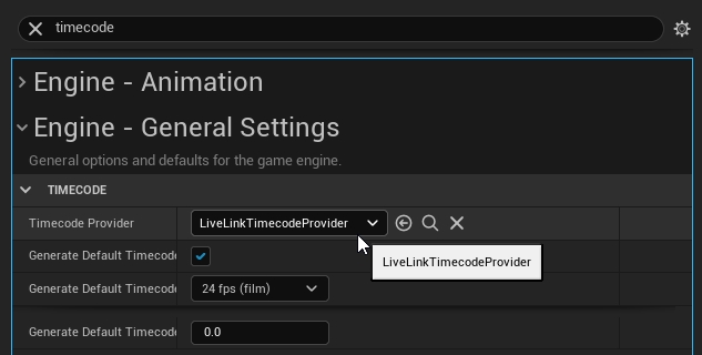
1. Set Timecode Provider under project settings
From Edit → Project Settings, search timecode and under Engine - General settings, you should find settings for the timecode. Here, set the the Timecode Provider to LiveLinkTimeCodeProvider.
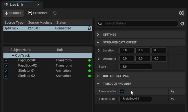
2. Set OptiTrack source in the Live Link pane as the Timecode Provider
Open the Live Link pane, and select the OptiTrack subject that we created when first setting up the plugin connection. Then, under its properties, check the Timecode Provider box.
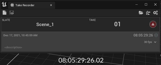
3. Check
The timecode from Motive should now be seen in the Take Recorder pane. Take Recorder pane can be found under Window → Cinematics → Take Recorder in the toolbar.
1. Create a new Animation Blueprint
Right click the mesh you would like to use and select "Create > Anim Blueprint"
2. Name and Open the Animation Blueprint
Name the animation blueprint something appropriate, then double click it to open the blueprint.
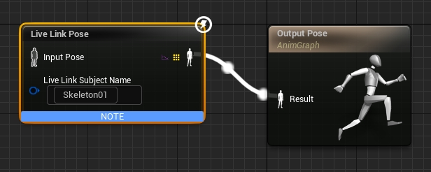
3. Hook up your Blueprint
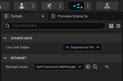
Create a "Live Link Pose" component and connect it to the "Output Pose". Assign the "Live Link Subject Name" to the Skeleton that you would like to use.
Change the "Retarget Asset" property in the Details pane of the blueprint editor to "OptiTrackLiveLinkRetarget"
4. Getting the Skeleton to Animate
To animate the Skeleton in real time click the Animation Blueprint from earlier. In the Details pane under the skelteonLive Link Skeleton Animation". After you add that component the mesh should start animating.
To animate the Skeleton in a game, just press the play button. Adding the "Live Link Skeleton Animation" object is not necessary to animate in play mode.
5. OptiTrack Live Link Display
In order to see the debug skeleton overlay from Motive, you can enable the OptiTrack Live Link Display. From the Quick Add dropdown from the toolbar, you can select OptiTrack Live Link Display. This will appear in the Outliner tab and you can change any settings in its Details tab as needed.
Debugging Note
If the retargeting doesn't match the mesh correctly, then you can create a new OptiTrackLiveLinkRetarget blueprint from scratch and modify the bone mapping names.
Animating a MetaHuman follows basically the same steps as another Skeleton, but requires hooking into the Skeleton at a very specific location. For more information about MetaHuman setup outside of our scope, please visit Epic Games's website.
First, you'll want to verify that the Quixel Bridge plugin is installed with Unreal Engine 5. You can install the Quixel Bridge plugin from the Epic Games Launcher by clicking Unreal Engine then the Library Tab.
You'll also wan to make sure that the Quixel Bridge plugin is enabled. To do this go to Edit > Plugins > Editor and click the check box. You may have to restart Unreal after enabling this plugin.
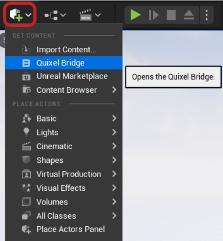
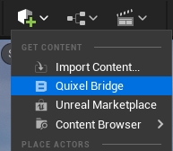
Navigate to the Cube + icon in the top toolbar, select the dropdown and choose Quixel Bridge.
From here, log into your account and select the MetaHuman you want to download/ add to your project.
In your newly created MetaHuman folder (Note: The folder will be labeled whatever your MetaHuman name is), in the Content Browser, create an animation blueprint by right clicking and navigating to Animation> Animation Blueprint.
For the skeleton asset, simply choose the metahuman_base_skel. There is no need to choose anything different for the parent class, keep it as AnimInstance.
Click Create and name it, “ABP_ Metahuman Name”
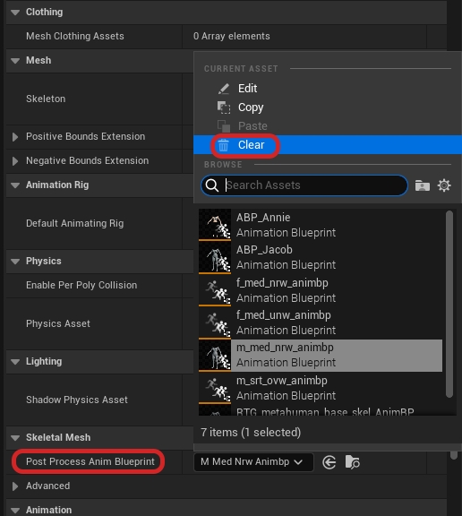
Each MetaHuman will have a “Body” mesh attached to the MetaHuman blueprint. This mesh will have a post-processing animation blueprint automatically attached to it when you import it into your project. We want to remove this from the mesh because it can cause crashing errors if they are used improperly.
Now in the mesh, scroll down to the Skeletal Mesh section and clear the “Post Process Anim Blueprint”.
With this done, you can now use multiple MetaHumans in your project while all of them are using the same skeleton.
Removing this Post Process Anim Blueprint disabled any way of the mesh itself receiving animations.
Now we will drive all the animation in the animation blueprint we made earlier.
You can also simply choose the animation blueprint that you made as well. It may cause multiple calls to the blueprint and in multiple areas, so be cautious.
Open the animation blueprint that we made in step 2.
You should now see the Animation Graph, if you don’t, navigate to the left in the Animation Graphs and click on “AnimGraph”. In the AnimGraph, right click and type “Live Link Pose”.
Now attach it to the OutPut Pose node.
You can add an input pose if you’d like to keep your blueprint free of any compile notes or errors.
While you have the “Live Link Pose” node selected, navigate to the Details panel and under retarget, select Retarget Asset > OptiTrackLiveLink.
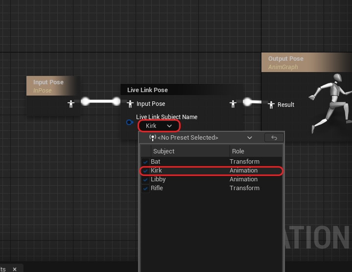
Now to choose an actor.
Make sure you have added a live link source streaming over from Motive.
Choose an actor for the selected dropdown.
You can select a different actor per AnimBlueprint, as long as you have the proper Post Process Blueprint Animation settings. Referenced in step 3.
Click Compile and Save.
Next, navigate to your MetaHuman blueprint and open it.
In the “Components” section on the left, scroll down and select LODSync.
Now on the right go to LOD > Forced LOD and choose any LOD that works for your use-case.
Do not use –1 as the Forced LOD as this will crash Unreal.
Go back to the Components panel and click on Body.
On the right in the Details panel, go to Animation> Animation Mode> Use Animation Blueprint.
In the Anim Class choose the MetaHuman AnimBP that you created earlier.
Lastly in the Components panel, click the '+ Add' button and type in ”Live Link Skeletal Animation” and then click Compile.
If you go to your main Map, you can click and drag your MetaHuman in the scene to watch them animate in Realtime.
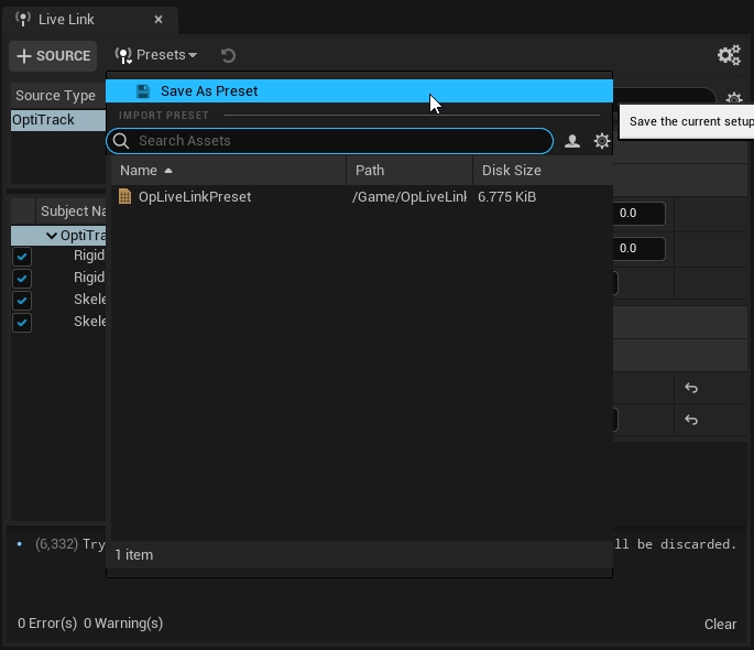
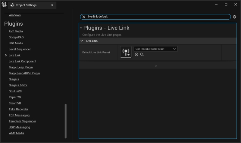
For testing the project in standalone game mode, or when developing an nDislay application, the Live Link plugin settings must be saved out and selected as the default preset to be loaded onto the project. If this is not done, the configured settings may not get applied. After configuring the LiveLink plugin settings, save out the preset from the Live Link pane first. Then, open the Project Settings and find Live Link section in the sidebar. Here, you can select the default Live Link preset to load onto the project, as shown in the screenshot below. Once the preset is properly saved and loaded, the corresponding plugin settings will be applied to the standalone game mode.
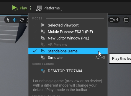
If all the configuration is correct, the actors will get animated in the newly opened game window when playing the project in the standalone game mode.
Another path to get data into Unreal Engine is to stream data from Motive -> MotionBuilder (using the OptiTrack MotionBuilder Plugin) -> Unreal Engine (using the Live Link plugin for MotionBuilder). This has the benefit of using the Human IK (HIK) retargeting system in MotionBuilder, which will scale characters of very different sizes/dimensions better than the base Live Link plugin. More information can be found by consulting Unreal Engine's Live Link to MotionBuilder documentation.
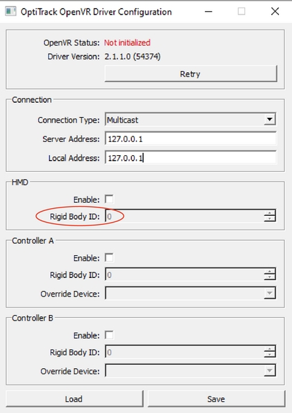
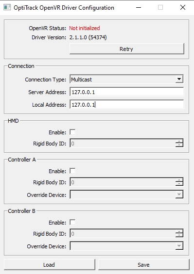
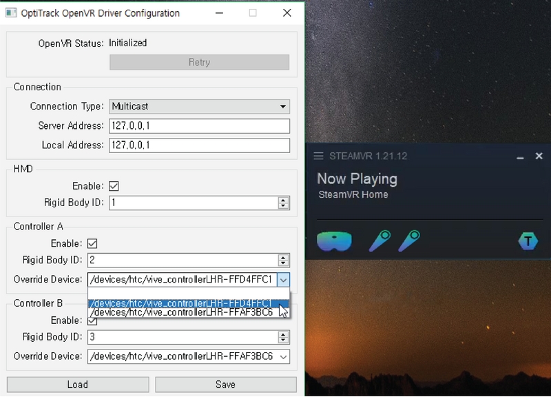
This page provides instructions on setting up the OptiTrack OpenVR driver for integrating OptiTrack system with Vive HMDs within SteamVR applications; including Unreal Engine and Unity.
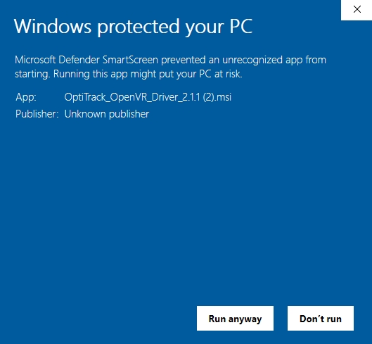
For integrating Vive HMDs, the OptiTrack OpenVR Driver must be used. This driver lets you track the head-mounted display (HMD) and the VR controllers using OptiTrack motion capture system and stream the tracking data from Motive directly into SteamVR. In other words, this will basically override the tracking from the lighthouse stations. The plugin ships as an installer package (MSI) which will set up the driver along with a utility tool for configuring client streaming settings. Once integrated, the streamed tracking data can be used in any application platform that utilizes SteamVR. For tracking of objects other than the HMDs, please read through the OptiTrack Unreal Engine Plugin page for details.
Supported Systems
Vive
Vive Pro 1/2
Valve Index
HP Reverb G2
When developing for SteamVR applications using the OpenVR Driver to track the HMD in Unreal Engine 4, the OptiTrack - Streaming Client version 2.27 must be used and the OptiTrack - VR Latency Optimization version 2.27 plugin is suggested. The OptiTrack - VR Latency Optimization provides HMD render compensation that helps to minimize the latency in VR application.
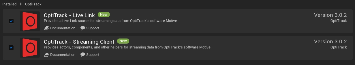
The latest plugins that support Unreal Engine 5 are OptiTrack - Live Link version 3.0 and OptiTrack - Streaming Client version 3.0.
First of all, setup and optimize the motion capture volume as explained in the Getting Started guide or the Hardware Setup documentation. If you plan to install any obstacles (e.g. walls) within the capture volume, make sure they are non-reflective, and place and orient the cameras so that every corner is thoroughly captured by multiple cameras.
General Setup Steps
Attach the markers on the HMD
Create a Rigid Body asset
Calibrate the Pivot Point of the Rigid Body
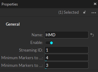
Configure the Rigid Body settings in Motive
For the camera system to track the HMD, a set of markers must be attached to the HMD. You can either use the active markers (Active HMD clip or Active Tags) or the passive markers. Passive markers are retroreflective markers that reflect infrared light emitted from the IR LEDs on the camera. On the other hand, the active markers are LED markers that emit the IR light and has the intelligence to be uniquely identified.
In general, for most VR applications, using active markers is recommended for better tracking stability and ease of use. Active markers also have advantages over passive markers when tracking a large number of objects. For applications that are sensitive to the accuracy of the tracking data, using passive marker may have more benefits. To get more help with finding the best solution for your tracking application, please contact us.
When using the active markers, you can conveniently put a set of 8 markers onto the HMD by using the HMD Clip, or you can attach the markers from the Tag manually onto the HMD using adhesives and marker posts.
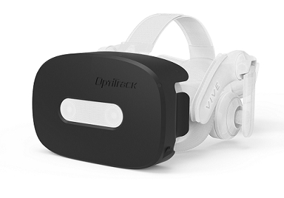
Active HMD Clip
Active HMD Clip is an HMD enclosure with a total of 8 active markers embedded for tracking. At the time of writing, there are active HMD clips for Vive Pro / Valve Index HMDs available on the webstore. The clips can be mounted easily by pushing it onto the HMD until the latches click, and you can detach it by gently lifting the three latches located at the top, left, and right side of the clip.
Once the clip has been mounted, next step is to import the provided Rigid Body asset into Motive and refine the definition to get the calibrated pivot point position and orientation, which will be explained on the next section.
Marker Types
You can either use the passive retro-reflective type markers or the active LED markers to track the HMD. Passive markers are retroreflective markers that reflect infrared light emitted from the IR LEDs on the camera. On the other hand, the active markers are LED markers that emit the IR light which gets uniquely identified in Motive. Either type of marker can be used to track HMDs. Using active marker is recommended especially for applications that involve tracking of multiple HMDs in the scene.
Marker Placement
Make sure the markers are attached securely and do not move. If the markers happen to move even slightly after a Rigid Body is defined, it will negatively affect the tracking and the Rigid Body definition may need to be updated.
Avoid placing multiple markers in close vicinity as they may overlap in the camera view in certain orientations.
Using marker posts to extend out the markers is recommended to improve marker visibility from more angles.
If you are using the active markers, there is an extra USB port on the HMD that you could draw the power from.
Please read through the Rigid Body Tracking page for additional information on the marker placement on a Rigid Body.
This feature can be used only with HMDs that have the OptiTrack Active HMD clips mounted.
For using OptiTrack system for VR applications, it is important that the pivot point of HMD Rigid Body gets placed at the appropriate location, which is at the root of the nose in between the eyes. When using the HMD clips, you can utilize the HMD creation tools in the Builder pane to have Motive estimate this spot and place the pivot point accordingly. It utilizes known marker configurations on the clip to precisely positions the pivot point and sets the desired orientation.
HMDs with passive markers can utilize the External Pivot Alignment tool to calibrate the pivot point.
Steps
First, make sure Motive is configured for tracking active markers.
Open the Builder pane under View tab and click Rigid Bodies.
Under the Type drop-down menu, select HMD. This will bring up the options for defining an HMD Rigid Body.
If the selected marker matches one of the Active clips, it will indicate which type of Active Clip is being used.
Under the Orientation drop-down menu, select the desired orientation of the HMD. The orientation used for streaming to Unity is +Z forward and Unreal Engine is +X forward, or you can also specify the expected orientation axis on the client plugin side.
Hold the HMD at the center of the tracking volume where all of the active markers are tracked well.
Select the 8 active markers in the 3D viewport.
Click Create. An HMD Rigid Body will be created from the selected markers and it will initiate the calibration process.
During calibration, slowly rotate the HMD to collect data samples in different orientations.
Once all necessary samples are collected, the calibrated HMD Rigid Body will be created.
SteamVR Required: The VR driver streams tracking data through SteamVR. Please make sure SteamVR is installed on the computer before setting up the driver.
Download the OpenVR driver from the downloads page. Once downloaded, launch the installer and follow the prompts to set up the driver. On the last window, make sure to select Launch Configuration Utility before clicking Finish. This will open the Configuration options to setup your HMD with Motive.
You may receive a warning window prior to the installation wizard. To circumvent this, select More info and then Run Anyway.
Once the driver has been successfully installed, launch the configuration utility software (C:\Program Files\OptiTrack\OpenVR Driver\ConfigUtil). Using this tool, you can load and check existing configurations and make changes to the settings as needed. To import current settings, click Load and to save out the changes, click Save.
Please make sure you are running this tool with admin privileges; if not, it might not be able to modify the settings properly. If the configuration software detects a running instance of SteamVR through OpenVR, it will be indicated as Initialized at the very top as shown in the image. Please note that when the settings get modified while SteamVR is running, the SteamVR must be restarted to apply the changes.
First, configure the connection settings so that the driver listens to the Motive server where the tracking data is streamed from. The server address must match the address where Motive is streaming the data to, and the local address must match the IP address of the computer on the network where the driver is installed.
In the HMD section, enable the HMD and input the Rigid Body ID of the HMD. The Rigid Body ID must match the Streaming ID property of the HMD Rigid Body definition in Motive.
Save the configurations by clicking on Save. This will modify the set of configurations in the steamvr.settings file in the steam installation directory and they will override the HMD tracking with the tracking data from Motive. If you already had an instance of OpenVR or SteamVR running, restart the application to apply the changes.
Configuration File
The configuration tool basically imports and modifies the contents in the steamvr.settings file (C:\Program Files (x86)\Steam\config\steamvr.settings). When needed, the driver related settings can be changed directly from this file also, but it will be easier to configure the settings using the provided configuration tool.
Confirm the setup
Launch SteamVR. If the driver is successfully set up, you should see a tracker icon added to the right of the HMD icon and the HMD will now be using the motion capture system instead of the base stations. Here, please make sure all of the lighthouse base stations are powered off.
VIVE controllers are a Beta feature and may not work for every device. Support for this particular feature is limited.
When needed, the Vive controllers can be configured as well. To do so, open the configuration utility tool while SteamVR is running. At the top of the configuration tool, it should indicate OpenVR status as Initialized and the controllers must be showing up in SteamVR. Then, in the controller sections, enable the controllers, specify the override device using the drop-down menu, and input the corresponding streaming ID of the controller Rigid Bodies in Motive. Once everything has been configured, save the changes and restart SteamVR. When the override is configured properly, SteamVR will have an additional tracker icon per each enabled controller.
Now that the driver is set up, the HMD tracking will be overridden by tracking data from the mocap camera system, and you can integrate HMDs into the game engine through their own VR integration.
First, make sure the streaming settings are configured in Motive for streaming out the data. For more information regarding streaming in Motive please visit our Streaming wiki page:
Enable must be set to toggled on.
Local interface must be set to the desired IP address to stream the tracking data from.
Streaming of Rigid Bodies must be set to True
For wireless streaming, use Unicast streaming type.
Once Motive is configured for streaming, launch SteamVR home to check the connection. If everything is setup correctly, you should be able to move around, or translate, within the scene freely. You may also need to check the ground plane to make sure it's well aligned.
If you experience any unexpected rotations in the view as you move your head, it could indicate that the HMD pivot point has not been calibrated properly. Please revisit the HMD Setup section and make sure the HMD Rigid Body pivot point is positioned and oriented at the expected pivot; which is at the root of nose with z-forward.
Make sure Unreal Engine is configured for SteamVR development. Please refer to the Unreal Engine's documentation for more information on developing for SteamVR.
This driver is designed for streaming of HMD and controller tracking data only. For streaming tracking data of other Rigid Body objects, you will need to use the corresponding plugins (UnrealEngine or Unity). In other words, the HMD tracking data will be streamed through the SteamVR using the driver you've installed, and all other tracking data will be streamed through the plugin.
Client Origin
When using the OpenVR driver for the HMD and the game engine plugins (UE/Unity) for other types of tracking data, including Rigid Body data, the client origin object must be located at the global origin without any rotations. In other words, the position must be set to (0,0,0) and the rotation must be set to (0,0,0) on the client origin. This is important because this will align the coordinate system from the (UE/Unity) plugin with the coordinate system in OpenVR pipeline
Notes for Unreal Engine Users
When using the Unreal Engine plugin, you will need to additionally create a custom pawn for properly aligning the coordinate systems between SteamVR and OptiTrack UE plugin:
Create an "OptTrack Client Origin" to the scene and set the relevant connection info. Refer to the OptiTrack Unreal Engine Plugin page for more information on setting up the client origin.
Create a new pawn. Right-click in Content Browser, and from the context menu, select Blueprint → Blueprint Class → Pawn.
Load created Blueprint in the editor and add a camera component.
(optional) Double-check that the “Lock to HMD” property is set to true under the camera component properties in the details pane.
Select the pawn and set the “Base Eye Height” property to 0 in the details pane.
Compile the pawn then add it to the scene.
Select the pawn and set the “Auto Possess Player” to “Player 0”.
The HMD should now be working for Levels built for VR.
To enable streaming in Motive, click the button to open the Applications Settings panel, then select the Streaming tab, or use the button in the right corner of the Control Deck to open the Streaming tab directly.
Click the button in Live Link Hub to add a new Live Link source.
Click the Quick Add button and start typing OptiTrack over the menu to activate the search function. Select the OptiTrack Live Link Display from the list of available options and drop it into the scene in the desired location.
Click the Quick Add button and select Quixel Bridge.
Click the Auto Align button and select Align all Bones to complete the alignment.
Click the button and select the IK retargeter created in the prior step.
In the Components panel, Click the Add button and select Skeletal Mesh.
To align the MetaHuman with the subject configured in the Motive Avatar Animation Blueprint, go to Details -> Transform and zero out the coordinates by clicking the button to the right of the values.
Open your MetaHuman blueprint by double-clicking it. In here, click the Body in the components section, and in the details, panel go to Mesh> Skeletal Mesh, then click to navigate to the mesh in the content browser. Open the mesh by double clicking on it.