Loading...
Loading...
Loading...
Loading...
Loading...
Loading...
Loading...
Loading...
Loading...
Loading...
Loading...
Loading...
Loading...
Loading...
Loading...
Loading...
Loading...
Loading...
Loading...
Loading...
Loading...
Loading...
Loading...
Loading...
Loading...
Loading...
Loading...
Loading...
Loading...
Loading...
Loading...
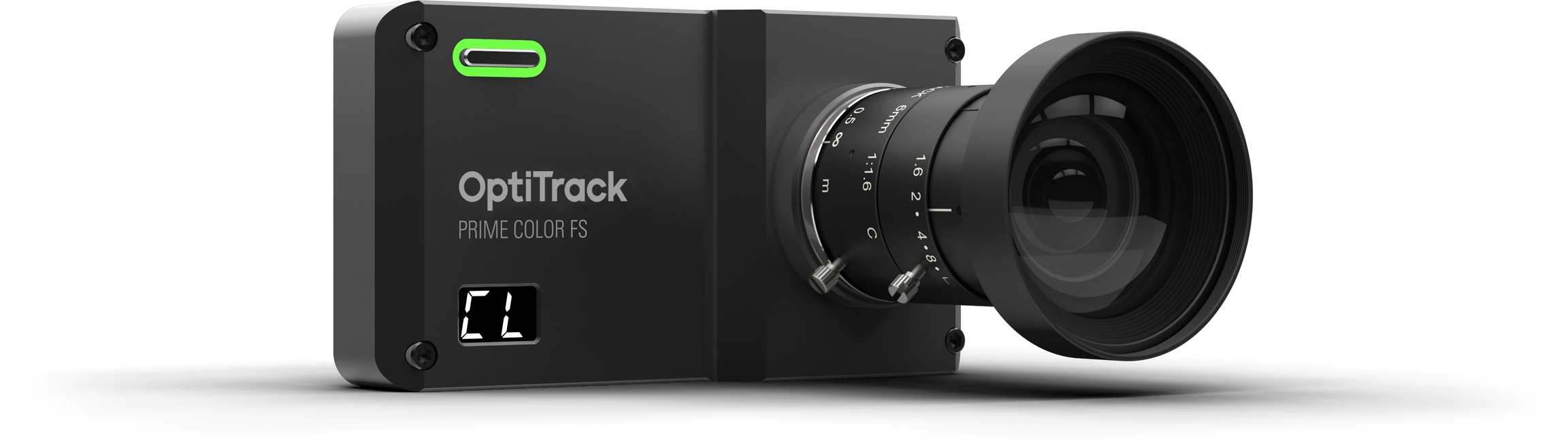
This page is for the general specifications of the Prime Color camera. For details on how to setup and use the Prime color, please refer to the Prime Color Setup page in this wiki.
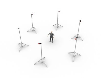
In optical motion capture systems, proper camera placement is very important in order to efficiently utilize the captured images from each camera. Before setting up the cameras, it is good idea to plan ahead and create a blueprint of the camera placement layout. This page highlights the key aspects and tips for efficient camera placements.
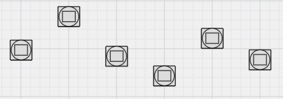
A well-arranged camera placement can significantly improve the tracking quality. When tracking markers, 3D coordinates are reconstructed from the 2D views seen by each camera in the system. More specifically, correlated 2D marker positions are triangulated to compute the 3D position of each marker. Thus, having multiple distinct vantages on the target volume is beneficial because it allows wider angles for the triangulation algorithm, which in turn improves the tracking quality. Accordingly, an efficient camera arrangement should have cameras distributed appropriately around the capture volume. By doing so, not only the tracking accuracy will be improved, but uncorrelated rays and marker occlusions will also be prevented. Depending on the type of tracking application, capture volume environment, and the size of a mocap system, proper camera placement layouts may vary.
An ideal camera placement varies depending on the capture application. In order to figure out the best placements for a specific application, a clear understanding of the fundamentals of optical motion capture is necessary.
To calculate 3D marker locations, tracked markers must be simultaneously captured by at least two synchronized cameras in the system. When not enough cameras are capturing the 2D positions, the 3D marker will not be present in the captured data. As a result, the collected marker trajectory will have gaps, and the accuracy of the capture will be reduced. Furthermore, extra effort and time will be required for post-processing the data. Thus, marker visibility throughout the capture is very important for tracking quality, and cameras need to be capturing at diverse vantages so that marker occlusions are minimized.
Depending on captured motion types and volume settings, the instructions for ideal camera arrangement vary. For applications that require tracking markers at low heights, it would be beneficial to have some cameras placed and aimed at low elevations. For applications tracking markers placed strictly on the front of the subject, cameras on the rear won't see those and as a result, become unnecessary. For large volume setups, installing cameras circumnavigating the volume at the highest elevation will maximize camera coverage and the capture volume size. For captures valuing extreme accuracy, it is better to place cameras close to the object so that cameras capture more pixels per marker and more accurately track small changes in their position.
Again, the optimal camera arrangement depends on the purpose and features of the capture application. Plan the camera placement specific to the capture application so that the capability of the provided system is fully utilized. Please contact us if you need consulting with figuring out the optimal camera arrangement.
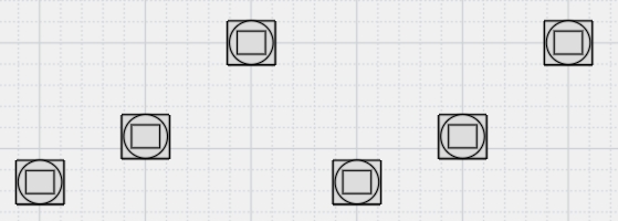
For common applications of tracking 3D position and orientation of Skeletons and Rigid Bodies, place the cameras on the periphery of the capture volume. This setup typically maximizes the camera overlap and minimizes wasted camera coverage. General tips include the following:
Mount cameras at the desired maximum height of the capture volume.
Distribute the cameras equidistantly around the setup area.
Adjust angles of cameras and aim them towards the target volume.
For cameras with rectangular FOVs, mount the cameras in landscape orientation. In very small setup areas, cameras can be aimed in portrait orientation to increase vertical coverage, but this typically reduces camera overlap, which can reduce marker continuity and data quality.
TIP: For capture setups involving large camera counts, it is useful to separate the capture volume into two or more sections. This reduces amount of computation load for the software.
Around the volume
For common applications tracking a Skeleton or a Rigid Body to obtain the 6 Degrees of Freedom (x,y,z-position and orientation) data, it is beneficial to arrange the cameras around the periphery of the capture volume for tracking markers both in front and back of the subject.
Camera Elevations
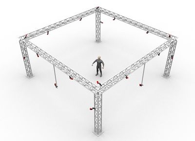
For typical motion capture setup, placing cameras at high elevations is recommended. Doing so maximizes the capture coverage in the volume, and also minimizes the chance of subjects bumping into the truss structure which can degrade calibration. Furthermore, when cameras are placed at low elevations and aimed across from one another, the synchronized IR illuminations from each camera will be detected, and will need to be masked from the 2D view.
However, it can be beneficial to place cameras at varying elevations. Doing so will provide more diverse viewing angles from both high and low elevations and can significantly increase the coverage of the volume. The frequency of marker occlusions will be reduced, and the accuracy of detecting the marker elevations will be improved.
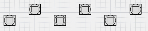
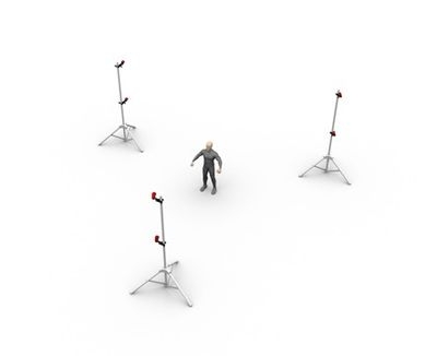
Camera to Camera Distance
Separating every camera by a consistent distance is recommended. When cameras are placed in close vicinity, they capture similar images on the tracked subject, and the extra image will not contribute to preventing occlusions or the reconstruction calculations. This overlap detracts from the benefit of a higher camera count and also doubles the computational load for the calibration process. Moreover, this also increases the chance of marker occlusions because markers will be blocked from multiple views simultaneously whenever obstacles are introduced.
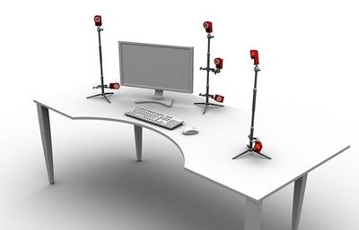
Camera to Object Distance
An ideal distance between a camera and the captured subject also depends on the purpose of the capture. A long distance between the camera and the object gives more camera coverage for larger volume setups. On the other hand, capturing at a short distance will have less camera coverage but the tracking measurements will be more accurate. The cameras lens focus ring may need to be adjusted for close-up tracking applications.
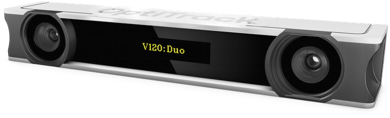
The OptiTrack Duo/Trio tracking bars are factory calibrated and there is no need to calibrate the cameras to use the system. By default, the tracking volume is set at the center origin of the cameras and the axis are oriented so that Z-axis is forward, Y-axis is up, X-axis is left.
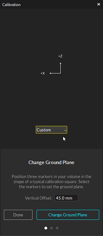
If you wish to change the location and orientation of the global axis, you can use the ground plane tools from the Calibration pane and use a Rigid Body or a calibration square to set the global origin.
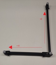
When using the Duo/Trio tracking bars, you can set the coordinate origin at the desired location and orientation using either a Rigid Body or a calibration square as a reference point. Using a calibration square will allow you to set the origin more accurately. You can also use a custom calibration square to set this.
Adjustig the Coordinate System Steps
First set place the calibration square at the desired origin. If you are using a Rigid Body, its pivot point position and orientation will be used as the reference.
[Motive] Open the Calibration pane.
[Motive] Open the Ground Planes page.
[Motive] Select the type of calibration square that will be used as a reference to set the global origin. Set it to Auto if you are using a calibration square from us. If you are using a Rigid Body, select the Rigid Body option from the drop-down menu. If you are using a custom calibration square, you will need to set the vertical offset also.
[Motive] Select the Calibration square markers or the Rigid Body markers from the Perspective View pane
[Motive] Click Set Set Ground Plane button, and the global origin will be adjusted.
You'll want to remove as much bloatware from your PC in order to optimize your system and make sure minimal unnecessary background processes are running. Background process can take up valuable CPU resources from Motive and cause frame drops while running your camera system.
There are many external resources in order to remove unused apps and halt unnecessary background processes, so they will not be covered within the scope of this page.
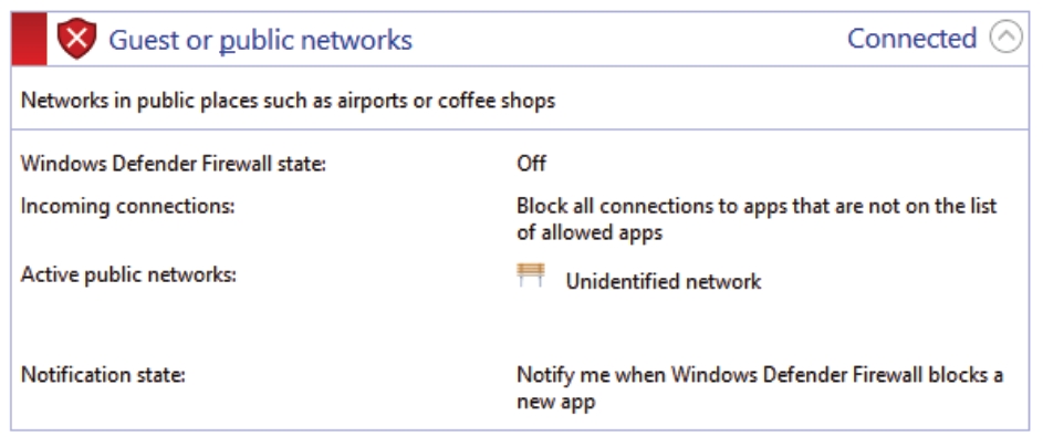
As a general rule for all OptiTrack camera systems, you'll want to disable all Windows firewalls and either disable or remove any Antivirus software. If firewalls and Antivirus software is enabled, this will cause frame drops while running your camera system.
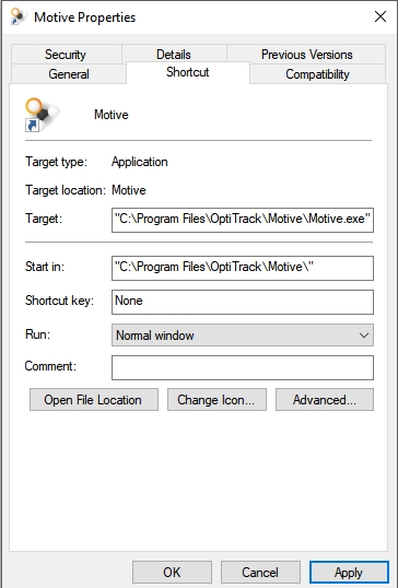
In order for Motive to run above other processes, you'll need to change the Priority of Motive.exe to High.
Right Click on the Motive shortcut from your Desktop
In the Target: text field enter the below path, this will allow Motive to run at High Priority that will persist from closing and reopening Motive.
C:\Windows\System32\cmd.exe /C start "" /high "C:\Program Files\OptiTrack\Motive\Motive.exe"
Please refrain from setting the priority to Realtime. If Realtime is selected, this can cause loss of input control (mouse, keyboard, etc.) since Windows can prioritize Motive above input processes.
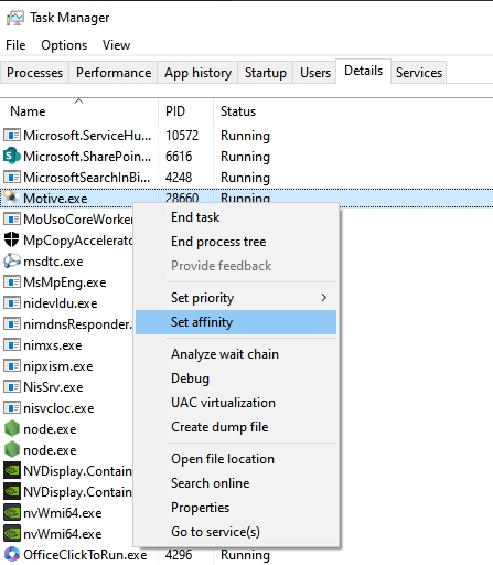
If you're running a system with a CPU with a lower core count, you may need to disable Motive from running on a couple of cores. This will help stabilize the overall system and free up some cores for other Windows required processes.
From the Task Manager, navigate to the Details tab and right click on Motive.exe
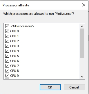
Select Set Affinity
From this window, uncheck the cores you wish to disallow Motive.exe to run on.
Click OK
Please note that you should only ever disable 2 cores or less to insure Motive still runs smoothly.
We recommend that you start with only one core and work your way up to two if you're still experiencing frame drop issues with your camera system.
The settings below are generally for larger camera setups and Prime Color camera setups. Typically, smaller systems will not need to use the settings below. When in doubt, please reach out to our Support team.
In most cases your switch settings will not be required to be altered. However, if your switch has built in Storm Control, you'll want to disable this feature.
Your Network Interface Card has a few settings that can change in order to optimize your system.
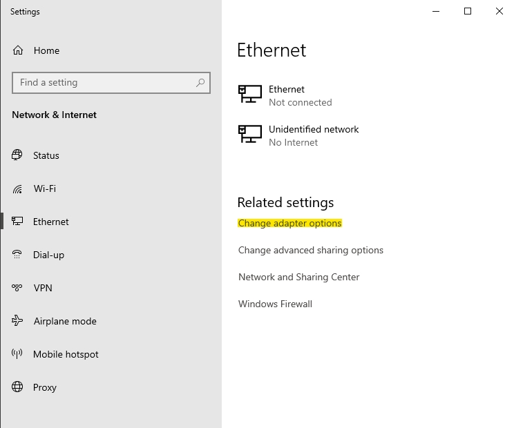
To navigate to the camera network's NIC:
Open Windows Settings
Select Ethernet from the navigation sidebar
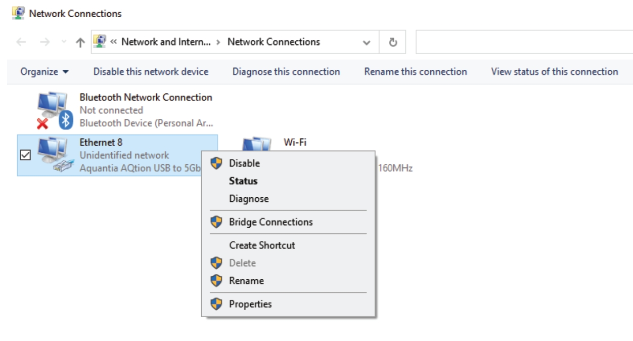
Under Related settings select Change adapter options
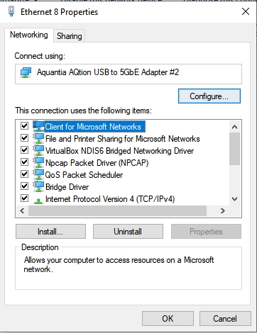
From the Network Connections pop up window, right click on your NIC and select Properites
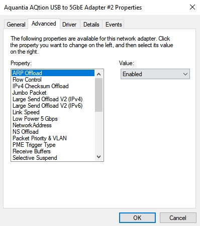
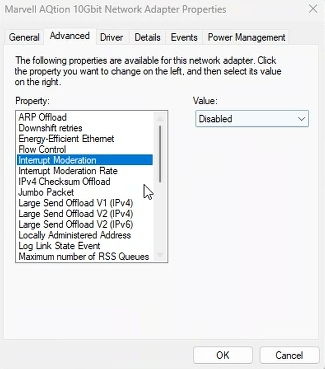
Select the Configure... button and navigate to the Advanced tab
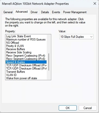
For the Speed and Duplex property, you'll want to change this to the highest throughput of your NIC. If you have a 10Gbps NIC, you'll want to make sure that 10Gbps Full Duplex is selected. This property allows the NIC to operate at it's full range. If this setting is not altered to Full, Windows has the tendency to throttle the NIC throughput causing a 10Gbps NIC to only be sending data at 2Gbps.
Interrupt Moderation allows the NIC to moderate interrupts. When there is a significant amount of data being uplinked to Motive, this can cause more interrupts to occur thus hindering the system performance. You'll want to Disable this property.
After the above properties have been applied, the NIC will need to go through a reboot process. This process is automatic, however, it will make it appear that your camera network is down for a few minutes. This is normal and once the NIC is rebooted, should begin to work as expected.
Although not recommended, you may use a laptop PC to run a larger or Prime Color Camera system. When using a laptop PC, you'll need to use an external network adapter for. The above settings will typically not apply to these types of adapters, so no properties will need to changed.
It is important to use a Thunderbolt port adapter with corresponding Thunderbolt ports on your laptop as opposed to a standard USB-C adapters/ports.
Before setting up a motion capture system, choose a suitable setup area and prepare it in order to achieve the best tracking performance. This page highlights some of the considerations to make when preparing the setup area for general tracking applications. Note that this page provides just general recommendations and these could vary depending on the size of a system or purpose of the capture.
First of all, pick a place to set up the capture volume.
Setup Area Size
System setup area depends on the size of the mocap system and how the cameras are positioned. To get a general idea, check out the Build Your Own feature on our website.
Make sure there is plenty of room for setting up the cameras. It is usually beneficial to have extra space in case the system setup needs to be altered. Also, pick an area where there is enough vertical spacing as well. Setting up the cameras at a high elevation is beneficial because it gives wider lines of sight for the cameras, providing a better coverage of the capture volume.
Minimal Foot Traffic
After camera system calibration, the system should remain unaltered in order to maintain the calibration quality. Physical contacts on cameras could change the setup, requiring it to be re-calibrated. To prevent such cases, pick a space where there is only minimal foot traffic.
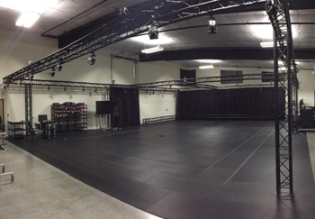
Flooring
Avoid reflective flooring. The IR lights from the cameras could be reflected by it and interfere with tracking. If this is inevitable, consider covering the floor with surface mats to prevent the reflections.
Avoid flexible or deformable flooring; such flooring can negatively impact your system's calibration.
For the best tracking performance, minimize ambient light interference within the setup area. The motion capture cameras track the markers by detecting reflected infrared light and any extraneous IR lights that exist within the capture volume could interfere with the tracking.
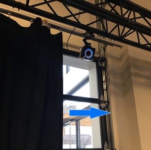
Sunlight: Block any open windows that might let sunlight in. Sunlight contains wavelength within the IR spectrum and could interfere with the cameras.
IR Light sources: Remove any unnecessary lights in IR wavelength range from the capture volume. IR lights could be emitted from sources such as incandescent, halogen, and high-pressure sodium lights or any other IR based devices.
All cameras are equipped with IR filters, so extraneous lights outside of the infrared spectrum (e.g. fluorescent lights) will not interfere with the cameras. IR lights that cannot be removed or blocked from the setup area can be masked in Motive using the Masking Tools during the system calibration. However, this feature completely discards image data within the masked regions and an overuse of it could negatively impact tracking. Thus, it is best to physically remove the object whenever possible.
Dark-colored objects absorb most of the visible light, however, it does not mean that they absorb the IR lights as well. Therefore, the color of the material is not a good way of determining whether an object will be visible within the IR spectrum. Some materials will look dark to human eyes but appear bright white on the IR cameras. If these items are placed within the tracking volume, they could introduce extraneous reconstructions.
Since you already have the IR cameras in hand, use one of the cameras to check whether there are IR white materials within the volume. If there are, move them out of the volume or cover them up.
Remove any unnecessary obstacles out of the capture volume since they could block cameras' view and prevent them from tracking the markers. Leave only the items that are necessary for the capture.
Remove reflective objects nearby or within the setup area since IR illumination from the cameras could be reflected by them. You can also use non-reflective tapes to cover the reflective parts.
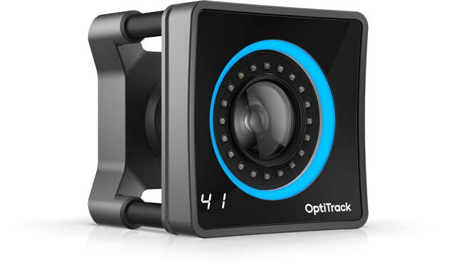
Prime 41 and Prime 17W cameras are equipped with powerful IR LED rings which enables tracking outdoors, even under the presence of some extraneous IR lights. The strong illumination from the Prime 41 cameras allows a mocap system to better distinguish marker reflections from extraneous illuminations. System settings and camera placements may need to be adjusted for outdoor tracking applications.
Please read through the Outdoor Tracking Setup page for more information.
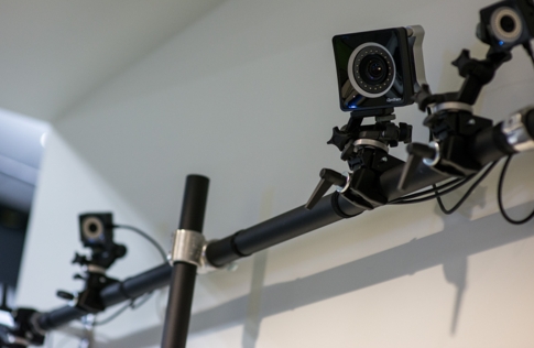
Choosing an appropriate camera mounting solution is very important when setting up a capture volume. A stable setup not only prevents camera damage from unexpected collisions, but it also maintains calibration quality throughout capture. All OptiTrack cameras have ¼-20 UNC Threaded holes – ¼ inch diameter, 20 threads/inch – which is the industry standard for mounting cameras. Before planning the mount structures, make sure that you have optimized your camera placement plans.
Due to thermal expansion issues when mounted to walls, we recommend using Trusses or Tripods as primary mounting structures.
Trusses will offer the most stability and are less prone to unwanted camera movement for more accurate tracking.
Tripods alternatively, offer more mobility to change the capture volume.
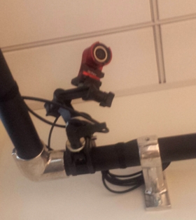
Wall Mounts and Speed Rails offer the ability to maximize space, but are the most susceptible to vibration from HVAC systems, thermal expansion, earthquake resistant buildings, etc. This vibration can cause inaccurate calibration and tracking.
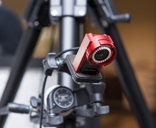
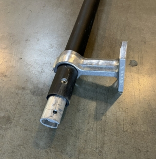
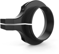
Camera clamps are used to fasten cameras onto stable mounting structures, such as a truss system, wall mounts, speed rails, or large tripods. There are some considerations when choosing a clamp for each camera. Most importantly, the clamps need to be able to bear the camera weight. Also, we recommend using clamps that offer adjustment of all 3 degrees of orientation: pitch, yaw, and roll. The stability of your mounting structure and the placement of each camera is very important for the quality of the mocap data, and as such we recommend using one of the mounting structures suggested in this page.
Here at OptiTrack, we recommend and provide Manfrotto clamps that have been tested and verified to ensure a solid hold on cameras and mounting structures. If you would like more information regarding Manfrotto clamps, please visit our Mounts and Tripods page on our website or reach out to our Sales team.
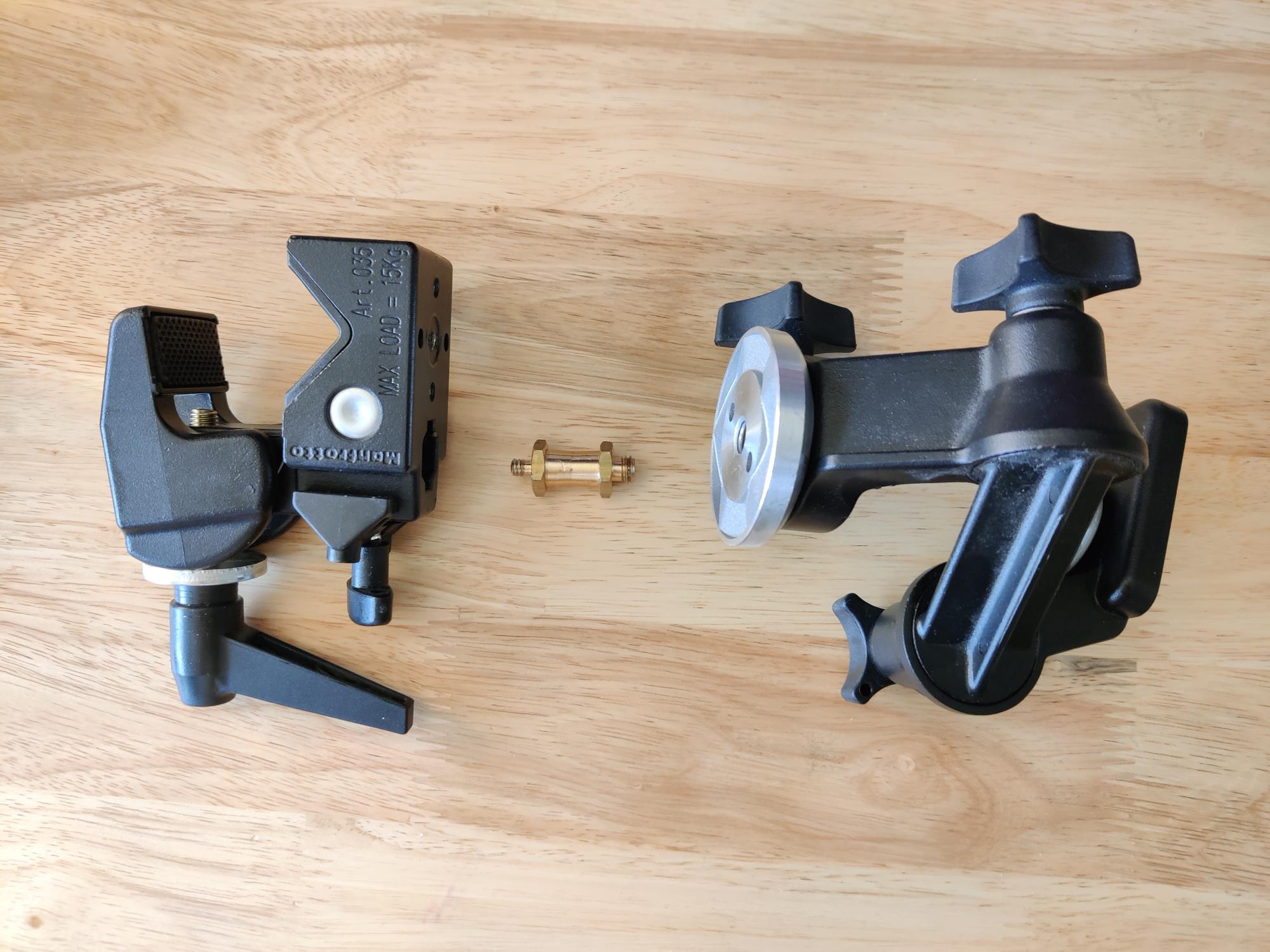
Manfrotto clamps come in three parts:
Manfrotto 035 Super Clamp
Manfrotto 056 3-Way, Pan-and-Tilt Head with 1/4"-20 Mount
Reversible Short Brass Stud
For proper assembly, please follow the steps below:
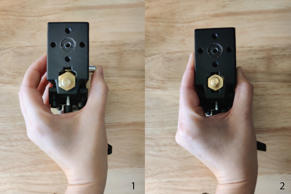
Place the brass stud into the 16mm hexagon socket in the Manfrotto Super Clamp.
Depress the spring-loaded button so the brass stud will lock into place.
Tighten the safety pin mechanism to secure the brass stud within the hexagon socket. Be sure that the 3/8″ screw (larger) end of the stud is facing out.
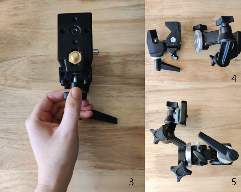
From here, attach the Super Clamp to the 3-Way, Pan-and-Tilt Head by screwing in the brass stud into the screw hole of the 3-Way, Pan-and-Tilt Head.
Be sure to tighten these two components fairly tight as you don't want them to swivel when installing cameras. It helps to first tighten the 360° swivel on the 3-Way, Pan-and-Tilt Head as this will ensure that any unwanted swivel will not occur when tightening the two components together.
Once, these two components are attached you should have a fully functioning clamp to attach your cameras to.
Large scale mounting structures, such as trusses and wall mounts, are the most stable and can be used to reliably cover larger volumes. Cameras are well-fixed and the need for recalibration is reduced. However, they are not easily portable and cannot be easily adjusted. On the other hand, smaller mounting structures, such as tripods and C-clamps, are more portable, simple to setup, and can be easily adjusted if needed. However, they are less stable and more vulnerable to external impacts, which can distort the camera position and the calibration. Choosing your mounting structure depends on the capture environment, the size of the volume, and the purpose of capture. You can use a combination of both methods as needed for unique applications.
Choosing an appropriate structure is critical in preparing the capture volume, and we recommend our customers consult our Sales Engineers for planning a layout for the camera mount setup.
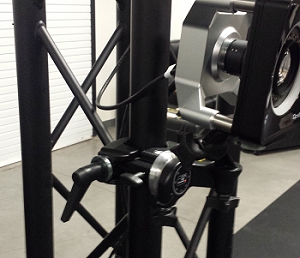
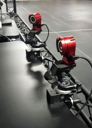
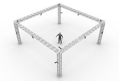
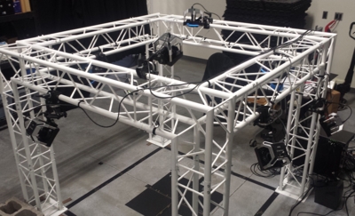
A truss system provides a sturdy structure and a customizable layout that can cover diverse capture volume sizes, ranging from a small volume to a very large volume. Cameras are mounted on the truss beam using the camera clamps.
Consult with the truss system provider or our Sales Engineers for setting up the truss system.
Follow the truss installation instruction and assemble the trusses on-site, and use the fastening pins to secure each truss segment.
Fasten the base truss to the ground.
Connect each of the segments and fix them by inserting a fastening pin.
Attach clamps to the cameras.
Mount the clamps to the truss beam.
Aim each camera.
Tripods are portable and simple to install, and they are not restricted to the environment constraints. There are various sizes and types of tripods for different applications. In order to ensure its stability, each tripod needs to be installed on a hard surface (e.g. concrete). Usually, one camera is attached per tripod, but camera clamps can be used in combination to fasten multiple cameras along the leg as long as the tripod is stable enough to bear the weight. Note that tripod setups are less stable and vulnerable to physical impacts. Any camera movements after calibration will distort the calibration quality, and the volume will need to be re-calibrated.
Wall mounts and speed rails are used with camera clamps to mount the cameras along the wall of the capture volume. This setup is very stable, and it has a low chance of getting interfered with by way of physical contact. The capture volume size and layout will depend on the size of the room. However, note that the wall, or the building itself, may slightly fluctuate due to the changing ambient temperature throughout the day. Therefore, you may need to routinely re-calibrate the volume if you are looking for precise measurements.
Below are recommended steps when installing speed rails onto different types of wall material. However, depending on your space, you may require alternative methods.
Although we have instructions below for installing speed rails, we highly recommend leaving the installation to qualified contractors.
General Tools
Cordless drill
Socket driver bits for drill
Various drill bits
Hex head Allen wrench set
Laser level
Speed Rail Parts
Pre-cut rails
Internal locking splice
5" offset wall mount bracket
End caps (should already be pre-installed onto pipes)
Elbow speed rail bracket (optional)
Tee speed rail bracket (optional)
Wood Stud Setup
Wood frame studs behind drywall requires:
Pre-drilled holes.
2 1/2" long x 5/16" hex head wood lag screws.
Metal Stud Framing Setup
Metal stud framing behind drywall requires:
Undersized pre-drilled holes as a marker in the drywall.
2"long x 5/16" self tapping metal screws with hex head.
Metal studs can strip easily if pre-drilled hole is too large.
Concrete Block/Wall Setup
Requires:
Pre-drilled holes.
Concrete anchors inserted into pre-drilled hole.
2 1/2" concrete lags.
Concrete anchors and lags must match for a proper fit.
It's easiest and safest to install with another person rather than installing by a single person and especially necessary when rails have been pre-inserted into brackets prior to installing on a wall.
Pre-drill bracket locations.
If working in a smaller space, slip speed rails into brackets prior to installing.
Install all brackets by the top lag first.
Check to see if all are correctly spaced and level.
Install bottom lags.
Slip speed rails into brackets.
Set screw and internal locking splice of speed rail.
Attach clamps to the cameras.
Attach the clamps to the rail.
Aim each camera.
Helpful Tips/Additional Information
The 5" offset wall brackets should not exceed 4' between each bracket.
Speed rails are shipped no longer than 8'.
Using blue painter's tape is a simple way to mark placement without messing up paint.
Make sure to slide the end of the speed rail without the end cap in first. If installed with the end-cap end first it will "mushroom" the end and make it difficult to slip brackets onto the speed rail.
Check brackets for any burs/sharpness and gently sand off to avoid the bracket scratching the finish on the speed rail.
To further reduce the bracket scratching the finish on the speed rail, use a piece of paper inside the bracket prior to sliding the speed rail through.
When enabled, the Broadcast Storm Control feature on the NETGEAR ProSafe GSM7228S may interfere with the transmission of data from OptiTrack Ethernet cameras. While this feature is critical to a corporate LAN or other network with internet access, it can cause dropped frames, loss of frame data, camera disconnection, and other issues on a camera system.
For proper system operations, the Storm Control feature must be disabled for all ports used in this aggregator switch. OptiTrack switches ship with these management features disabled.
Type Network in the Windows search bar to find and open the Control Panel to View Network Connections. The image below shows the three NICs specified above.
Double-click or right-click the NIC used to connect to the camera network and select Properties.
With IPv4 selected, click the Properties button.
Write down the IP address currently assigned to the Motive PC. You will need to change the address back to this once the switch configuration is updated.
Change the IP address to 169.254.100.200.
Enter 255.255.255.0 for the Subnet mask.
Click OK to save and return to the Properties window.
Open a browser window, enter 169.254.100.100, and press enter.
This will open the Admin Console for the switch.
Login to the switch with Username 'admin', and leave Password blank.
On the Security tab, click the Traffic Control subtab.
Select Storm Control -> Storm Control Global Configuration from the menu on the left.
Disable everything in the Port Settings options.
Click the Maintenance tab and select the Save Config subtab.
Select Save Configuration from the menu on the left.
Check the 'Save Configuration' check box. This will update the configuration and retain the new settings the next time the system is restarted.
Log out of the switch by closing the browser window.
Configure a Netgear PoE++ switch to connect a PrimeX 120 camera.
The Link Layer Discovery Protocol (IEEE 802.1AB) advertises the major capabilities and physical descriptions of components on an 802 Local Area Network. This protocol provides network components from different vendors the ability to communicate with each other.
LLDP also controls the Power over Ethernet (PoE) power allocation. In the case of the PrimeX 120 cameras, LLDP prevents the switch from providing sufficient power to the port where the camera is connected. For this reason, the LLDP protocol must be disabled on any port used to connect a PrimeX 120 to the camera network.
From the Motive PC, launch any web browser and type http://169.254.100.100 to open the Management Console for the switch.
This will open the login console.
Login using the Admin account.
If the switch has already been configured, the password is OptiPOE++. Otherwise, leave the password blank.
Click Main UI Login.
Set the values necessary to ensure the PrimeX 120 receives sufficient power once the LLDP settings are turned off.
On the System tab, select the PoE settings from the toolbar.
Click Advanced in the navigation bar, on the left.
Click PoE Port Configuration.
Select the port(s) to update.
Set the Max Power (W) value to 99.9.
Set the Power Limit Type to User.
Click the Apply button in the upper right corner to commit the changes in the current session.
Changes that are Applied but not Saved will remain in effect until the Switch is restarted, when the previous settings are restored. Configuration changes that are Saved will remain in effect after a restart.
Update settings to prevent LLDP from interfering with traffic from the PrimeX 120.
On the System tab, select the LLDP settings from the toolbar.
From the Navigation bar, select LLDP -> Interface Configuration.
Disable Transmit, Receive, and Notify for all required ports.
Click the Apply button in the upper right corner to commit the changes in the current session.
Storm control security features may throttle traffic from the PrimeX 120 cameras, affecting system performance.
On the Security tab, select the Traffic Control settings from the toolbar.
From the Navigation bar, select Storm Control -> Storm Control Global Configuration.
Disable all Port Settings shown.
Click the Apply button in the upper right corner to commit the changes in the current session.
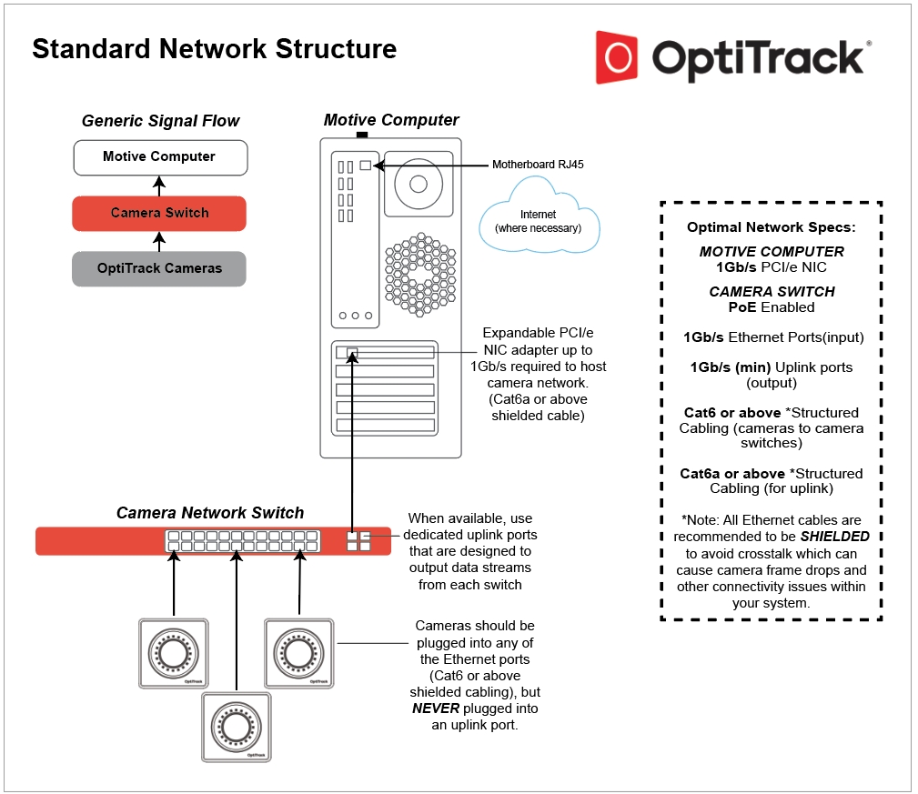
A guide to cabling and connecting your OptiTrack camera system.
PrimeX and SlimX cameras use Ethernet cables for power and to connect to the camera network. To handle the camera data throughput, cables and networking hardware (switches, NIC) must be able to transmit at 1 Gigabit to avoid data loss. For networks with color cameras or a large camera count, we recommend using a 10 Gigabit network.
For best performance, we recommend that all OptiTrack camera systems run on an independent, isolated network.
This page covers the following topics:
Switches and power load balancing.
Ethernet cable types and which cables to use in an OptiTrack system.
Recommended network configurations for small and large camera systems.
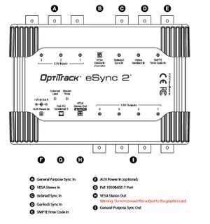
Adding an eSync2 for synchronization.
Checking for system errors in Motive.
Network switches form the backbone of an Ethernet-based OptiTrack camera system, providing the most reliable and direct communication between cameras and the Motive PC.
We thoroughly test and validate the switches we offer for quality and load balancing, and ship all products pre-configured for easy installation right out of the box.
For product specifications, please visit the section of our website. for additional information.
Switches also power the cameras. The total Watts a switch can provide is known as its Power (or PoE) Budget. The Watts needed to power all of the attached powered devices must be within the Power Budget for best performance.
The number of cameras any one switch can support varies based on the total amount of power drawn by the cameras. For example, a 65 W switch can run 4 PrimeX 13 PoE cameras, which require 15.4 W each to power:
4 x 15.4 W = 61.6 W
61.6 W < 65 W
If the total Watts required exceeds the Power Budget, cameras may experience power failures, causing random disconnects and reconnects, or they may fail to appear in Motive.
Network switches provided by OptiTrack include a label to specify the number of cameras supported:
Depending on which OptiTrack cameras are used, a switch may not have a large enough power budget to use every one of its ports. In a larger camera setup, this can result in multiple switches with unused ports. In this case, we recommend connecting each switch to a Redundant Power Supply (RPS) to extend its power budget.
For example, a 24-port switch may have a 370W power budget, supporting 12 PoE+ cameras that require 30W to power. If the same 24-port switch is connected to an RPS, it can now power all 24 PoE+ cameras (each with a 30W power requirement) utilizing all 24 of the ports on the switch.
PoE switches are categorized based on the maximum power level that individual ports can supply. The table below shows the power output of the various types of PoE switches and lists the current camera models that require each power level.
When calculating the number of switches needed, include the eSync2 (if used) and all BaseStations needed for the capture:
eSync2: 4.4W
BaseStation: 2.2W
A Small Form-Factor Pluggable Module (SFP Module) is a transceiver that inserts into an SFP port on the switch to allow the switch to accommodate different connection types than just the standard RJ45 Ethernet ports. This can include higher speed copper or fiber optic connections.
SFP modules work with specific brands and models of switches. Always confirm that the module is compatible with the switch before you purchase the SFP module.
Smaller systems may not need an SFP port to uplink camera data to Motive. OptiTrack offers an SFP module with switches intended for heavily loaded systems (i.e., those with larger camera counts or Prime Color Camera systems).
When SFP ports are not required, use any standard Ethernet port on the switch to uplink data to Motive.
Switches often include functions for managing network traffic that can interfere with the camera data and should be turned off. While these features are critical to a corporate LAN or other network with internet access, they can cause dropped frames, loss of frame data, camera disconnection, and other issues on a camera system.
For example, features such as Broadcast Storm Control may identify large data transmissions from the cameras as an attack on the network and potentially shut down the associated ports on the switch, disconnecting the camera(s) in the process.
OptiTrack switches ship with these management features disabled.
Ports on a switch can be partitioned into separate network segments known as Virtual Local Area Networks, or VLANs. Your IT department may use these to allow one switch to provide a virtually isolated network for the camera system and access to the corporate LAN and internet. This is not a supported configuration for an OptiTrack camera system.
OptiTrack does not support the use of VLANs for camera systems. If you are connected to a VLAN and are experiencing issues, we recommend truly isolating the camera system on its own switch.
There are multiple categories of Ethernet cables, each with different specifications for maximum data transmission rate and cable length.
*In general, the maximum cable length for an Ethernet cable is 100 m. While Cat7 and Cat8 cables can transmit data at higher rates, it reduces the maximum distance the data can travel before signal loss occurs.
Cat6a cables are recommended.
Cat5 or Cat5e cables run at lower speeds and are not supported.
Cat7 and Cat8 cables will work, but do not offer any added benefits to offset the increased cost.
What about fiber optic cables?
While fiber optic cables can transmit data over greater distances than Ethernet, they do not provide power and as such cannot be used to connect cameras.
A fiber optic connection can be used to connect to the Motive PC, but is not recommended unless the distance between the Motive PC and the switch is greater than 100 m.
Round cables are better for long distances and high data transmission speeds. They are more insulated, easier to install without issues, and more durable, making them our recommended choice.
Flat cables should not be used on an OptiTrack network as they are highly susceptible to cross talk and EMI.
Electromagnetic shielding protects cables from cross talk, electromagnetic interference (EMI), and radio frequency interference (RFI), all of which can result in loss of data or stalled cameras.
Shielding also protects the cameras from electrostatic discharge (ESD), which can damage them.
Ethernet cables are categorized based on the type of shielding they have overall and whether individual twisted pairs are also shielded.
As more shielding is added to a cable, its flexibility decreases and its weight increases. These factors should be taken into account prior to purchasing cables and in planning the overall weight-load of the speed rail used to mount the cameras.
Overall shielding wraps around all of the twisted pairs, directly below the PVC jacket. This shield can be a braided screen (S), foil (F), or both (SF). Cables without an overall shield are designated with a (U).
Individual Twisted pairs can be shielded with foil (FTP), or left unshielded (UTP).
Examples of cable shielding types:
S/UTP: The cable has a braided screen overall, with no shielding on the individual twisted pairs.
SF/FTP: The cable has two overall shields: a braided screen over a foil shield. The individual twisted pairs are shielded with foil.
U/UTP: The cable has no overall shield or shields on the individual twisted pairs. We do not recommend using these type of cables in an OptiTrack camera system.
Unshielded cables (U/UTP) do not protect the cameras from Electrostatic Discharge (ESD), which can damage the camera. Do not use unshielded cables in environments where ESD exposure is a risk.
Gaffers Tape: This offers a good solution for covering a small run of wires on the floor.
Labels: Label both ends of each cable before connecting the PC and cameras to the switch(es). This will allow you to easily identify the port where the camera is connected.
Velcro Strips: These work best for cable bundling in flexible setups. While Velcro may take more effort to remove then plastic zip ties, they can be reused multiple times and create less clutter when changes are made to the setup.
Truss Cable Management Clip: This is a specialty product used for Truss cabling. Clips help with cable organization, but can be size restrictive for a large bundle of cables.
Wire Conduit: These products cover the entire cable bundle. They are size-restrictive and can be difficult to put on or take off.
Floor Cable Covers: This product offers the best solution for covering floor cables, however they can be quite bulky.
In addition to camera count, the type of video being captured can affect the system's bandwidth needs. Reference video modes (Grayscale and MJPEG) and color video require significantly more bandwidth than object mode.
As noted above, always use 10 Gigabit shielded Ethernet cables (Cat6a or above) and a 10 Gigabit uplink switch to connect to the Motive PC, to accommodate the high data traffic. Make sure the NIC installed in the host PC can accommodate 10Gbps.
Start by connecting the Motive (host) PC to the camera network's PoE switch via a Cat6a Ethernet cable. When the network includes multiple switches, connect the host to the aggregator switch.
If the computer used for capture is also connected to an existing network, such as a Corporate LAN, use a second Ethernet port or add-on NIC to connect the computer to the camera network.
When the Motive PC is connected to multiple networks, disable all Windows Firewall settings while using the mocap system.
DO NOT connect any third-party devices to the camera network.
Connect any BaseStation(s) needed for the active devices directly to the aggregator switch, if used.
When the network includes multiple switches, connect the eSync2 to the aggregator switch. See the section below for more details on connecting the eSync2.
The switch(es) must be powered on to power the cameras. To completely shut down the camera system, power off the network switch(es).
For best performance, do not connect devices other than the computer to the camera network. Add-on network cards should be installed if additional Ethernet ports are required for the Motive PC.
These configurations have been tested for optimal use and safety. Deviating from them may negatively impact system performance.
A second switch can be connected to the primary switch via an uplink port, with the primary serving as the aggregation switch for the camera network. This is the only configuration where two camera switches can be daisy-chained together.
If additional switches are needed, a separate aggregation switch is required, so each switch has a direct connection to the aggregator. Please see the Multiple PoE Switches (High Camera Counts) tab for more details.
Uplink Switch: For systems that require multiple PoE switches, connect all of the switches to an uplink aggregation switch to link to the host PC. Ethernet ports on the aggregation switch can be used to connect cameras.
The switches must be connected in a star topology with the uplink switch at the central node, connecting to the Motive PC.
NEVER daisy chain multiple PoE switches in series; doing so can introduce latency to the system.
External devices can include timecode inputs such as Video Genlock or Precision Time Protocol, or output devices such as force plates or NI-DAQ devices.
Only one eSync2 is needed per system. When one is used, it is the master in the synchronization chain.
With large camera systems, connect the eSync to the aggregator switch via a standard Ethernet port for more stable camera synchronization.
The eSync2 includes a 12V power cable to power the sync hub separately if the aggregator switch doesn't support PoE.
The OptiTrack Duo/Trio tracking bars are factory calibrated and there is no need to calibrate the cameras to use the system. By default, the tracking volume is set at the center origin of the cameras and the axis are oriented so that Z-axis is forward, Y-axis is up, X-axis is left.
If you wish to change the location and orientation of the global axis, you can use the Coordinate Systems Tool which can be found under the Tools tab.
Adjusting the Coordinate System Steps
Place the calibration square at the desired origin.
[Motive] Open the Coordinate System Tools pane under the Tools tab.
[Motive] Click the Set Ground Plane button from the Coordinate System Tools pane, and the global origin will be adjusted.
The API reports "world-space" values for markers and rigid body objects at each frame. It is often desirable to convert the coordinates of points reported by the API from the world-space (or global) coordinates into the local space of the rigid body. This is useful, for example, if you have a rigid body that defines the world space that you want to track markers within.
Rotation values are reported as both quaternions, and as roll, pitch, and yaw angles (in degrees). Quaternions are a four-dimensional rotation representation that provide greater mathematical robustness by avoiding "gimbal" points that may be encountered when using roll, pitch, and yaw (also known as Euler angles). However, quaternions are also more mathematically complex and are more difficult to visualize, which is why many still prefer to use Euler angles.
There are many potential combinations of Euler angles so it is important to understand the order in which rotations are applied, the handedness of the coordinate system, and the axis (positive or negative) that each rotation is applied about.
These are the conventions used in the API for Euler angles:
Rotation order: XYZ
All coordinates are *right-handed*
To create a transform matrix that converts from world coordinates into the local coordinate system of your chosen rigid body, you will first want to compose the local-to-world transform matrix of the rigid body, then invert it to create a world-to-local transform matrix.
To compose the rigid body local-to-world transform matrix from values reported by the API, you can first compose a rotation matrix from the quaternion rotation value or from the yaw, pitch, and roll angles, then inject the rigid body translation values. Transform matrices can be defined as either "column-major" or "row-major". In a column-major transform matrix, the translation values appear in the right-most column of the 4x4 transform matrix. For purposes of this article, column-major transform matrices will be used. It is beyond the scope of this article, but it is just as feasible to use row-major matrices by transposing matrices.
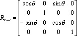
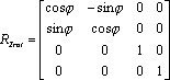
In general, given a world transform matrix of the form: M = [ [ ] Tx ] [ [ R ] Ty ] [ [ ] Tz ] [ 0 0 0 1 ]
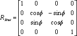
where Tx, Tz, Tz are the world-space position of the origin (of the rigid body, as reported from the API), and R is a 3x3 rotation matrix composed as: R = [ Rx (Pitch) ] * [ Ry (Yaw) ] * [ Rz (Roll) ]
where Rx, Ry, and Rz are 3x3 rotation matrices composed according to:
A handy trick to know about local-to-world transform matrices is that once the matrix is composed, it can be validated by examining each column in the matrix. The first three rows of Column 1 are the (normalized) XYZ direction vector of the world-space X axis, column 2 holds the Y axis, and column 3 is the Z axis. Column 4, as noted previously, is the location of the world-space origin. To convert a point from world coordinates (coordinates reported by the API for a 3D point anywhere in space), you need a matrix that converts from world space to local space. We have a local-to-world matrix (where the local coordinates are defined as the coordinate system of the rigid body used to compose the transform matrix), so inverting that matrix will yield a world-to-local transformation matrix. Inversion of a general 4x4 matrix can be slightly complex and may result in singularities, however we are dealing with a special transform matrix that only contains rotations and a translation. Because of that, we can take advantage of the method shown here to easily invert the matrix:
Once the world matrix is converted, multiplying it by the coordinates of a world-space point will yield a point in the local space of the rigid body. Any number of points can be multiplied by this inverted matrix to transform them from world (API) coordinates to local (rigid body) coordinates.
The API includes a sample (markers.sln/markers.cpp) that demonstrates this exact usage.
General specifications to setup an OptiTrack camera system on an Ethernet network.
Please see our and pages for detailed setup instructions for an Ethernet camera system.
An Ethernet camera system uses Ethernet switches and cables to connect to the Motive PC. Ethernet-based camera models include PrimeX series (PrimeX 13, 13W, 22, 41, 120), SlimX series (SlimX 13, 120), and Prime Color models.
Ethernet cables not only offer faster data transfer rates, but they also provide power over Ethernet to each camera while transferring the data to the host PC. This reduces the number of cables required and simplifies the overall setup. With a maximum length of 100m, Ethernet cables allow coverage over large volumes.
Host PC with an isolated network card for the camera system (PCI/e NIC)
Ethernet Cameras
Ethernet cables
Ethernet PoE/PoE+/PoE++ Switch(es)
Uplink switch (for a large camera count setup)
The eSync2 (optional for synchronizations)
Cable Type
There are multiple categories of Ethernet cables, and each has different specifications for maximum data transmission rate and cable length. For an Ethernet based system, Cat6 or above Gigabit Ethernet cables should be used. 10 Gigabit Ethernet cables – Cat6a or above — are recommended in conjunction with a 10 Gigabit uplink switch for the connection between the uplink switch and the host PC in order to accommodate for high data traffic.
Note
10Gb uplink switches, NICs, and cables are recommended for large camera counts or high data cameras like the Prime Color cameras. Typically 1Gb switches, NICs, and cables should be enough to accommodate smaller and moderately sized systems. If you're unsure whether you need more than 1Gb, please contact one of our or see our page for more information.
Electromagnetic Shielding
We recommend using only cables that have electromagnetic interference shielding. If unshielded cables are used, cables in close proximity to each other have the potential to create data transfer interference and cause cameras to stall in Motive.
Unshielded cables do not protect the cameras from Electrostatic Discharge (ESD), which can damage the camera. Do not use unshielded cables in environments where ESD exposure is a risk.
Our current general standard for network switches are:
PoE ports with at least 1 Gigabit of data transfer for each port.
We thoroughly test and validate the switches we offer for quality and load balancing, and ship all products pre-configured for easy installation right out of the box.
Our team cannot support switches that were not purchased from OptiTrack.
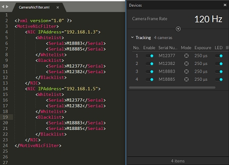
This page provides instructions on how to configure the CameraNicFilter.xml file to whitelist or blacklist specific cameras from the connected camera network.
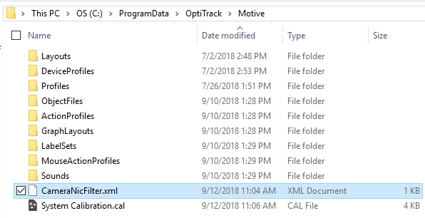
Starting with Motive 2.1, you can specify which cameras to utilize among the connected Ethernet cameras in a system. This can be done by setting up an XML file (CameraNicFilter.xml) and placing it in Motive's ProgramData directory: C:\ProgramData\OptiTrack\Motive\CameraNicFilter.xml. Once this is set, Motive will initialize only the specified cameras within the respective network interface. This allows users to distribute the cameras to specific network interfaces on a computer or on multiple computers.
Additional Note:
This filter works with Ethernet camera systems only. USB camera systems are not supported.
At the time of writing, the eSync is NOT supported. In other words, the eSync cannot be present in the system in order for the filter to work properly.
For common applications, there is usually no need to separate the cameras to different network interfaces. However, there are few situations where you may want to use this filter to segregate the cameras. Below are some of the sample applications of the filters:
Multiple Prime Color cameras
When there are multiple Prime Color cameras in a setup, you can configure the filter to spread out the data load. In other words, you can uplink color camera data through a separate network interface (NIC) and distribute the data traffic to prevent any bandwidth bottleneck. To accomplish this, multiple NICs must be present on the host computer, and you can distribute the data and uplink them onto different interfaces.
Active marker tracking on multiple capture volumes
For , this filter can be used to distribute the cameras to different host computers. By doing so, you can segregate the cameras into multiple capture volumes and have them share the same connected BaseStation. This could be beneficial for VR applications especially if you plan on having multiple volumes to calibrate because you can use the same active components between different volumes.
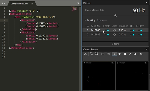
To separate the cameras, you will need to use a text editor to create an XML file named CameraNicfilter.xml. In this XML file, you will specify which cameras to whitelist or blacklist within the connected network interface. Please note that it is very important for the XML file to match the expected format; for this reason, we strongly recommend to first copy-and-paste the template and start from there.
Attached below is a basic template of the CameraNicFilter.xml file. On each NIC element, you can specify each network interface using the IPAddress attribute, and then in its child elements, you can specifically set which cameras to whitelist or blacklist using their serial numbers.
For each network interface that you will be using to communicate with the cameras, you will need to create a <NIC> element and assign a network IP address (IPv4) to its IPAddress attribute. Then, under each NIC element, you can specify which cameras to use or not to use.
Please make sure correct IP addresses are assigned when configuring the NIC element. Run the ipconfig command on the windows command prompt to list out the assigned IP addresses of the available networks on the computer and then use the IPv4 address of the network that you wish to use. When necessary, you can also set a static IP address for the network interface and use a known address value for easier setup.
Under the NIC element, define two child elements: <Whitelist> and <Blacklist>. In each element, you will be specifying the cameras using their serial numbers. Within each network interface, only the cameras listed under the <Whitelist> element will be used and all of the cameras under <Blacklist> will be ignored.
As shown in the above template, you can specify which cameras to whitelist or blacklist using the corresponding camera serial numbers. For example, you can use the following to specify the camera (M18883) <Serial>M18883</Serial>. You can also use a partial serial number as a wildcard to specify all cameras with the matching serial number. For example, if you wish to blacklist all Color cameras in a network (192.168.1.3), you can use C as the wildcard serial number since the serial number of all color cameras start with C.
Once the XMl file is configured, please save the file in the ProgramData directory: C:\ProgramData\OptiTrack\Motive\CameraNicFilter.xml. If everything is set up properly, only the whitelisted cameras under each network interface will get initialized in Motive, and the data from only the specified cameras will be uplinked through the respective network interface.
Repeat to access and change the network settings for the NIC used to access the switch. Set the IP address back to the address it was originally.
Click the Save button to save the changes to the startup configuration.
Click the Save button to save the changes to the startup configuration.
Click the Save button to save the changes to the startup configuration.
If you're unsure if you need an switch with an SFP port and an SFP module, please reach out to either our or teams.
The number of cameras in the system determine how the network is configured. The show the recommended wiring setup for either a small or large camera system.
Using Cat6a or above cables, connect the individual cameras to the Ethernet switch based on the scheme established when designing the camera network.
Use an synchronization hub to connect external devices such as force plates or Video Genlock to the camera network. The eSync connects to the PoE switch using an Ethernet cable.
The is a synchronization hub used to integrate external devices to an Ethernet-based mocap system. The set the timecode, input trigger, and other settings to ensure all devices on the camera network are in sync.
All of the connected cameras should now be listed in the and display in the when you start Motive. Make sure all of the connected cameras are properly listed in Motive.
Open the status and verify there are no current errors. The example below shows the sequence of errors that occur when a camera is disconnected. Look also for dropped frames, which may indicate a problem with how the system is delivering the camera data. Please refer to the for more details.
When using the Duo/Trio tracking bars, you can set the coordinate origin at a desired location and orientation using a . Make sure the calibration square is oriented properly.
[Motive] Select the Calibration square markers from the
A power budget that is able to support the desired number of cameras. If the number of cameras exceeds the power budget of a single switch, additional switches may be used, with an uplink switch to connect the switches. Please see the page for more information.
For specific brands/models of switches, please .
For product specifications, please visit the section of our website. for additional information.
For issues connecting the cameras to the switches provided by OptiTrack, please see the page or contact our .
A: 2D frame drops are logged under the and can also be seen in the . It will be indicated with a warning sign next to the corresponding camera. If the system continues to drop 2D frames, it means there is a problem with receiving the camera data. In many cases, this occurs due to networking problems.
To narrow down the issue, disable the in the Properties pane for that camera and check if the frames are still dropping. If it stops, the problem is associated with either the software configuration or CPU processing. If frames continue to drop, then the problem could be narrowed down to the network configuration, which may be resolved by doing the following:
If the cameras are still not detected, . Launch Motive and note how the back LED lights on the cameras are flashing. This will help Support troubleshoot the issue.
Check the serial numbers for the cameras against the compatibility notes for your version on our page.
PoE
15.4 W
PrimeX 13, SlimX 13
PoE+
30 W
PrimeX 22, PrimeX 41, SlimX 120, Prime Color
PoE++
71 - 90 W (based on length)
PrimeX 120
Cat6
10 Gb/s (55 m)
250 MHz
6.1 mm
Cat6a
10 Gb/s (100 m)
500 MHz
8.38 mm
Cat7/a
100 Gb/s (15 m*)
600 or 1000 MHz
8.51 mm
Cat8
40 Gb/s (30 m*)
2000 MHz
8.66 mm


This page includes information on the status indicator lights on the OptiTrack Ethernet cameras.
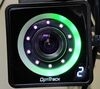
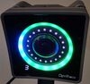
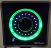
The PrimeX Series cameras have a front mounted status ring light to indicate the state of the Motive software and firmware updates on the cameras. The following table lists the default ring light color associated with the state of Motive.
Status Ring Light Colors
Off
Powered & Awaiting Connection
When camera is first plugged in the LED ring light will be off until it receives commands from Motive and has successfully authenticated via the security key. If it is not successful in connecting to the network, but receiving power it will remain off with a small flashing white dot light in the bottom left corner.
No
Slow Flashing Cyan, no IR
Idle
Powered and connected to network, but Motive is not running. Two dashes in the bottom left corner will be present in lieu of ID number.
No
Cyan
Live
Actively sending data and receiving commands when loaded into Motive.
Yes
White/Off
Masking
When a marker, or what a camera perceives as a marker, is visible to a camera when masking in the Calibration pane, the status light will turn white. When masks are applied and no erroneous marker data is seen, the LEDs turn off and the volume is ready to wand.
No
Solid Green
Recording
Camera is sending data to be written to memory or disk.
Yes
Variable Green
Sampling During Calibration
Camera starts out black, then green will appear on the ring light depending on where you have wanded relative to that camera.
When the camera starts to take samples, there will be a white light that follows the wand movement rotating around the LED.
This will fill in dark green and then light green when enough samples are taken.
No
Flashing White
Calibration
During calibration when cameras have collected sufficient data they will turn green. Once enough cameras have collected enough samples the left over cameras will flash white indicating they still need to collect more samples for a successful calibration.
No
None
Playback
Camera is operating but Motive is in Edit Mode.
Yes
Yellow
Selected
Camera is selected in Motive.
Yes
Red
Reference
Camera is in reference mode. Instead of capturing the marker data, the camera is recording reference video, Greyscale and MJPEG
Yes
Cycle Red
Firmware Reset
On board flash memory is being reset.
No
Cycle Cyan
Firmware Update
For PrimeX cameras. Firmware is being written to flash. On completion, color turns off and camera reboots.
No
Cycle Yellow
Firmware Update
For Prime cameras. Firmware is being written to flash. On completion, color turns off and camera reboots.
No
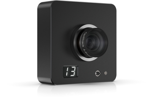
On every PrimeX camera there is an additional display in the bottom left corner of the face of the camera.
Bottom Left Display Values
Cycling Numbers
Camera is in the process of updating the firmware. The numbers will start at 0 and increase to 100 indicating that the firmware has completed 100% of the update.
Constant Number
This is the number of the camera as assigned by Motive. Every time Motive is closed and reopened or a camera is removed from the system, the number will update accordingly.
'E'
If an 'E' error code appears in the display this means that the camera has lost connection to the network. To troubleshoot this, start by unplugging the camera and plugging it back into the camera switch. Alternatively, you may also try restarting the entire switch to reset the entire network.
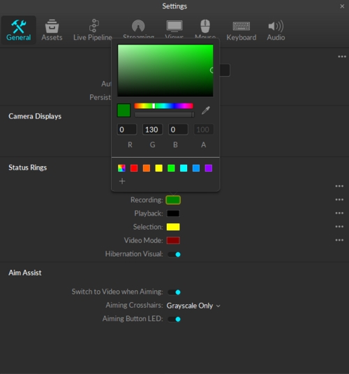
If for any reason you need to change the status ring light you can do so by going into Settings and under General click on the color box next to the status you would like to change. This will bring up a color picker window where you can choose a solid color or choose mutli-color to oscillate between colors. You also have the ability to save a color to your color library to apply it to other statuses.
In order to disable the aim assist button LED on the back of PrimeX cameras, you simply toggle them off in the General settings. You can find this under Aim Assist > Aiming Button LED.
The PrimeX Series cameras also have a status indicator on the back panel and indicate the state of the camera only. When changing to a new version of Motive, the camera will need a firmware update in order to communicate to the new version. Firmware updates are automatic when starting Motives. If the camera's firmware updates to a new version of Motive, running an older version of Motive will cause the firmware to necessarily revert back to an older version of firmware. This process is automatic as well.
Back Ring Light Colors
Green
Initialize Phase 1
Camera is powered and boot loader is running. Preparing to run main firmware.
Yellow
Initialize Phase 2
Firmware is running and switch communication in progress.
Blinking Green (Slow)
Initialize Phase 3
Switch communication established and awaiting an IP address.
Cyan
Firmware Loading
Host has initiated firmware upload process.
Blinking Yellow
Initialize Phase 4
Camera has fully initialized. In process of synchronizing with camera group or eSync.
Blinking Green (Fast)
Running
Camera is fully operational and synchronized to the camera group. Ready for data capture.
Blue
Hibernating
Camera is in a low power state and not sending data. Occurs after closing Motive but leaving the cameras connected to the switch.
Alternating Red
Firmware Reset
On board flash memory is being reset.
Alternating Yellow
Firmware Update
Firmware is being written to flash. Numeric display in front will show progress. On completion, the light turns green and camera reboots.
When changing versions of Motive, a firmware update is needed. This process is automatic when opening the software and the status ring light and back ring light show the state, as described in the table above, of the camera during this process. The camera should not be unplugged during a firmware reset or firmware update. Give the camera time to finish this process before turning off the software.
If a camera doesn't update its firmware with the rest of the cameras, it will not get loaded into Motive. Wait for all cameras that are updating to finish, then restart Motive. The cameras that failed to update will now update. This could be caused by miscommunication between the switch when loading in numerous cameras.
Blue
Actively sending data and receiving commands when loaded into Motive.
Green
Camera is sending data to be written to memory or disk.
None
Camera is operating but Motive is in Edit Mode.
Yellow
Camera is selected in Motive.
Orange
Camera is in reference mode. Instead of capturing the marker data, the camera is recording reference video, MJPEG
Blinking red on start up
Firmware update is in progress, which is normal. Firmware will be updated when a new version of Motive is installed on the computer.
If the LED blinks in red a few times about 15 seconds after the camera start-up, it means that the camera has failed to establish a connection with the PoE switch. When this happens, error sign, E or E1, will be shown on the numeric display.
Yellow on start up
The camera is attempting to establish a link with the PoE switch.
Like PrimeX series cameras, SlimX 13 cameras also have a status indicator on the back panel and indicate the state of the camera.
Back Ring Light Colors
Green
Initialize Phase 1
Camera is powered and boot loader is running. Preparing to run main firmware.
Yellow
Initialize Phase 2
Firmware is running and switch communication in progress.
Blinking Green (Slow)
Initialize Phase 3
Switch communication established and awaiting an IP address.
Cyan
Firmware Loading
Host has initiated firmware upload process.
Blinking Yellow
Initialize Phase 4
Camera has fully initialized. In process of synchronizing with camera group or eSync2.
Blinking Green (Fast)
Running
Camera is fully operational and synchronized to the camera group. Ready for data capture.
Blue
Hibernating
Camera is in a low power state and not sending data. Occurs after closing Motive but leaving the cameras connected to the switch.
Alternating Red
Firmware Reset
On board flash memory is being reset.
Alternating Yellow
Firmware Update
Firmware is being written to flash. Numeric display in front will show progress. On completion, the light turns green and camera reboots.
A USB camera system provides high-quality motion capture for small to medium size volumes at an affordable price range. USB camera models include the Flex series (Flex 3 and Flex 13) and Slim 3U models. USB cameras are powered by the OptiHub, which is designed to maximize the capacity of Flex series cameras by providing sufficient power to each camera, allowing tracking at long ranges.
For each USB system, up to four OptiHubs can be used. When incorporating multiple OptiHubs in the system, use RCA synchronization cables to interconnect each hub. A USB system is not suitable for a large volume setup because the USB 2.0 cables used to wire the cameras have a 5-meter length limitation.
If needed, up to two active USB extensions can be used when connecting the OptiHub to the host PC. However, the extensions should not be used between the OptiHub and the cameras. We do not support using more than 2 USB extensions anywhere on a USB 2.0 system running Motive.
Main Components
Host PC
USB Cameras
OptiHub(s) and a power supply for each hub.
USB 2.0 cables:
USB 2.0 Type A/B per OptiHub.
USB 2.0 Type B/mini-b per camera.
OptiHub
The OptiHub is a custom-engineered USB hub that is designed to be incorporated in a USB camera system. It provides both power and external synchronization options. Standard USB ports do not provide enough power for the IR illumination within Flex 13 cameras and they need to be routed through an OptiHub in order to activate the LED array.
USB Load Balancing
When connecting hubs to the computer, load balancing becomes important. Most computers have several USB ports on the front and back, all of which go through two USB controllers. Especially for a large camera count systems (18+ cameras), it is recommended that you evenly split the cameras between the USB controllers to make the best use of the available bandwidth.
OptiSync
OptiSync is a custom synchronization protocol which sends the synchronization signals through the USB cable. It allows each camera to have one USB cable for both data transfer and synchronization instead of having separate USB and daisy-chained RCA synchronization cables as in the older models.
Difference Between OptiSync and Wired Sync
OptiSync
The OptiSync is a custom camera-to-camera synchronization protocol designed for Flex series cameras. The OptiSync protocol sends and receives sync signals over the USB cable, without the need for RCA sync cables. This sync method is only available when using Flex 3 or Flex 13 cameras connected to the OptiHub.
Wired Sync
The Wired Sync is a camera-to-camera synchronization protocol using RCA cables in a daisy chain arrangement. With a master RCA sync cable connecting the master camera to the OptiHub, each camera in the system is connected in series via RCA sync cables and splitters. The V100:R1 (Legacy) and the Slim 3U cameras utilize Wired Sync only, and therefore any OptiTrack system containing these cameras need to be synchronized through the Wired Sync. Wired Sync is optionally available for Flex 3 cameras.
At this point, all of the connected cameras will be listed on the Devices pane and the 3D viewport when you start up Motive. Check to make sure all of the connected cameras are properly listed in Motive.
Then, open up the Status Log panel and check there are no 2D frame drops. You may see a few frame drops when booting up the system or when switching between Live and Edit modes; however, this should only occur just momentarily. If the system continues to drop 2D frames, it indicates there is a problem with how the system is delivering the camera data. Please refer to the troubleshooting section for more details.
In order to ensure that every camera in a mocap system takes full advantage of its capability, they need to be focused and aimed at the target tracking volume. This page includes detailed instructions on how to adjust the focus and aim of each camera for an optimal motion capture. OptiTrack cameras are focused at infinity by default, which is generally sufficient for common tracking applications. However, we recommend users always double-check the camera view and make sure the captured images are focused when first setting up the system. Obtaining best quality image is very important as 3D data is derived from the captured images.
Make sure that the camera placement is appropriate for your application.
Pick a camera to adjust the aim and focus.
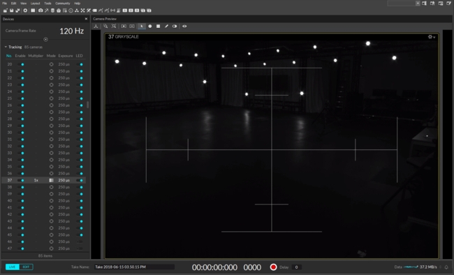
Set the camera to the raw grayscale video mode (in Motive) and increase the camera exposure to capture the brightest image (These steps are accomplished by the Aim Assist Button on featured cameras).
Place one or more reflective markers in the tracking volume.
Carefully adjust the camera angle while monitoring the Camera Preview so that the desired capture volume is included within the camera coverage.
Within the Camera Preview in Motive, zoom in on one of the markers so that it fills the frame.
Adjust the focus (detailed instruction given below) so that the captured image is resolved as clearly as possible.
Repeat above steps for other cameras in the system.
Adjusting aim with a single person can be difficult because the user will have to run back and forth from the camera and the host PC in order to adjust the camera angle and monitor the 2D view at the same time. OptiTrack cameras featuring the Aim Assist button (Prime series and Flex 13) make this aiming process easier. With just one button-click, the user can set the camera to the grayscale mode and the exposure value to its optimal setting for adjusting both aim and focus. Fit the capture volume within the vertical and horizontal range shown by the virtual crosshairs that appear when Aim Assist mode is on. With this feature, the single-user no longer needs to go back to the host PC to choose cameras and change their settings. Settings for Aim Assist buttons are available from Application Settings pane.
After all the cameras are placed at correct locations, they need to be properly aimed in order to fully utilize their capture coverage. In general, all cameras need to be aimed at the target capture volume where markers will be tracked. While cameras are still attached to the mounting structure, carefully adjust the camera clamp so that the camera field of view (FOV) is directed at the capture region. Refer to 2D camera views from the Camera Preview pane to ensure that each camera view covers the desired capture region.
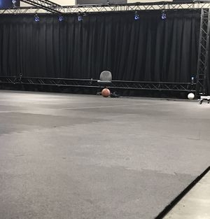
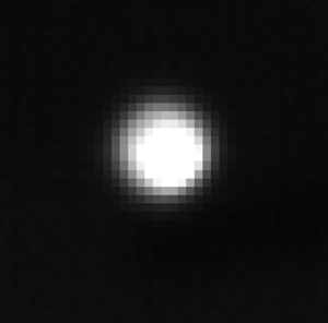
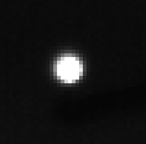
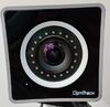
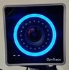
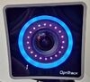
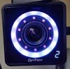
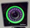
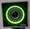
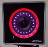
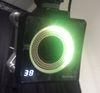
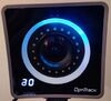
All OptiTrack cameras (except the V120:Duo/Trio tracking bars) can be re-focused to optimize image clarity at any distance within the tracking range. Change the camera mode to raw grayscale mode and adjust the camera setting, increase exposure and LED setting, to capture the brightest image. Zoom onto one of the reflective markers in the capture volume and check clarity of the image. Then, adjust the camera focus and find the point where the marker image is best resolved. The following images show some examples.
Auto-zoom using Aim Assist button
Double-click on the aim assist button to have the software automatically zoom into a single marker near the center of the camera view. This makes the focusing process easier to accomplish for a single person.
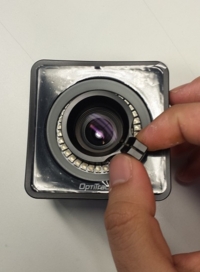
PrimeX 41 and PrimeX 22
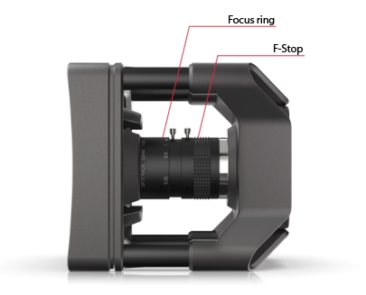
For PrimeX 41 and 22 models, camera focus can be adjusted by rotating the focus ring on the lens body, which can be accessed at the center of the camera. The front ring on the lens changes the focus of the camera, and the rear ring adjusts the F-stop of the lens. In most cases, it is beneficial to set the f-stop low to have the aperture at its maximum size for capturing the brightest image. Carefully rotate the focus ring while monitoring the 2D grayscale camera view for image clarity. Once the focus and f-stop have been optimized on the lens, it should be locked down by tightening the set screw. In default configuration, PrimeX 41 cameras are equipped with 12mm F#1.8 lens, and the PrimeX 22 cameras are equipped with 6.8mm F#1.6 lens.
Prime 17W and 41*
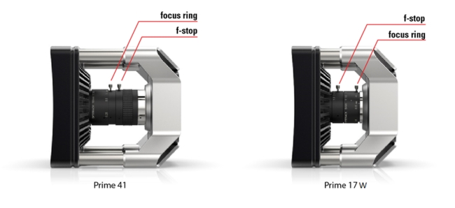
For Prime 17W and 41 models, camera focus can be adjusted by rotating the focus ring on the lens body, which can be accessed at the center of the camera. The front ring on the Prime 41 lens changes the focus of the camera, while the rear ring on the Prime 17W adjusts its focus. Set the aperture at its maximum size in order to capture the brightest image. For the Prime 41, the aperture ring is located at the rear of the lens body, where the Prime 17W aperture ring is located at the front. Carefully rotate the focus ring while monitoring the 2D grayscale camera view for image clarity. Align the mark with the infinity symbol when setting the focus back to infinity. Once the focus has been optimized, it should be locked down by tightening the set screw.
*Legacy camera models
PrimeX 13 and 13W, and Prime 13* and 13W*
PrimeX 13 and PrimeX 13W use M12 lenses and cameras can be focused using custom focus tools to rotate the lens body. Focusing tools can be purchased on OptiTrack’s Lens Accessories page, and they clip onto the camera lens and rotates it without opening the camera housing. It could be beneficial to lower the LED illumination to minimize reflections from the adjusting hand.
*Legacy camera models
Slim Series
SlimX 13 cameras also feature M12 lenses. The camera focus can be easily adjusted by rotating the lens without the need to remove the housing. Slim cameras support multiple lens types, including third-party lenses so focus techniques will vary. Refer to the lens type to determine how to proceed. (In general, M12 lenses will be focused by rotating the lens body, while C and CS lenses will be focused by rotating the focus ring).
0 to 50 degrees Celsius
20% to 80% relative humidity (non-condensing)
Download the Motive 3.1 software installer from the Motive Download Page to each host PC.
Run the installer and follow its prompts.
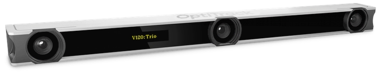
Each V120:Duo and V120:Trio includes a free license to Motive:Tracker for one device. No software license activation or security key is required.
To use multiple V120 devices, connect each one to a separate host PC with Motive installed.
Please see the Host PC Requirements section of the Installation and Activation page for computer specifications.
V120 Duo or Trio device
I/O-X (breakout box)
Power adapter and cord
Camera bar cable (attached to I/O-X)
USB Uplink cable
Mount the camera bar in the designated location.
Connect the Camera Bar Cable to the back of the camera and to the I/O-X device, as shown in the diagram above.
Connect the I/O-X device to the PC using the USB uplink cable.
Connect the power cable to the I/O-X device and plug it into a power source.
Make sure the power is disconnected from the I/O-X (breakout box) before plugging or unplugging the Camera Bar Cable. Hot-plugging this cable may damage the device.
The V120 cameras use a preset frequency for timing and can run at 25 Hz, 50 Hz or 100 Hz. To synchronize other devices with the Duo or Trio, use a BNC cable to connect an input port on the receiving device to the Sync Out port on the I/O-X device.
Output options are set in the Properties pane. Select T-Bar Sync in the Devices pane to change output options:
Exposure Time: Sends a high signal based on when the camera exposes.
Passthrough: Sync In signal is passed through to the output port.
Recording Gate: Low electrical signal (0V) when not recording and a high (3.3V) signal when recording is in progress.
Gated Exposure Time: ends a high signal based on when the camera exposes, only while recording is in progress.
Timing signals from other devices can be attached to the V120 using the I/O-X device's Sync In port and a BNC cable. However, this port does not allow you to change the rate of the device reliably. The only functionality that may work is passing the data through to the output port.
The Sync In port cannot be used to change the camera's frequency reliably.
The V120 ships with a free license for Motive:Tracker installed.
The camera is pre-calibrated and no wanding is required. The user can set the ground plane.
The V120 runs in Precision, Grayscale, and MJPEG modes. Object mode is not available.
LED lights on the back of the V120 indicate the device's status.
None
Device is off.
Red
Device is on.
Amber
Device is recognized by Motive.
None
Tracking/video is not enabled.
Solid Red
Configured for External-Sync: Sync Not Detected
Flashing Red
Configured for Default, Free Run Mode,
or External-Sync: Sync Detected
Solid Green
Configured for Internal-Sync: Sync Missing
Flashing Green
Configured for Internal-Sync: Sync Present