
During Calibration process, a calibration square is used to define global coordinate axes as well as the ground plane for the capture volume. Each calibration square has different vertical offset value. When defining the ground plane, Motive will recognize the square and ask user whether to change the value to the matching offset.
CS-200:
Long arm: Positive z
Short arm: Positive x
Vertical offset: 19 mm
Marker size: 14 mm (diameter)
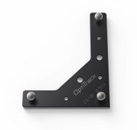
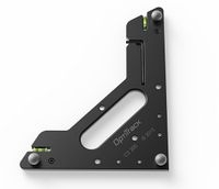
CS-400: Used for general for common mocap applications. Contains knobs for adjusting the balance as well as slots for aligning with a force plate.
Long arm: Positive z
Short arm: Positive x
Vertical offset: 45 mm
Marker size: 19 mm (diameter)
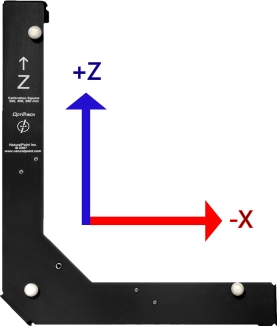
Legacy L-frame square: Legacy calibration square designed before changing to the Right-hand coordinate system.
Long arm: Positive z
Short arm: Negative x
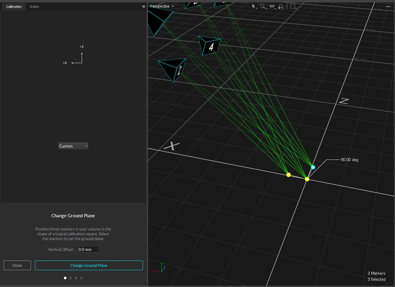
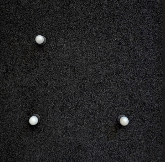
Custom Calibration square: Position three markers in your volume in the shape of a typical calibration square (creating a ~90 degree angle with one arm longer than the other). Then select the markers to set the ground plane.
Long arm: Positive z
Short arm: Negative x
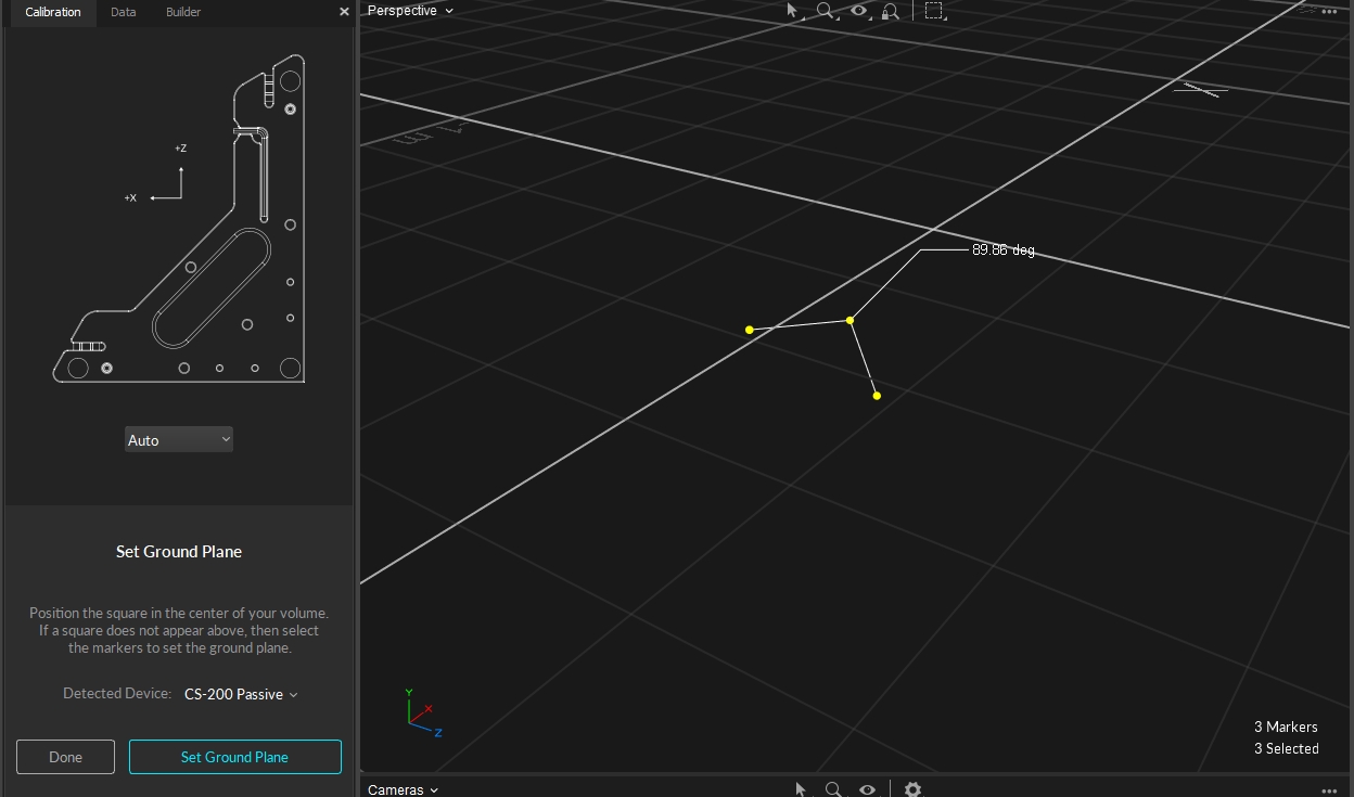
When creating a custom ground plane, you can use Motive to help you move the markers to create approximately 90 degree between the 3 markers. This is of course contingent on how good your calibration is, however, this will still give you a fairly accurate starting point when setting your ground plane.
The Vertical Offset is the distance between the center of the markers on the calibration square and the actual ground and is a required value in setting the global origin.
Motive accounts for the vertical offset when using a standard OptiTrack calibration square, setting the origin at the bottom corner of the calibration square rather than the center of the marker.
When using a custom calibration square, measure the distance between the center of the marker and the lowest tip at the vertex of the calibration square. Enter this value in the Vertical Offset field in the Calibration pane.
The Vertical Offset property can also be used to place the ground plane at a specific elevation. A positive offset value will set the plane below the markers, and a negative value will set the plane above the markers.
For Motive 1.7 or higher, Right-Handed Coordinate System is used as the standard, across internal and exported formats and data streams. As a result, Motive 1.7 now interprets the L-Frame differently than previous releases:
CS-100: Used to define a ground plane in a small, precise motion capture volumes.
Long arm: Positive z
Short arm: Positive x
Vertical offset: 11.5 mm
Marker size: 9.5 mm (diameter)
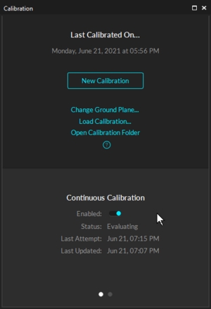
This page provides detailed information on the continuous calibration feature, which can be enabled from the Calibration pane. For additional Continuous Calibration features, please see the Continuous Calibration (Info Pane) page.
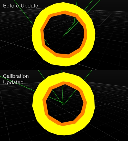
The Continuous Calibration feature ensures your system always remains optimally calibrated, requiring no user intervention to maintain the tracking quality. It uses highly sophisticated algorithms to evaluate the quality of the calibration and the triangulated marker positions. Whenever the tracking accuracy degrades, Motive will automatically detect and update the calibration to provide the most globally optimized tracking system.
Ease of use. This feature provides much easier user experience because the capture volume will not have to be re-calibrated as often, which will save a lot of time. You can simply enable this feature and have Motive maintain the calibration quality.
Optimal tracking quality. Always maintains the best tracking solution for live camera systems. This ensures that your captured sessions retain the highest quality calibration. If the system receives inadequate information from the environment, the calibration with not update and your system never degrades based on sporadic or spurious data. A moderate increase in the number of real optical tracking markers in the volume and an increase in camera overlap improves the likelihood of a higher quality update.
Works with all camera types. Continuous calibration works with all OptiTrack camera models.
For continuous calibration to work as expected, the following criteria must be met:
Live Mode Only. Continuous calibration only works in Live mode.
Markers Must Be Tracked. Continuous calibration looks at tracked reconstructions to assess and update the calibration. Therefore, at least some number of markers must be tracked within the volume.
Majority of Cameras Must See Markers. A majority of cameras in a volume needs to receive some tracking data within a portion of their field of view in order to initiate the calibration process. Because of this, traditional perimeter camera systems typically work the best. Each camera should additionally see at least 4 markers for optimal calibration. If not all the cameras see the markers at the same time, anchor markers will need to be set up to improve the calibration updates.
To enable Continuous Calibration, calibrate the camera system first and enable the Continuous Calibration setting at the bottom of the Calibration pane. Once enabled, Motive continuously monitors the residual values in captured marker reconstructions, and when the updated calibration is better than the existing one, it will get updated automatically. Please note that at least four (default) marker samples must be being tracked in the volume for the continuous calibration to work. You will also be able to monitor the sampling progress and when the calibration has been last updated.
Please see the Continuous Calibration (Info Pane) page for additional features.
Anchor markers further improve the continuous calibration. When properly configured, anchor markers establish a known point-of-reference for continuous calibration updates, especially on systems that consists of multiple sets of cameras that are separated into different tracking areas, by obstructions or walls, without camera view overlap. Anchor markers provide extra assurance that the global origin will not shift during each update, which the continuous calibration feature checks for as well.
Active markers are best to use for anchors due to their unique active IDs, which improve accuracy, remove ambiguity, and enhance continuous calibration all around.
Cameras will always correctly identify an active marker even when no other markers are visible or after an occlusion. This helps the system calibrate more frequently, and to quickly adjust after more significant disturbances.
Anchor markers are critical to maintaining a single calibration throughout a partitioned volume. Active markers ensure that the cameras can correctly identify each anchor marker location.
Active markers allow bumped cameras to update faster and more accurately, and to recover from larger disturbances than passive markers.
For continuous calibration to work, It's important to have multiple markers visible to each camera, dispersed across a significant portion of that camera's field of view. This allows the system to more accurately determine the position and angle of the camera. This is true whether using active or passive markers.
Follow the steps below for setting up the anchor marker in Motive:
Adding Anchor Markers in Motive
First, make sure the entire camera volume is fully calibrated and prepared for marker tracking.
Place any number of markers in the volume to assign them as the anchor markers.
Make sure these markers are securely fixed in place within the volume. It's important that the distances between these markers do not change throughout the continuous calibration updates.
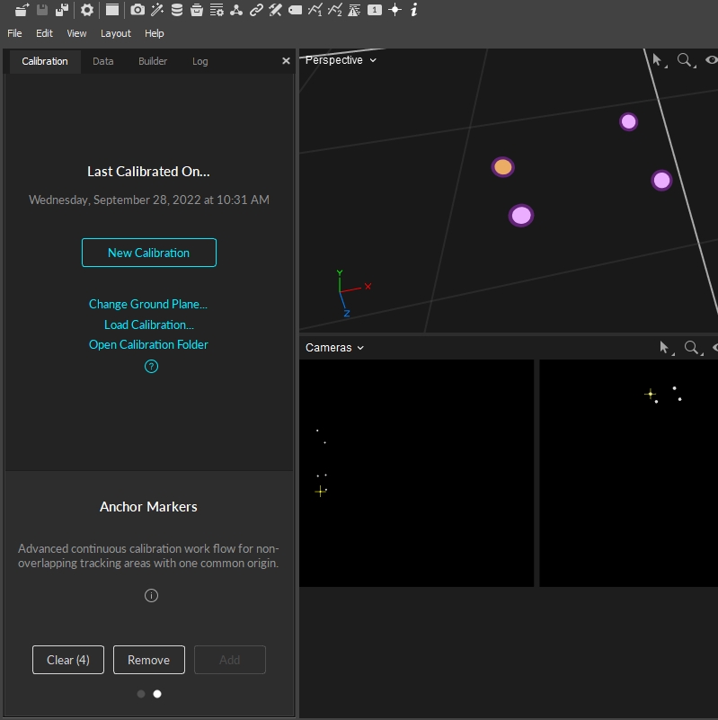
Open the Calibration pane and select the second page at the bottom to access the anchor marker feature.
In the 3D viewport, select the markers that are going to be assigned as anchors.
Click on Add to add the selected markers as anchor markers.
Once markers are added as anchor markers, magenta spheres will appear around the markers indicating the anchors have been set.
Add more anchors as needed, again, it's important that these anchor markers do not move throughout the tracking. Also when the anchor markers need to be reset, whether if the marker was displaced, you can clear the anchor markers and reassign them.
For multi-room setups, it is useful to group cameras into partitions. This allows for Continuous Calibration to run in each individual room without the need for camera view overlap.
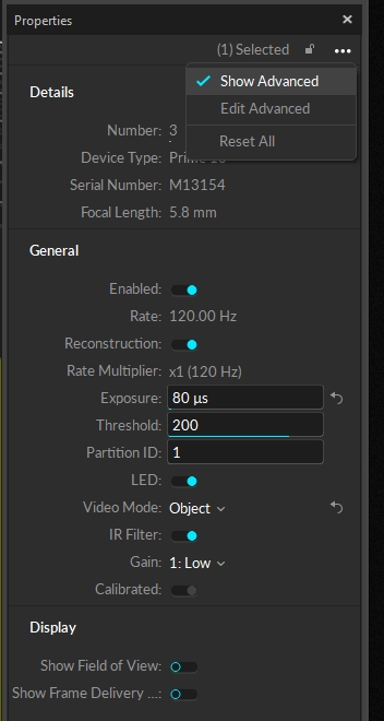
From the Properties pane of a camera you can assign a Partition ID from the advanced settings.
You'll want to assign all the cameras in the same room the same Partition ID. Once assigned these cameras will all contribute to Continuous Calibration for their particular space. This will help ensure the accuracy of Continuous Calibration for each individual space that is a part of the whole system.
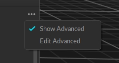
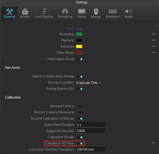
In the event that you need to manually adjust cameras in the 3D view, you can enable Editable in 3D View in General Settings. To access this setting, you'll need to select Show Advanced from the 3-dot more options dropdown at the top. This will populate a Calibration section on this window.
This allows you to use the Gizmo Tools to Translate, Rotate, and Scale cameras to their desired locations.
Within the Info Tab, you'll find additional Continuous Calibration features in order to update your Calibrations in real-time.
Below you'll find the steps for each of these features.
Camera Samples is a visual aid that shows which cameras may need more marker samples or a better distribution of marker samples.
Camera buttons within the Camera Samples section allow you to select the camera. This will also select the camera in the 2D Camera Viewport and Devices pane.
Markers within the field of view that are receiving good tracking rays will appear with a green diamond encompassing the marker.
Markers outside of the FOV will appear standard white.
Markers within FOV that have untracked rays will appear with a red diamond encompassing the marker.
If a camera appears under More Markers:
Select the camera under More Markers.
Navigate to the 2D Viewport and from the top left dropdown select "From Camera 'x'".
This will show the camera's field of view and any markers that it can see within the cyan box.
Add additional markers within the camera's view until the camera button is removed from More Markers.
You may have enough markers so that there are no cameras listed under More Markers, but still see cameras under Better Distribution.
Select a camera listed under Better Distribution.
Navigate to the 2D Viewport and from the top left dropdown select "From Camera 'x'".
This will show the camera's field of view and any markers that it can see within the cyan box.
Add additional markers that are more evenly distributed within the camera's view.
For Better Distribution, oftentimes all you need is a single additional marker separated from another cluster of markers as seen in the image above.
Anchor markers can be set up in Motive to further improve continuous calibration. When properly configured, anchor markers improve continuous calibration updates, especially on systems that consists of multiple sets of cameras that are separated into different tracking areas, by obstructions or walls, without camera view overlap. It also provides extra assurance that the global origin will not shift during each update, although the continuous calibration feature itself already checks for this.
For additional information regarding Anchor markers, please see this page.
The Anchor Markers section allows you to add/remove and import/export Anchor markers. It also shows the mean error under the Distance column for each individual Anchor marker and the overall in the top right in millimeters.
When the icon in the top right is a green circle with a check this denotes that all Anchor markers are visible by at least one camera.
When the icon is a red circle with an x this denotes that at least one Anchor is occluded from all cameras.
For multi-room setups, it is useful to group cameras into partitions. This allows for Continuous Calibration to run in each individual room without the need for camera view overlap.
The Partitions section directly corresponds with Partitions created in the Properties pane for each individual camera. This section displays the status of Continuous Calibration for each partition.
For more information, please see the Partitions section here.
If a Partition or Partitions are not receiving enough marker data to validate or update, they will appear magenta in the table and a red circle with an x icon will appear in the top right of the section.
This is the Partition ID assigned via the camera's Properties pane. By default this value is 1.
Idle - Continuous Calibration is either turned off or there are not enough markers for Continuous Calibration to begin sampling.
Sampling - Continuous Calibration is collecting marker samples.
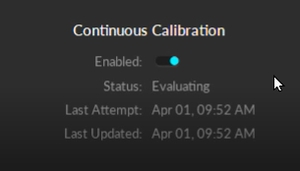
Evaluating - Continuous Calibration is determining if the latest samples are better than the previous and will update if necessary.
Processing - Processing will occur when an update is processing.
Last Validated will update its timestamp to 0h 0m 0s when the samples have been collected and the calibration solution was not deemed to be better than the solution already in place.
Last Updated will update its timestamp to 0h 0m 0s when good samples were collected and the calibration solution was deemed better than the solution in place.
This is the mean ray error for each partition in millimeters. The overall mean ray error will be displayed in the top right corner of the section.
This column denotes the number of Anchor markers that are visible within a partition.
The Partitions settings can be updated to custom values based on an individual user's needs. This ensures that the user is alerted when Continuous Calibration is not validating or updated. When these values are changed the Partitions section rows will turn magenta if they do not meet the standards of Maximum Error and/or Maximum Last Updated.
This setting can be changed to any positive decimal. If the ray error for a Partition exceeds this value, the text in the Partition's row will change to magenta and the icon on the top right of the Partition section will display a red circle with an 'x'.
Maximum Last Updated dictates how long Continuous Calibration can go without an update before the user is alerted (by a magenta text and a red circle with an 'x' icon) that Continuous Calibration has not been updated.
The Bumped Cameras features corrects a camera's position in Motive if it is physically bumped in the real 3D space.
Bumped Cameras needs to be enabled in the Info pane when initializing Continuous Calibration for any fixes to be applied. If it is NOT enabled and a camera is physically displaced, you will need to run a full Calibration to ensure accurate tracking.
Create Anchor markers from the Anchor Markers section or add Active markers.
Enable Bumped Cameras from the Bumped Cameras Settings:
Select Camera Samples for Mode.
Select either Anchor Markers, Active Markers, or Both from Marker Type.
Bumped Cameras is now able to correct physical camera movement without needing a full Calibration.
To see the results of Bumped Cameras steps above you can do the following:
The steps below are not necessary, but something you can do to see Bumped Cameras work in action.
Select the camera's view you intend to physically move in the 2D Camera Viewport.
Make sure Tracked and Untracked Rays are visible from the 'eye' icon in the 2D Camera Viewport.
Physically move the camera so that the markers appear with a red diamond around them (untracked).
Wait a few seconds and notice the camera's view shift to correct in the 2D Camera Viewport.
The red diamonds should now be green.
Disabled - When Mode is set to Disabled, Bumped Camera correction will not apply.
Camera Samples - When Mode is set to Camera Samples, Bumped Camera correction will correct based on the Camera Samples data. If Camera Samples is populated with cameras this will trigger Bumped Cameras to correct any cameras that may have moved. If a camera has NOT moved, this camera will remain idle in the Bumped Camera section until Camera Samples is clear of needed samples or distribution.
Selected Cameras - When Mode is set to Selected Cameras, this will ONLY correct the camera that is selected by the user from either the Devices, 3D or 2D viewport, or Camera Samples.
A camera MUST be selected during a bump for Selected Cameras mode to correct the camera's position.
It must also be de-selected after the camera posistion has been corrected, else the feature will continue to consume high CPU resources and left long term could have a negative effect in quality tracking.
Anchor Markers - ONLY Anchor Markers will be used to collect data for Bumped Cameras to correct a camera's position.
Active Markers - ONLY Active Markers will be used to collect data for Bumped Cameras to correct a camera's position.
Anchor and Active - BOTH Anchor and Active Markers will be used to collect data for Bumped Cameras to correct a camera's position.
If you only wish to have a few cameras corrected you can lower the count of the Max Camera Count. By default this is set to 20.
This page provides detailed instructions on camera system calibration and information about the Calibration pane.
Calibration is essential for high quality optical motion capture systems. During calibration, the system computes the position and orientation of each camera and number of distortions in captured images to construct a 3D capture volume in Motive. This is done by observing 2D images from multiple synchronized cameras and associating the position of known calibration markers from each camera through triangulation.
If there are any changes in a camera setup the system must be recalibrated to accommodate those changes. Additionally, calibration accuracy may naturally deteriorate over time due to ambient factors such as fluctuations in temperature. For this reason, we recommend recalibrating the system periodically.
Prepare and optimize the capture volume for setting up a motion capture system.
Apply masks to ignore existing reflections in the camera view.
Collect calibration samples through the wanding process.
Review the wanding result and apply calibration.
Set the ground plane to complete the system calibration.
Full: Calibrate all the cameras in the volume from scratch, discarding any prior known position of the camera group or lens distortion information. A Full calibration will also take the longest time to run.
Refine: Adjusts slight changes in the calibration of the cameras based on prior calibrations. This will solve faster than a Full calibration. Use this only if the cameras have not moved significantly since they were last calibrated. A Refine calibration will allow minor modifications in camera position and orientation, which can occur naturally from the environment, such as due to mount expansion.
Refinement cannot run if a full calibration has not been completed previously on the selected cameras.
Cameras need to be appropriately placed and configured to fully cover the capture volume.
Each camera must be mounted securely so that it remains stationary during capture.
Motive's camera settings used for calibration should ideally remain unchanged throughout the capture. Re-calibration may be required if there are any significant modifications to the settings that influence the data acquisition, such as camera settings, gain settings, and Filter Switcher settings.
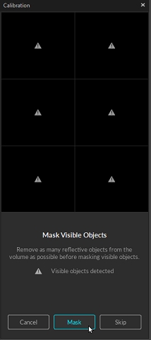
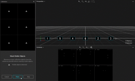
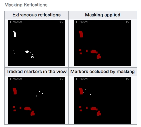
Before performing a system calibration, all extraneous reflections or unnecessary markers should be removed or covered so they are not seen by the cameras. When this isn't possible, extraneous reflections can be ignored by masking them in Motive.
Masks can be applied by clicking Mask in the calibration pane, and it will apply red masks over all of the reflections detected in the 2D camera view. Once masked, the pixels in the masked regions will entirely be filtered out from the data. Please note that Masks get applied additively, so if there are already masks applied in the camera view, clear them out first before applying a new one.
Active Wanding:
Applying masks to camera views is only necessary when using calibration wands with passive markers. Active calibration wands calibrate the capture volume with the LEDs of all the cameras turned off. This method is recommended if the volume has a lot of reflective material that cannot be removed.
Check the corresponding camera view to identify where the reflection is coming from, and if possible, remove it from the capture volume or cover it for the calibration.
In the Calibration pane, click Mask to apply masks over all reflections in the view that cannot be removed or covered, such as other cameras.
Masking from the Cameras Viewport
The wanding process is Motive's core pipeline for collecting calibration samples. A calibration wand with preset markers is waved repeatedly throughout the volume, allowing all cameras to see the calibration markers and capture the sample data points from which Motive will compute their respective position and orientation in the 3D space.
For best results, the following requirements should be met:
At least two cameras must see all three of the calibration markers simultaneously.
Cameras should see only calibration markers. If any other reflection or noise is detected during wanding the sample will not be collected and may affect the calibration results negatively. For this reason, the person doing the wanding should not be wearing anything reflective.
The markers on the calibration wand must be in good quality. If the marker surface is damaged or scuffed, the system may struggle to collect wanding samples.
There are different types of calibration wands suited for different capture applications. In all cases, Motive recognizes the asymmetrical layout of the markers as a wand and applies the dimensions of the wand selected at the beginning of the wanding process in calculating the calibration.
Unless specified otherwise, the wands use retro-reflective markers placed in a line at specific distances. For optimal results, it is important to keep the calibration wand markers untouched and undistorted.
Calibration Wands
CW-500: The CW-500 calibration wand has a wand-width of 500mm when the markers are placed in configuration A. This wand is suitable for calibrating a large size capture volume because the markers are spaced farther apart, allowing the cameras to easily capture individual markers even at long distances.
CW-500 Active: With the same dimensions as the CW-500, the active wand is recommended for capture volumes that have a large amount of reflective material that cannot be removed. This wand calibrates the volume while the LEDs of all mounted cameras are turned off.
CW-250: The CW-250 calibration wand has a wand-width of 250mm. This wand is suitable for calibrating small to medium size volumes. Its narrower wand-width allows cameras in a smaller volume to easily capture all three calibration markers within the same frame. Note that a CW-500 wand can also be used like CW-250 wand if the markers are positioned in configuration B.
CWM-125 / CWM-250: Both CWM-125 and CWM-250 wands are designed for calibrating systems for precision capture applications. The accuracy of the calibrated wand width is the most precise and reliable on these wands, making them more suitable for precision capture in a small volume capture application.
To start calibrating inside the volume, cover one of the markers and expose it wherever you wish to start wanding. When at least two cameras detect all three markers and no other reflections in the volume, Motive will recognize the wand and will start collecting samples.
Confirm that masking was successful, and the volume is free of extraneous reflections. Return to the masking steps if necessary to mask any items that cannot be removed or covered.
To complete a full calibration, deselect any cameras that were selected during the previous steps so that no cameras are selected.
Set the Calibration Type. If you are calibrating a new capture volume, choose Full Calibration.
Under the Wand settings, specify the wand type you will use. Selecting the wrong wand type may result in scaling issues in Motive.
Double check the calibration setting. Once confirmed, press Start Wanding to start collecting wanding sample.
Bring your calibration wand into the capture volume and wave the wand gently across the entire volume. Slowly draw figure-eights repetitively with the wand to collect samples at varying orientations while covering as much space as possible for sufficient sampling.
Wanding trails will show in color in the 2D view for each camera. As you wand, consult the Cameras Viewport to evaluate individual camera coverage. Each camera should be thoroughly covered with wand samples (see image, below). If there are any large gaps, focus wanding on those areas to increase coverage.
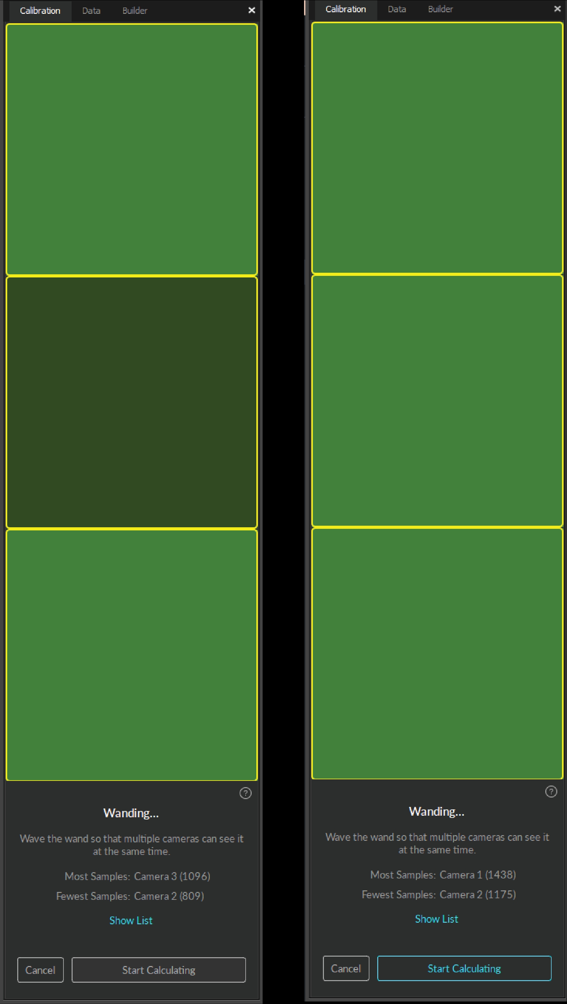
The Calibration pane will display a table of the wanding status to monitor the progress. For best results, wand evenly and comprehensively throughout the volume, covering both low and high elevations.
Continue wanding until the camera squares in the Calibration pane turn from dark green (insufficient number of samples) to light green (sufficient number of samples). Once all the squares have turned light green the Start Calculating button will become active.
Press Start Calculating in the Calibration Pane. Generally, 1,000-4,000 samples per camera are enough. Samples above this threshold are unnecessary and can be detrimental to a calibration's accuracy.
Wanding Tips
Avoid waving the wand too fast. This may introduce bad samples.
Avoid wearing reflective clothing or accessories while wanding. This can introduce extraneous samples which can negatively affect the calibration result.
Try not to collect samples beyond 10,000. Extra samples could negatively affect the calibration.
Try to collect wanding samples covering different areas of each camera's view. The status indicator on Prime cameras can be used to monitor the sample coverage on individual cameras.
Although it is beneficial to collect samples all over the volume, it is sometimes useful to collect more samples in the vicinity of the target regions where more tracking is needed. By doing so, calibration results will have a better accuracy in the specific region.
Marker Labeling Mode
When performing calibration wanding, leave the Marker Labeling Mode at the default setting of Passive Markers Only. This setting is located in Application Settings → Live-Reconstruction tab → Marker Labeling Mode. There are known problems with wanding in one of the active marker labeling modes. This applies for both passive marker calibration wands and IR LED wands.
For Prime series cameras, the LED indicator ring displays the status of the wanding process.
When wanding is initiated, the LED ring turns dark.
When a camera detects all three markers on the calibration wand, part of the LED ring will glow blue to indicate that the camera is collecting samples. The location of the blue light will indicate the wand position in the respective camera view.
As calibration samples are collected by each camera, all the lights in the ring will turn green to indicate enough samples have been collected.
Cameras that do not have enough samples will begin to glow white as other cameras reach the minimum threshold to begin calibration. Check the 2D view to see where additional samples are needed.
When all of the cameras emit a bright green light to indicate enough samples have been collected, the Start Calculating button will become active.
Pess Start Calculating to calibrate. The length of time needed to calculate the calibration varies based on the number of cameras included in the system and the number of collected samples.
As Motive starts calculating, blue wanding paths will display in the view panes, and the Calibration pane will update with the calibration result from each camera.
Click Show List to see the errors for each camera.
Tip: Select a Take in the Data pane to see its related calibration results in the Properties pane. This information is available only for Takes recorded in Motive 1.10 and above.
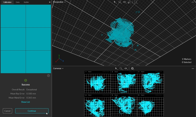
When the calculation is done the results will display in the Calibration pane.
The result is determined by the mean error, resulting in the following ratings: Poor, Fair, Good, Great, Excellent, and Exceptional.
If the results are acceptable, press Continue to apply the calibration. If not, press Cancel and repeat the wanding process.
In general, if the results are anything less than Excellent, we recommend you adjust the camera settings and/or wanding techniques and try again.
Mean Ray Error
The Mean Ray Error reports a mean error value on how closely the tracked rays from each camera converged onto a 3D point with a given calibration. This represents the preciseness of the calculated 3D points during wanding. Acceptable values will vary depending on the size of the volume and the camera count.
Mean Wand Error
The Mean Wand Error reports a mean error value of the detected wand length compared to the expected wand length throughout the wanding process.
The final step of the calibration process is setting the ground plane and origin for the coordinate system in Motive. This is done using a Calibration Square.
Place the calibration square in the volume where you want the origin to be located, and the ground plane to be leveled.
If using a standard OptiTrack calibration square, Motive will recognize it in the volume and display it as the detected device in the Calibration pane.
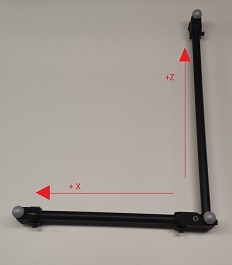
Align the calibration square so that it references the desired axis orientation. Motive recognizes the longer leg on the calibration square as the positive z axis, and the shorter leg as the positive x axis. The positive y axis will automatically be directed upward in a right-hand coordinate system.
Use the level indicator on the calibration square to ensure the orientation is horizontal to the ground. If any adjustment is needed, rotate the nob beneath the markers to adjust the balance of the calibration square.
Once the calibration square is properly placed and detected by the Calibration pane, click Set Ground Plane. You may need to manually select the markers on the ground plane if Motive fails to auto-detect the ground plane.
If needed, the ground plane can be adjusted later.
A custom calibration square can also be used to define the ground plane. All it takes to make a custom square is three markers that form a right-angle with one arm longer than the other, like the shape of the calibration square.
To use a custom calibration square, select Custom in the drop-down menu, enter the correct vertical offset and select the square's markers in the 3D Viewport before setting the ground plane.
The Vertical Offset is the distance between the center of the markers on the calibration square and the actual ground and is a required value in setting the global origin.
Motive accounts for the vertical offset when using a standard OptiTrack calibration square, setting the origin at the bottom corner of the calibration square rather than the center of the marker.
When using a custom calibration square, measure the distance between the center of the marker and the lowest tip at the vertex of the calibration square. Enter this value in the Vertical Offset field in the Calibration pane.
The Vertical Offset property can also be used to place the ground plane at a specific elevation. A positive offset value will set the plane below the markers, and a negative value will set the plane above the markers.
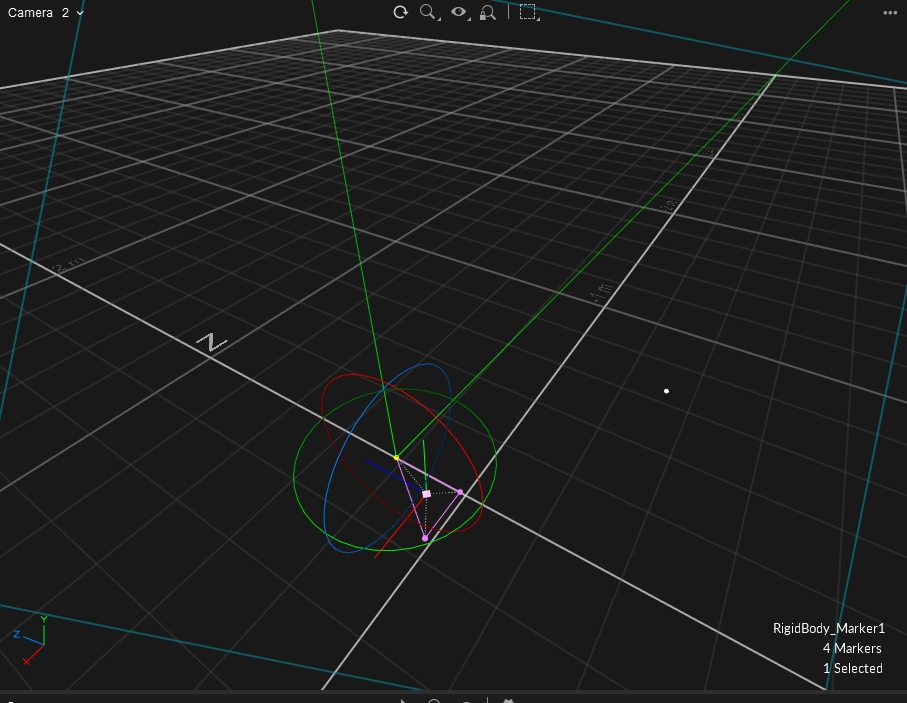
To have the most control of the location of of the global origin, including placing it at the location of a marker, we recommend setting the origin to the pivot point of a rigid body.
Create the Rigid Body.
Align the Rigid Body's pivot point to the location you would like to set as the global origin (0,0,0). To align the pivot point to a specific marker, shift-select the marker and the pivot point. From the Builder pane, click the Modify tab and select Align to...Marker.
Select the Rigid Body in the Assets pane before proceeding to set the ground plane.
In the Calibration pane, select Rigid Body for the Ground Plane. Motive will set the origin to the selected Rigid Body's pivot point.
The Ground Plane Refinement feature improves the leveling of the coordinate plane. This is useful when establishing a ground plane for a large volume, because the surface may not be perfectly uniform throughout the plane.
To use this feature, place several markers with a known radius on the ground, and adjust the vertical offset value to the corresponding radius. Select these markers in Motive and press Refine Ground Plane. This will adjust the leveling of the plane using the position data from each marker.
To adjust the position and orientation of the global origin after the capture has been taken, use the capture volume translation and rotation tool.
To apply these changes to recorded Takes, you will need to reconstruct the 3D data from the recorded 2D data after the modification has been applied.
To rescale the volume, place two markers a known distance apart. Enter the distance, select the two markers in the 3D Viewport, and click Scale Volume.
Calibration files are used to preserve calibration results. The information from the calibration is exported or imported via the CAL file format. Calibration files eliminate the effort of calibrating the system every time you open Motive. Calibration files are automatically saved into the default folders after each calibration. In general, we recommend exporting the calibration before each capture session. By default, Motive loads the last calibration file that was created. This can be changed via the Application Settings.
Note: Whenever there is a change to the system setup (e.g. cameras moved) these calibration files will no longer be relevant and the system will need to be recalibrated.
The continuous calibration feature continuously monitors and refines the camera calibration to its best quality. When enabled, minor distortions to the camera system setup can be adjusted automatically without wanding the volume again. In other words, you can calibrate a camera system once and no longer worry about external distortions such as vibrations, thermal expansion on camera mounts, or small displacements on the cameras. For detailed information, read the Continuous Calibration page.
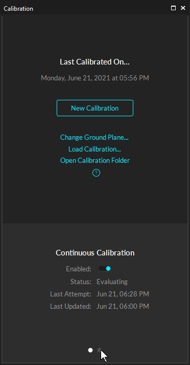
Enabling/Disabling Continuous Calibration
Continuous calibration is enabled from the Calibration Pane once a system has been calibrated. It will also show when the continuous calibration last updated and its current status.
When capturing throughout a whole day, temperature fluctuations may degrade calibration quality and create the need to recalibrate the capture volume at different times of the day. However, repeating the entire calibration process can be tedious and time-consuming especially for a system with a large number of cameras.
Instead of repeating an entire full calibration, you can record Takes while wanding and takes with the calibration square in the volume and use those takes to re-calibrate in the post-processing. This saves calibration calculation time on the capture day because you can apply the calibration from the recorded wanding take in the post-processing instead. Offline calibration allows time to inspect the collected capture data, re-calibrating from a recorded Take only when signs of degraded calibration quality are seen in the captures.
Capture wanding and ground plane Takes. At different times of the day, record wanding Takes that resemble the calibration wanding process. Also record corresponding ground plane Takes with the calibration square set in the volume to define the ground plane.
Whenever a system is calibrated, Motive saves two Calibration (*.cal) files, one of the Wanding and one of the Ground Plane. These files can be reloaded as needed and can also be used to complete an offline calibration.
Open the Take to be recalibrated.
From the Calibration pane, click Load Calibration...
Browse to and select the wanding Take that was captured around the same time as the Take to be recalibrated.
From the Calibration pane, click New Calibration.
In Edit mode, click Start Wanding. Motive will import the wanding from the Take file selected in step 3 and display the results.
Click the Start Calculating button.
(Optional) Export the calibration results by selecting Export Camera Calibration from the File menu. The results will be saved as s .cal file.
Click Apply Results to accept the calibration.
Motive will move to the next step in the calibration process, setting the ground plane. If the ground plane is in a separate Take, then click Done and proceed to step 10. If the ground plane is in the calibration Take already loaded, then move to step 13.
From the Calibration pane, click Load Calibration...
Browse to and select the Ground Plane Take that was captured around the same time as the Take to be recalibrated.
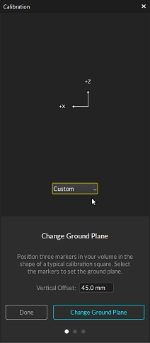
From the Calibration pane, click Change Ground Plane.
Select Custom for the ground plane type, enter the vertical offset distance, select the three markers of the ground plane from the 3D Viewport, then click Change Ground Plane.
Motive will display a warning that any 3D data in the take will need to be reconstructed and auto-labeled. Click Continue to proceed.
Partial calibration updates the calibration for selected cameras in a system by updating their position relative to the already calibrated cameras. Use this feature:
In a high camera count systems where only a few cameras need to be adjusted.
To recalibrate the volume without resetting the ground plane. Motive will retain the position of the ground plane from the unselected cameras.
To add new cameras into a volume that has already been calibrated.
If Continuous Calibration is not enabled and a camera is bumped, use Partial Calibration to adjust the camera that is now out of place.
Select the camera(s) to be recalibrated in the Cameras Viewport.
Open the Calibration Pane and select New Calibration.
Select the Calibration Type. In most cases you will want to set this to Full, such as when adding new cameras to a volume or adjusting several cameras. When the camera moved slightly, Refine works as well.
Specify the wand type.
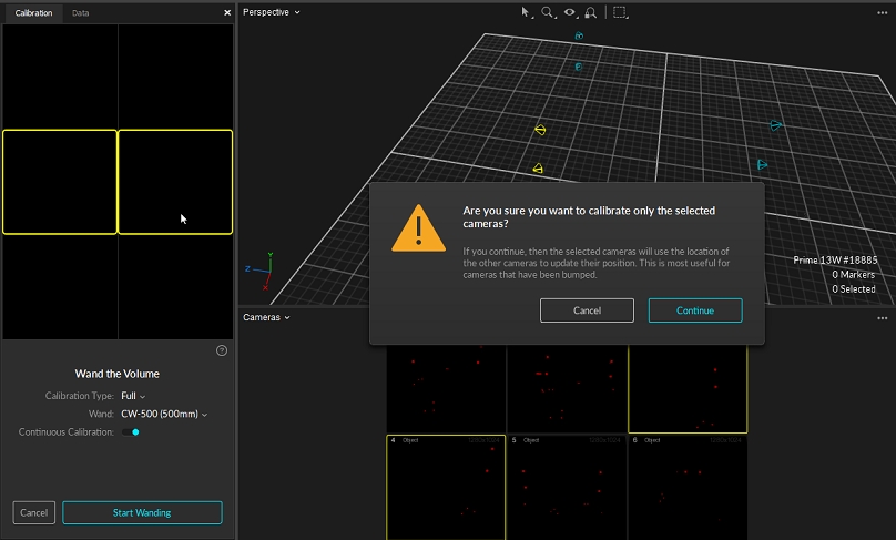
From the Calibration Pane, click Start Wanding. A warning message will ask you to confirm that only the selected cameras will be calibrated. Click continue.
Wand in front of the selected cameras and at least one unselected camera. This will allow Motive to align the cameras being calibrated with the rest of the cameras in the system.
When you have collected sufficient wand samples, click Calculate.
The Calibration Pane will display the results. Repeat steps 2-7 until the results are Excellent or Exceptional.
Click Apply. The selected cameras will now be calibrated to the rest of the cameras in the system.
Notes:
This feature requires the unselected cameras to be in a good calibration state. If the unselected cameras are out of calibration, using this feature will return bad calibration results.
Partial calibration does not update the calibration of the unselected cameras. However, the calibration report that Motive provides does include all cameras that received samples, selected or unselected.
Cameras can be modified using the gizmo tool if the Settings Window > General > Calibration > "Editable in 3D View" property is enabled. Without this property turned on the gizmo tool will not activate when a camera is selected to avoid accidentally changing a calibration. The process for using the gizmo tool to fix a misaligned camera is as follows:
Select the camera you wish to fix, then view from that camera (Hotkey: 3).
Select either the Translate or Rotate gizmo tool (Hotkey: W or E).
Use the red diamond visual to align the unlabeled rays roughly onto their associated markers.
Right click and choose Correct Camera Position/Orientation. This will perform a calculation to place the camera more accurately.
Turn on Continuous Calibration if not already done. Continuous calibration should finish aligning the camera into the correct location.
The OptiTrack motion capture system is designed to track retro-reflective markers. However, active LED markers can also be tracked with appropriate customization. If you wish to use Active LED markers for capture, the system will ideally need to be calibrated using an active LED wand. Please contact us for more details regarding Active LED tracking.
Motive opens the calibration layout view by default, containing the necessary panes for the calibration process. This layout can also be accessed from the calibration layout button in the top-right corner, or by using the Ctrl+1 hotkey.
The Calibration pane will guide you through the calibration process. This pane can be accessed by clicking on the icon on the toolbar or by entering the calibration layout from the top-right corner . For a new system calibration, click the New Calibration button and Motive will walk you through the steps.
The default grid size for the 3D Viewport is 6 square meters. To change this to match the size of the capture volume, click the Settings button. On the Views / 3D tab, adjust the values for the Grid Width and Grid Length as needed.
When the cameras detect reflections in their view, it will be indicated with a warning sign to alert which cameras are seeing reflections; for Prime series cameras, the indicator LED ring will also light up in white.
The calibration pane will display a warning for any cameras that see reflections or noise in their view.
Masks can also be applied from the Cameras Viewport if needed. From the Cameras view, click the gear icon on the toolbar to see masking options. You can also click on the icon to switch to different modes to manually apply or erase masks.
On the main Calibration pane, Click Change Ground Plane... for additional tools to further refine your calibration. Use the page selector at the bottom of the pane to access the various page.