Loading...
Loading...
Loading...
Loading...
Loading...
Loading...
Loading...
Loading...
Loading...
Loading...
Loading...
Loading...
Loading...
Loading...
Loading...
Loading...
Loading...
Loading...
Loading...
Loading...
Loading...
Loading...
Loading...
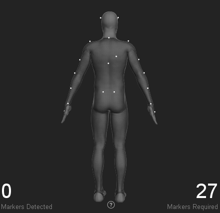
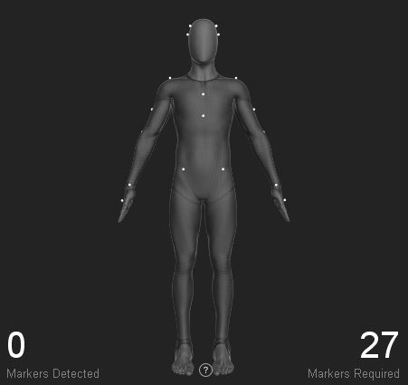
LAH RAH
Head
Left Anterior Head Right Anterior Head
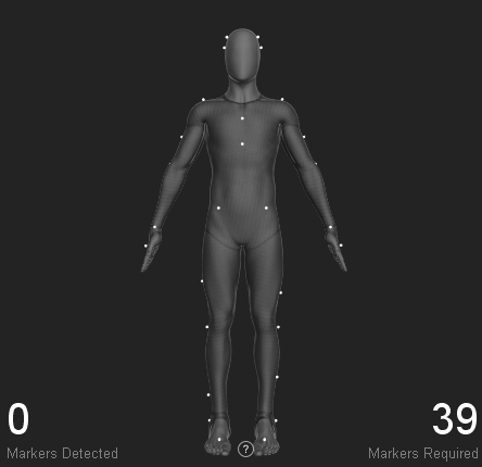
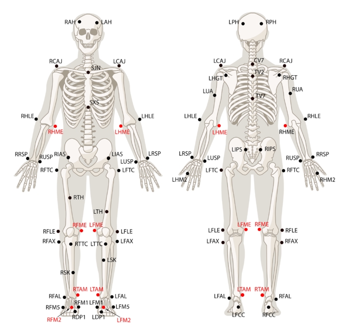
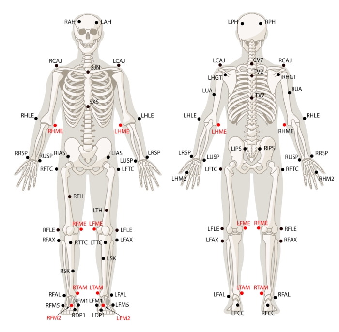
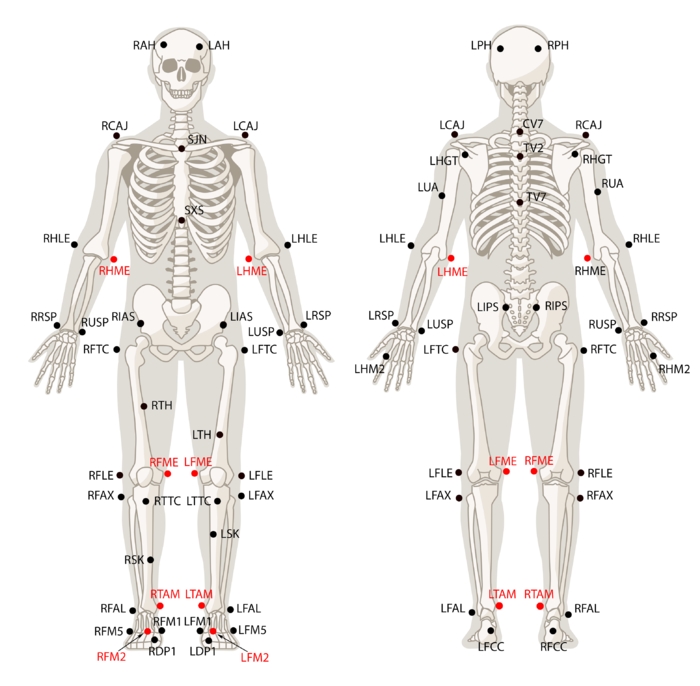
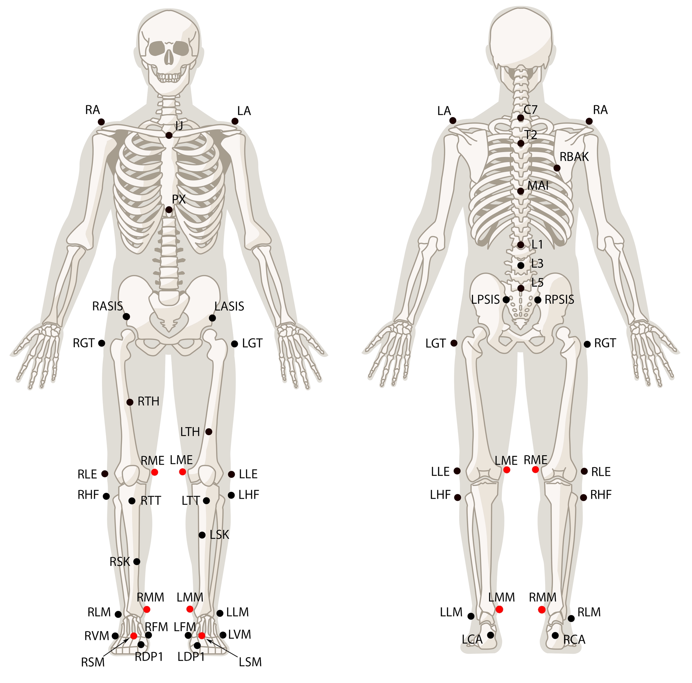
Place the markers on the left and right side of the fore head. The respective location is shown in the Skeleton figure.
LPH RPH
Head
Left Posterior head Right Posterior head
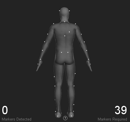
Place the markers on the left and right side of the head about 2 cm behind the ear. The respective location is shown in the Skeleton figure.
Thorax
Sternum Jugular Notch
Top most section of the sternum. Place the marker on the center of the two clavicle bones.
Thorax
Sternum Xiphoid Process
Lowest section of the sternum. Place the marker 1-2 cm above where bottom of the two rib cages conjoin.
Thorax
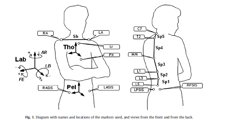
Cervical Spine Vertebra 7
The 7th cervical spine vertebra is the largest vertebra located at the most inferior region of the neck. This section usually protrudes to the posterior side and can be palpated.
Thorax
Thoracic Spine Vertebra 2
The second thoracic spine vertebra is located three spine levels below the C7 vertebra. Which is located approximately at same height with shoulder joint markers.
Thorax
Thoracic Spine Vertebra 7
Usually located at the center of the thoracic spinal column.
Pelvis
Left Iliac Anterior Spine Right Iliac Anterior Spine
Place the marker on the protruding bones located on the left and right side of the pelvis front.
Pelvis
Left Iliac Posterior Spine Right Iliac Posterior Spine
Place each marker on the two dimples which can be palpated near the spine right above the hips.
Note that the waist markers are the key markers in modeling the pelvis bone, which is the major segment governing the other subsequent Skeleton segments.
Thorax
Left Clavicle-Acromion Joint Right Clavicle-Acromion Joint
Ask the subject to stretch both arms towards the side (T-pose), then palpate top of each shoulder for the protruding bone. The prominence is usually located at the end of the corresponding clavicle bone just before where the upper arm starts.
LHLE RHLE
Upper Arm
Left Humerus Lateral Epicondyle Right Humerus Lateral Epicondyle
Placed the markers on the lateral side of the elbow axis. Flex and extend the arm few times to find where elbow axis is located.
LUA RUA
Upper Arm
Left Upper Arm Right Upper Arm
Ask the subject to stand in T-pose while placing the marker. Palpate to find the groove between the triceps muscles where skin movements are relatively minimal.
LHM2 RHM2
Hand
Left Hand Second metacarpal Right Hand Second metacarpal
Place the marker slight below the knuckle of the index finger.
LUSP RUSP
Hand
Left Ulna Styloid Process Right Ulna Styloid Process
Place the marker on the lateral side of the wrist axis.
LRSP RRSP
Hand
Left Radius Styloid Process Right Radius Styloid Process
Place the marker on the medial side of the wrist axis.
For best results, place the three hand markers so the created shape is asymmetrical (avoid isosceles shape) and unique from the marker arrangements on the other hand. Since the wrist markers have defined placement — along the wrist axis — introduce small amount of positional offset to the LHM2 and RHM2 markers.
Upper Leg
Left Femur Lateral Epicondyle Right Femur Lateral Epicondyle
Place the marker on the lateral prominence of the knee joint axis. More specifically, the marker should be placed on the femur epicondyle. You may need to ask the subject to flex and extend the knee few times to locate the axis.
LTH RTH
Upper Leg
Left Thigh Right Thigh
Place the markers at the front center of the thigh near the midline. This marker is placed for distinguishing left and right side of the Skeleton. For best results, slightly offset the height of right and left marker to introduce an asymmetry.
LSK RSK
Upper Leg
Left Superior Knee Right Superior Knee
Place the markers on the shin bone near the midline of the lower leg. This marker is placed for distinguishing left and right side of the Skeleton. For best results, slightly offset the height of right and left marker to introduce an asymmetry.
Lower Leg
Left Tibial Tubercle Right Tibial Tubercle
Place the marker about 2-3 cm below the knee cap bone. This marker should be placed on the most anterior point of the tibial tuberosity.
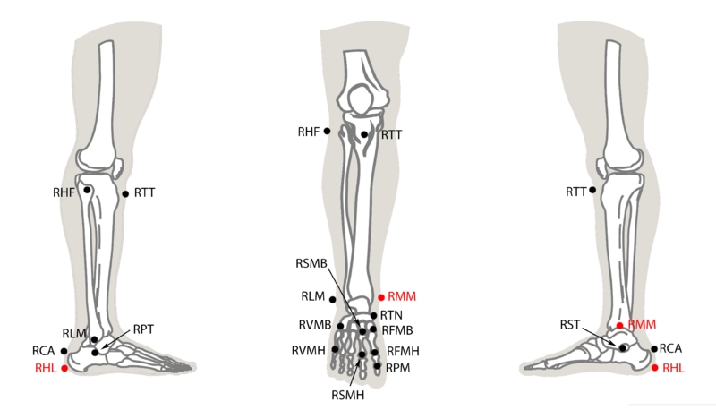
The joint center of the knee and the ankle is modeled at the midpoint of the lateral and medial joint markers (FLE/FME and FAL/TAM). Assuming that center of the femoral head aligns with the center of the acetabulum, its virtual location is modeled using markers on the pelvis segment (posterior and anterior iliac spine markers). The lower extremity segments are modeled along these three virtual locations.
Lower Leg/Foot
Left Fibula Ankle Lateral Right Fibula Ankle Lateral
Place the maker on the lateral side of the ankle axis; on the lateral prominence of the lateral malleolus bone.
Foot
Left Foot Second Metatarsal Right Foot Second Metatarsal
Place the marker on the dorsal aspect of the second metatarsal bone.
Foot
Left Foot Calcaneus Right Foot Calcaneus
Place the marker on center of the heel, where the Achilles tendon attaches to the calcneous bone.
Leardini, A., Biagi, F., Merlo, A., Belvedere, C., Benedetti, M.G., 2011. Multi-segment trunk kinematics during locomotion and elementary exercises. Clin. Biomech. 26, 562-571.
Leardini, A., Sawacha, Z., Paolini, G., Ingrosso, S., Nativo, R., Benedetti, M.G., 2007. A new anatomically based protocol for gait analysis in children. Gait Posture 26. 560-571.
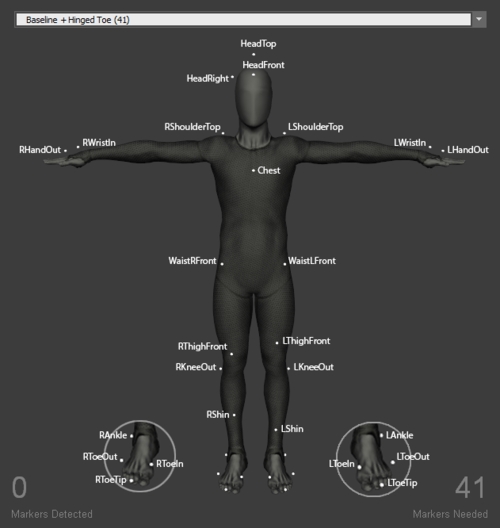
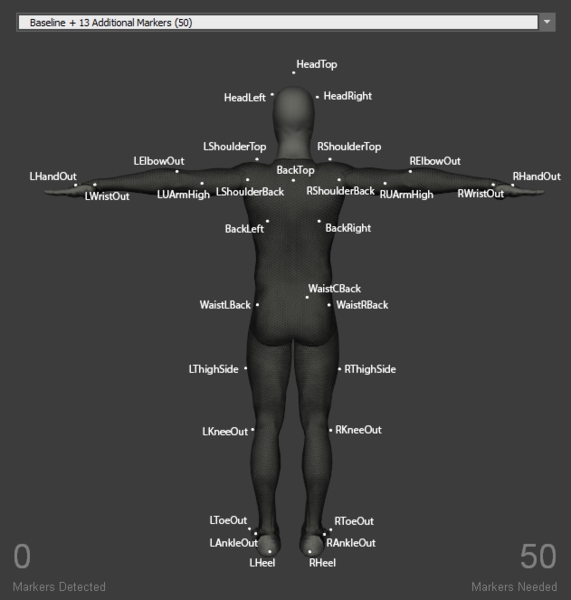
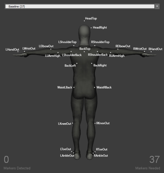
HeadTop
Head
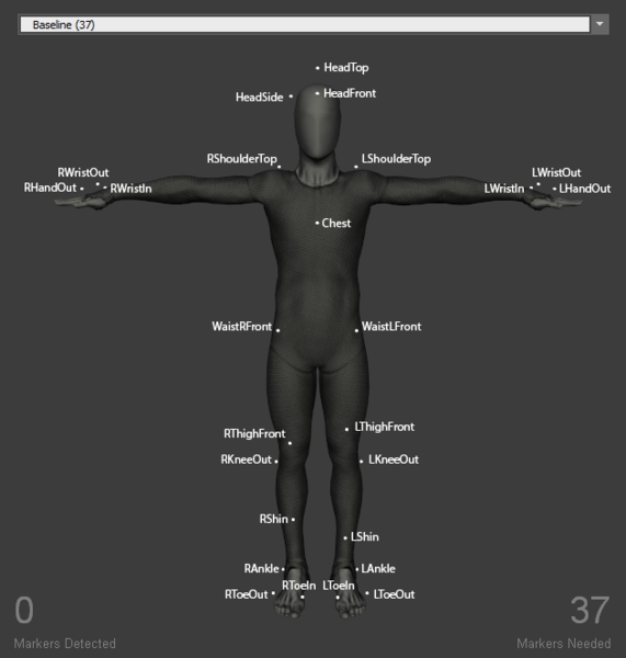
Place the marker on the head tip.
HeadFront
Head
Place the marker at the center of the forehead.
HeadSide
Head
Place the marker on the either side of the head, slightly above the ear. When capturing multiple actors with similar proportions, place the marker on opposite side for clearer distinction.
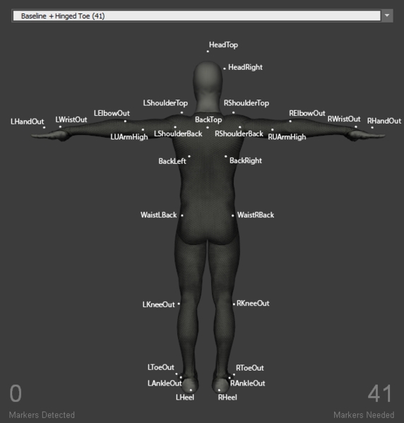
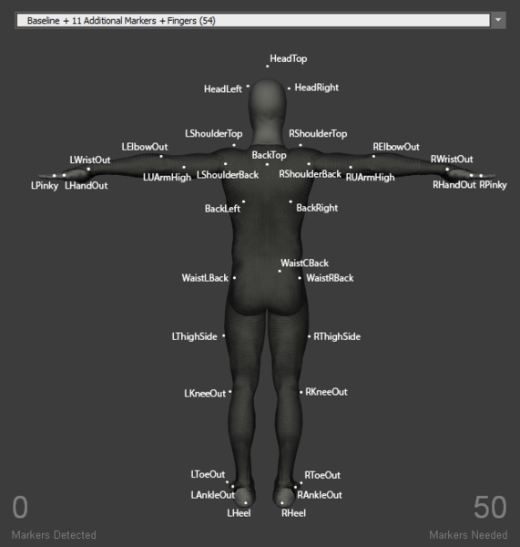
BackTop
Torso
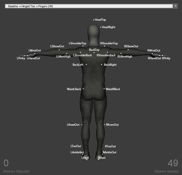
Place the marker on the spine right below the neck. For best results, LUArmHigh-LShoulderBack-BackTop-RshoulderBack-RUArmHigh markers should align roughly in a straight line when the actor is in T-pose. Also, note that this marker must be placed at an elevation higher than the chest marker for the torso segment to be tracked properly.
Chest
Torso
Place the marker at the center of the sternum, about 5 cm below where the neck starts.
BackLeft BackRight
Torso
These two markers are located symmetrically on each side of the back, slightly below the lowest end of the shoulder blade (scapular bone).
Note that the waist markers are the key markers in modeling the pelvis bone, which is the major segment governing the other subsequent Skeleton segments. For best results, avoid placing the waist markers in a rectangle shape. When tracking multiple actors with similar proportions, introduce an offset to one of the WaistBack marker, or the WaistCMarker (included only with the 13 additional Marker Set), to create an asymmetrical arrangements.
WaistLFront WaistRFront
Pelvis
Placed the marker on the protruding bone located on the front of the pelvis (left/right anterior iliac spine bone). The prominence can be palpated from left and right side of the waist.
WaistLBack WaistRBack
Pelvis
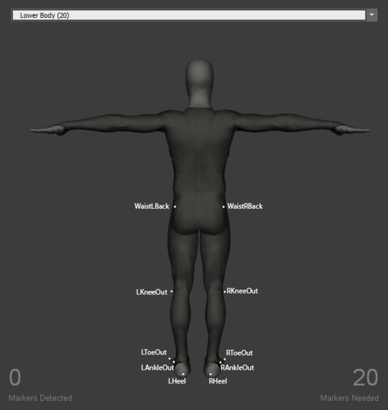
Place the WaistLBack and WaistRBack markers above left/right hip; about 10 cm above the hip joint.
When placing the shoulder markers, ask the actor to stand in the T-pose in order to place the markers on accurate locations. It could also be helpful to ask the actor to do few rounds of arm abduction and adduction to palpate for the shoulder axis. These markers determine the width of the shoulder and respective relationship with the upper arm segment.
LShoulderBack RShoulderBack
Shoulder
Place the marker on the shoulder joint (glenohumeral joint) on the back.
LShoulderTop RShoulderTop
Shoulder
Place the marker at the top of each shoulder where you can palpate the protruding bone, which is usually located just before where the upper arm start when in T-pose. More specifically, the prominence is on the distal end of the clavicle bone (acromioclavicular joint).
LElbowOut RElbowOut
Upper Arm
Place the marker on the lateral side of the elbow joint, slightly towards the upper arm. More specifically, on the lateral epicondyle of the distal end of the humerus. Ask the actor to flex and extend the arm few times to confirm that markers are placed along the elbow axis and maintain stationary throughout the range of motion cycles.
LUArmHigh RUArmHigh
Upper Arm
Place the marker on the back of the upper arm near the groove between the triceps. For best results, LUArmHigh, LShoulderBack, BackTop, RshoulderNack, and RUArmHigh should align roughly in a straight line when in T-pose.
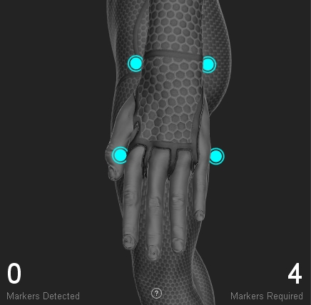
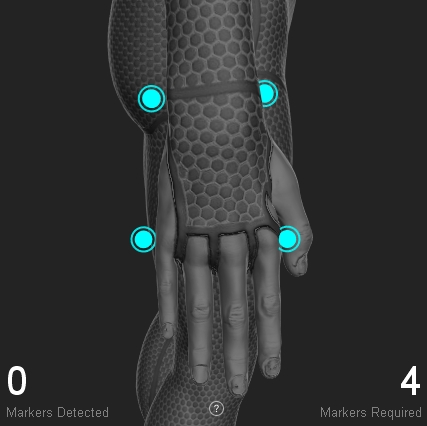
For best results, place the hand markers so that the shape of the marker arrangement is asymmetrical itself and also unique to the shape on the other hand. Since the wrist marker placement is fixed along the wrist axis, offset the HandOut or the HandIn markers to create the unique arrangements. For more robust and simple tracking, hand rigid-bodies can be attached on the hand to replace the markers and guarantee the asymmetrical and non-deforming marker placement.
LWristOut RWristOut
Fore Arm / Hand
Place the marker on the outside (lateral side) of the wrist axis. (distal end of the radius bone). Note that the wrist axis is not always located on the protruding bone but 1-2 cm more towards the hand.
LWristIn RWristIn
Fore Arm / Hand
Place the marker on the inner prominence (medial side) of the wrist axis (distal end of the ulnar bone).
LHandOut RHandOut
Hand
Place the marker slightly below the pinky knuckle. More specifically, between distal end of the fifth and fourth metacarpal bones.
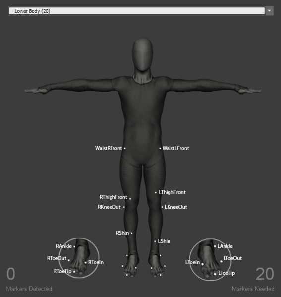
LThighFront RThighFront
Upper Leg
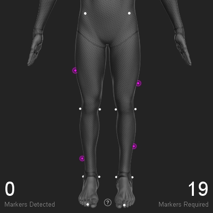
Place the marker on the front side of the thigh, along the midline. For best results, slightly offset the height of the left and right markers to introduce the asymmetry.
LKneeOut RKneeOut
Upper Leg
Place the marker on the outer prominence of the knee joint; on the lateral epicondyle of the femur. Palpate the knee for the protruding bone from the upper leg, and place it right on the axis. Ask the actor to flex and extend the knee few times to confirm that the markers are placed along the axis and maintain stationary throughout the range of motion cycles.
LShin RShin
Lower Leg
Place the marker on the shin bone; on the midline of the lower leg. For best results, slightly offset the height of the left and right markers to introduce the asymmetry.
LAnkleOut RAnkleOut
Lower Leg/Foot
Place the marker on the protruding bone outside of the ankle joint; on the lateral end of the malleolus bone.
LToeOut RToeOut
Foot
Place the marker just before the little toe joint; on the distal end of the fifth metatarsal bone.
LToeIn RToeIn
Foot
Place the marker just before the big toe joint; on the distal end of the first metatarsal bone.
Hinged toe Marker Sets create toe segments in the Skeleton. Two additional markers are added to each foot, one on the toe-tip and another on the heel. The hinged toe markers are included in all baseline Marker Sets except for Baseline (37) and Upper Body Marker Sets.
LHeel RHeel
Foot
Place at the center of the heel.
LToeTip RToeTip
Toe
Place the marker on the tip of the second toe; next to the big toe.
HeadTop
Head
Place the marker on the head tip.
HeadFront
Head
Place the marker at the center of the forehead.
HeadSide
Head
Place the marker on the either side of the head, slightly above the ear. When capturing multiple actors with similar proportions, place the marker on opposite side for clearer distinction.
BackTop
Torso
Place the marker on the spine right below the neck. For best results, LUArmHigh-LShoulderBack-BackTop-RshoulderBack-RUArmHigh markers should align roughly in a straight line when the actor is in T-pose. Also, note that this marker must be placed at an elevation higher than the chest marker for the torso segment to be tracked properly.
Chest
Torso
Place the marker at the center of the sternum, about 5 cm below where the neck starts.
BackLeft BackRight
Torso
These two markers are located symmetrically on each side of the back, slightly below the lowest end of the shoulder blade (scapular bone).
Note that the waist markers are the key markers in modeling the pelvis bone, which is the major segment governing the other subsequent Skeleton segments. For best results, avoid placing the waist markers in a rectangle shape. When tracking multiple actors with similar proportions, introduce an offset to one of the WaistBack marker, or the WaistCMarker (included only with the 13 additional Marker Set), to create an asymmetrical arrangements.
WaistLFront WaistRFront
Pelvis
Placed the marker on the protruding bone located on the front of the pelvis (left/right anterior iliac spine bone). The prominence can be palpated from left and right side of the waist.
WaistLBack WaistRBack
Pelvis
Place the WaistLBack and WaistRBack markers above left/right hip; about 10 cm above the hip joint.
When placing the shoulder markers, ask the actor to stand in the T-pose in order to place the markers on accurate locations. It could also be helpful to ask the actor to do few rounds of arm abduction and adduction to palpate for the shoulder axis. These markers determine the width of the shoulder and respective relationship with the upper arm segment.
LShoulderBack RShoulderBack
Shoulder
Place the marker on the shoulder joint (glenohumeral joint) on the back.
LShoulderTop RShoulderTop
Shoulder
Place the marker at the top of each shoulder where you can palpate the protruding bone, which is usually located just before where the upper arm start when in T-pose. More specifically, the prominence is on the distal end of the clavicle bone (acrominoclavicular joint).
LElbowOut RElbowOut
Upper Arm
Place the marker on the lateral side of the elbow joint, slightly towards the upper arm. More specifically, on the lateral epicondyle of the distal end of the humerous. Ask the actor to flex and extend the arm few times to confirm that markers are placed along the elbow axis and maintain stationary throughout the range of motion cycles.
LUArmHigh RUArmHigh
Upper Arm
Place the marker on the back of the upper arm near the groove between the triceps. For best results, LUArmHigh, LShoulderBack, BackTop, RshoulderNack, and RUArmHigh should align roughly in a straight line when in T-pose.
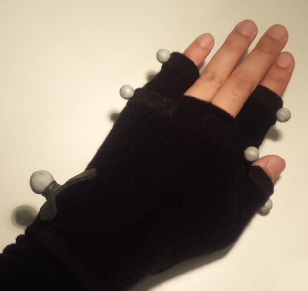
Finger Marker Sets include extra markers on the fingers, and the finger tracking is done by analyzing the kinematics of the hand and estimating the pose of each finger. The WristIn marker is removed and replaced by a forearm marker. Attaching finger markers uses mocap Velcro gloves and hand markers, which can be found from our webstore.
LFArm RFArm
Forearm
Place the marker on the front side of the forearm while in T-pose. For best results, slightly offset the left and right forearm markers to introduce the asymmetry on each side.
LWristOut RWristOut
Fore Arm / Hand
This marker is not included in the finger Marker Sets. Place the marker on the outside (lateral side) of the wrist axis. (distal end of the radius bone). Note that the wrist axis is not always located on the protruding bone but 1-2 cm more towards the hand.
LThumb RThumb
Hand
Place the marker on the side of the thumb joint.
LIndex RIndex
Hand
Place the marker on the side of the index finger joint (proximal interphalangeal joint).
LPinky RPinky
Hand
Place the marker on the side of the pinky finger joint (proximal interphalangeal joint).
LHandIn RHandIn
Hand
Place the marker on the knuckle of the index finger, but slightly towards the side.
LHandOut RHandOut
Hand
Place the marker on the knuckle of the pinky finger, but slightly towards the side.
LThighFront RThighFront
Upper Leg
Place the marker on the front side of the thigh, along the midline. For best results, slightly offset the height of the left and right markers to introduce the asymmetry.
LKneeOut RKneeOut
Upper Leg
Place the marker on the outter prominence of the knee joint; on the lateral epicondyle of the femur. Palpate the knee for the protruding bone from the upper leg, and place it right on the axis. Ask the actor to flex and extend the knee few times to confirm that the markers are placed along the axis and maintain stationary throughout the range of motion cycles.
LShin RShin
Lower Leg
Place the marker on the shin bone; on the midline of the lower leg. For best results, slightly offset the height of the left and right markers to introduce the asymmetry.
LAnkleOut RAnkleOut
Lower Leg/Foot
Place the marker on the protruding bone outside of the ankle joint; on the lateral end of the malleolus bone.
LToeOut RToeOut
Foot
Place the marker just before the little toe joint; on the distal end of the fifth metatarsal bone.
LToeIn RToeIn
Foot
Place the marker just before the big toe joint; on the distal end of the first metatarsal bone.
Hinged toe Marker Sets create toe segments in the Skeleton. Two additional markers are added to each foot, one on the toe-tip and another on the heel. The hinged toe markers are included in all baseline Marker Sets except for Baseline (37) and Upper Body Marker Sets.
LHeel RHeel
Foot
Place at the center of the heel.
LToeTip RToeTip
Toe
Place the marker on the tip of the second toe; next to the big toe.
This Marker Set can be used with Active Tags in conjunction with the Core Marker Set.
The Core + Active Fingers Marker Set has the same placement for the body as the Core Marker Set, however, there are additional Active markers on the hand and fingers.
The Active Finger Markerset uses a total of 10 markers per hand, 8 active with 2 passive markers attached at the wrist.
LWristOut RWristOut
Fore Arm / Hand
Place the marker on the outside (lateral side) of the wrist axis. (distal end of the radius bone). Note that the wrist axis is not always located on the protruding bone but 1-2 cm more towards the hand.
LWristIn RWristIn
Fore Arm / Hand
Place the marker on the inner prominence (medial side) of the wrist axis (distal end of the ulnar bone).
LHandOut RHandOut
Hand
Place the marker slightly below the pinky knuckle. More specifically, between distal end of the fifth and fourth metacarpal bones.
LHandIn RHandIn
Hand
Place the marker slightly below the forefinger knuckle. More specifically, between distal end of the second metacarpal bones.
LThumb RThumb
Finger
Place the marker on the thumb on the 1st metacarpophalangeal joint
LFingers RFingers
Finger
Place markers on the tips of each finger and thumb
Note that the waist markers are the key markers in modeling the pelvis bone, which is the major segment governing the other subsequent Skeleton segments. For best results, avoid placing the waist markers in a rectangle shape. When tracking multiple actors with similar proportions, introduce an offset to one of the WaistBack marker, or the WaistCMarker (included only with the 13 additional Marker Set), to create an asymmetrical arrangements.
WaistLFront WaistRFront
Pelvis
Placed the marker on the protruding bone located on the front of the pelvis (left/right anterior iliac spine bone). The prominence can be palpated from left and right side of the waist.
WaistLBack WaistRBack
Pelvis
Place the WaistLBack and WaistRBack markers above left/right hip; about 10 cm above the hip joint.
BackTop
Torso
Place the marker on the spine right below the neck. For best results, LUArmHigh-LShoulderBack-BackTop-RshoulderBack-RUArmHigh markers should align roughly in a straight line when the actor is in T-pose. Also, note that this marker must be placed at an elevation higher than the chest marker for the torso segment to be tracked properly.
Chest
Torso
Place the marker at the center of the sternum, about 5 cm below where the neck starts.
BackLeft BackRight
Torso
These two markers are located symmetrically on each side of the back, slightly below the lowest end of the shoulder blade (scapular bone).
When placing the shoulder markers, ask the actor to stand in the T-pose in order to place the markers on accurate locations. It could also be helpful to ask the actor to do few rounds of arm abduction and adduction to palpate for the shoulder axis. These markers determine the width of the shoulder and respective relationship with the upper arm segment.
LShoulderBack RShoulderBack
Shoulder
Place the marker on the shoulder joint (glenohumeral joint) on the back.
LShoulderTop RShoulderTop
Shoulder
Place the marker at the top of each shoulder where you can palpate the protruding bone, which is usually located just before where the upper arm start when in T-pose. More specifically, the prominence is on the distal end of the clavicle bone (acrominoclavicular joint).
HeadTop
Head
Place the marker on the head tip.
HeadFront
Head
Place the marker at the center of the forehead.
HeadSide
Head
Place the marker on the either side of the head, slightly above the ear. When capturing multiple actors with similar proportions, place the marker on opposite side for clearer distinction.
LElbowOut RElbowOut
Upper Arm
Place the marker on the lateral side of the elbow joint, slightly towards the upper arm. More specifically, on the lateral epicondyle of the distal end of the humerous. Ask the actor to flex and extend the arm few times to confirm that markers are placed along the elbow axis and maintain stationary throughout the range of motion cycles.
LUArmHigh RUArmHigh
Upper Arm
Place the marker on the back of the upper arm near the groove between the triceps. For best results, LUArmHigh, LShoulderBack, BackTop, RshoulderNack, and RUArmHigh should align roughly in a straight line when in T-pose.
For best results, place the hand markers so that the shape of the marker arrangement is asymmetrical itself and also unique to the shape on the other hand. Since the wrist marker placement is fixed along the wrist axis, offset the HandOut or the HandIn markers to create the unique arrangements. For more robust and simple tracking, hand rigid-bodies can be attached on the hand to replace the markers and guarantee the asymmetrical and non-deforming marker placement.
LWristOut RWristOut
Fore Arm / Hand
Place the marker on the outside (lateral side) of the wrist axis. (distal end of the radius bone). Note that the wrist axis is not always located on the protruding bone but 1-2 cm more towards the hand.
LWristIn RWristIn
Fore Arm / Hand
Place the marker on the inner prominence (medial side) of the wrist axis (distal end of the ulnar bone).
LHandOut RHandOut
Hand
Place the marker slightly below the pinky knuckle. More specifically, between distal end of the fifth and fourth mertacarpal bones.
LAH RAH
Head
Left Anterior Head Right Anterior Head
Place the markers on the left and right side of the fore head. The respective location is shown in the Skeleton figure.
LPH RPH
Head
Left Posterior head Right Posterior head
Place the markers on the left and right side of the head about 2 cm behind the ear. The respective location is shown in the Skeleton figure.
Thorax
Sternum Jugular Notch
Top most section of the sternum. Place the marker on the center of the two clavicle bones.
Thorax
Sternum Xiphoid Process
Lowest section of the sternum. Place the marker 1-2 cm above where bottom of the two rib cages conjoin.
Thorax
Cervical Spine Vertebra 7
The 7th cervical spine vertebra is the largest vertebra located at the most inferior region of the neck. This section usually protrudes to the posterior side and can be palpated.
Thorax
Thoracic Spine Vertebra 2
The second thoracic spine vertebra is located three spine levels below the C7 vertebra. Which is located approximately at same height with shoulder joint markers.
Thorax
Thoracic Spine Vertebra 7
Usually located at the center of the thoracic spinal column.
Pelvis
Left Iliac Anterior Spine Right Iliac Anterior Spine
Place the marker on the protruding bones located on the left and right side of the pelvis front.
Pelvis
Left Iliac Posterior Spine Right Iliac Posterior Spine
Place each marker on the two dimples which can be palpated near the spine right above the hips.
Note that the waist markers are the key markers in modeling the pelvis bone, which is the major segment governing the other subsequent Skeleton segments.
Thorax
Left Clavicle-Acromion Joint Right Clavicle-Acromion Joint
Ask the subject to stretch both arms towards the side (T-pose), then palpate top of each shoulder for the protruding bone. The prominence is usually located at the end of the corresponding clavicle bone just before where the upper arm starts.
LHLE RHLE
Upper Arm
Left Humerus Lateral Epicondyle Right Humerus Lateral Epicondyle
Placed the markers on the lateral side of the elbow axis. Flex and extend the arm few times to find where elbow axis is located.
LUA RUA
Upper Arm
Left Upper Arm Right Upper Arm
Ask the subject to stand in T-pose while placing the marker. Palpate to find the groove between the triceps muscles where skin movements are relatively minimal.
Not depicted in diagram
Forearm
Left Lower Arm Right Lower Arm
Place marker along the Ulna bone along the same line as the LUSP/RUSP marker
LHM2 RHM2
Hand
Left Hand Second metatarsal Right Hand Second metatarsal
Place the marker slight below the knuckle of the index finger.
LUSP RUSP
Hand
Left Ulna Styloid Process Right Ulna Styloid Process
Place the marker on the lateral side of the wrist axis.
LRSP RRSP
Hand
Left Radius Styloid Process Right Radius Styloid Process
Place the marker on the medial side of the wrist axis.
For best results, place the three hand markers so the created shape is asymmetrical (avoid isosceles shape) and unique from the marker arrangements on the other hand. Since the wrist markers have defined placement — along the wrist axis — introduce small amount of positional offset to the LHM2 and RHM2 markers.
Leardini, A., Biagi, F., Merlo, A., Belvedere, C., Benedetti, M.G., 2011. Multi-segment trunk kinematics during locomotion and elementary exercises. Clin. Biomech. 26, 562-571.
Leardini, A., Sawacha, Z., Paolini, G., Ingrosso, S., Nativo, R., Benedetti, M.G., 2007. A new anatomically based protocol for gait analysis in children. Gait Posture 26. 560-571.
HeadTop
Head
Place the marker on the head tip.
HeadFront
Head
Place the marker at the center of the forehead.
HeadLeft / HeadRight
Head
Place markers on each side of the head (left and right), slightly above the ear. For better tracking results, the marker arrangement formed by HeadLeft, HeadRight, and HeadFront should form an asymmetrical arrangement. To achieve this, you can introduce a slight offset to one of the markers placed on the side, either HeadLeft or HeadRight marker.
BackTop
Torso
Place the marker on the spine right below the neck. For best results, LUArmHigh-LShoulderBack-BackTop-RshoulderBack-RUArmHigh markers should align roughly in a straight line when the actor is in T-pose. Also, note that this marker must be placed at an elevation higher than the chest marker for the torso segment to be tracked properly.
Chest
Torso
Place the marker at the center of the sternum, about 5 cm below where the neck starts.
BackLeft BackRight
Torso
These two markers are located symmetrically on each side of the back, slightly below the lowest end of the shoulder blade (scapular bone).
When placing the shoulder markers, ask the actor to stand in the T-pose in order to place the markers on accurate locations. It could also be helpful to ask the actor to do few rounds of arm abduction and adduction to palpate for the shoulder axis. These markers determine the width of the shoulder and respective relationship with the upper arm segment.
LShoulderBack RShoulderBack
Shoulder
Place the marker on the shoulder joint (glenohumeral joint) on the back.
LShoulderTop RShoulderTop
Shoulder
Place the marker at the top of each shoulder where you can palpate the protruding bone, which is usually located just before where the upper arm start when in T-pose. More specifically, the prominence is on the distal end of the clavicle bone (acrominoclavicular joint).
Note that the waist markers are the key markers in modeling the pelvis bone, which is the major segment governing the other subsequent Skeleton segments. For best results, avoid placing the waist markers in a rectangle shape. When tracking multiple actors with similar proportions, introduce an offset to one of the WaistBack marker, or the WaistCMarker (included only with the 13 additional Marker Set), to create an asymmetrical arrangements.
WaistLFront WaistRFront
Pelvis
Placed the marker on the protruding bone located on the front of the pelvis (left/right anterior iliac spine bone). The prominence can be palpated from left and right side of the waist.
WaistLBack WaistRBack
Pelvis
Place the WaistLBack and WaistRBack markers above left/right hip; about 10 cm above the hip joint.
LElbowOut RElbowOut
Upper Arm
Place the marker on the lateral side of the elbow joint, slightly towards the upper arm. More specifically, on the lateral epicondyle of the distal end of the humerous. Ask the actor to flex and extend the arm few times to confirm that markers are placed along the elbow axis and maintain stationary throughout the range of motion cycles.
LUArmHigh RUArmHigh
Upper Arm
Place the marker on the back of the upper arm near the groove between the triceps. For best results, LUArmHigh, LShoulderBack, BackTop, RshoulderNack, and RUArmHigh should align roughly in a straight line when in T-pose.
Finger Marker Sets include extra markers on the fingers, and the finger tracking is done by analyzing the kinematics of the hand and estimating the pose of each finger. The WristIn marker is removed and replaced by a forearm marker. Attaching finger markers uses mocap Velcro gloves and hand markers, which can be found from our webstore.
LFArm RFArm
Forearm
Place the marker on the front side of the forearm while in T-pose. For best results, slightly offset the left and right forearm markers to introduce the asymmetry on each side.
LWristOut RWristOut
Fore Arm / Hand
This marker is not included in the finger Marker Sets. Place the marker on the outside (lateral side) of the wrist axis. (distal end of the radius bone). Note that the wrist axis is not always located on the protruding bone but 1-2 cm more towards the hand.
LThumb RThumb
Hand
Place the marker on the side of the thumb joint.
LIndex RIndex
Hand
Place the marker on the side of the index finger joint (proximal interphalangeal joint).
LPinky RPinky
Hand
Place the marker on the side of the pinky finger joint (proximal interphalangeal joint).
LHandIn RHandIn
Hand
Place the marker on the knuckle of the index finger, but slightly towards the side.
LHandOut RHandOut
Hand
Place the marker on the knuckle of the pinky finger, but slightly towards the side.
LThighFront RThighFront
Upper Leg
Place the marker on the front side of the thigh, along the midline. For best results, slightly offset the height of the left and right markers to introduce the asymmetry.
LKneeOut RKneeOut
Upper Leg
Place the marker on the outter prominence of the knee joint; on the lateral epicondyle of the femur. Palpate the knee for the protruding bone from the upper leg, and place it right on the axis. Ask the actor to flex and extend the knee few times to confirm that the markers are placed along the axis and maintain stationary throughout the range of motion cycles.
LShin RShin
Lower Leg
Place the marker on the shin bone; on the midline of the lower leg. For best results, slightly offset the height of the left and right markers to introduce the asymmetry.
LAnkleOut RAnkleOut
Lower Leg/Foot
Place the marker on the protruding bone outside of the ankle joint; on the lateral end of the malleolus bone.
LToeOut RToeOut
Foot
Place the marker just before the little toe joint; on the distal end of the fifth metatarsal bone.
LToeIn RToeIn
Foot
Place the marker just before the big toe joint; on the distal end of the first metatarsal bone.
Hinged toe Marker Sets create toe segments in the Skeleton. Two additional markers are added to each foot, one on the toe-tip and another on the heel. The hinged toe markers are included in all baseline Marker Sets except for Baseline (37) and Upper Body Marker Sets.
LHeel RHeel
Foot
Place at the center of the heel.
LToeTip RToeTip
Toe
Place the marker on the tip of the second toe; next to the big toe.
HeadLeft
Head
Included in place of the HeadSide marker. Place the marker on the left side of the head, slight above the ear. For best tracking results, place either the HeadLeft marker or the HeadRight marker slightly further behind the ear in order to introduce more distinct asymmetry to left and right side.
HeadRight
Head
Included in place of the HeadSide marker. Place the marker on the right side of the head, slightly above the ear. See above descriptions for the HeadLeft marker for comments on the asymmetry.
ChestTop
Torso
Included in place of the Chest marker. Place the marker at the center of the chest (sternum); approximately 5 cm below where the neck starts.
ChestLow
Torso
Included in place of the Chest marker. Place the marker where bottom of the two rib cages conjoin; the lowest end of the sternum (xiphoid process).
WaistCBack
Pelvis
Place the marker about 5 cm above the pelvis bone, near the center of the waist back (on the spine) with a slight offset towards the right (or left). This is usually located slightly above one of the dimples located on the waist back (posterior iliac spine bone).
LThighSide RThighSide
Upper Leg
Place the marker on the lateral side of the thigh. Ideally, L/R ThighSide, L/R KneeOut, and L/R AnkleOut markers should be aligned roughly in a straight line.
HeadTop
Head
Place the marker on the head tip.
HeadFront
Head
Place the marker at the center of the forehead.
HeadLeft / HeadRight
Head
Place markers on each side of the head (left and right), slightly above the ear. For better tracking results, the marker arrangement formed by HeadLeft, HeadRight, and HeadFront should form an asymmetrical arrangement. To achieve this, you can introduce a slight offset to one of the markers placed on the side, either HeadLeft or HeadRight marker.
BackTop
Torso
Place the marker on the spine right below the neck. For best results, LUArmHigh-LShoulderBack-BackTop-RshoulderBack-RUArmHigh markers should align roughly in a straight line when the actor is in T-pose. Also, note that this marker must be placed at an elevation higher than the chest marker for the torso segment to be tracked properly.
Chest
Torso
Place the marker at the center of the sternum, about 5 cm below where the neck starts.
BackLeft BackRight
Torso
These two markers are located symmetrically on each side of the back, slightly below the lowest end of the shoulder blade (scapular bone).
Note that the waist markers are the key markers in modeling the pelvis bone, which is the major segment governing the other subsequent Skeleton segments. For best results, avoid placing the waist markers in a rectangle shape. When tracking multiple actors with similar proportions, introduce an offset to one of the WaistBack marker, or the WaistCMarker (included only with the 13 additional Marker Set), to create an asymmetrical arrangements.
WaistLFront WaistRFront
Pelvis
Placed the marker on the protruding bone located on the front of the pelvis (left/right anterior iliac spine bone). The prominence can be palpated from left and right side of the waist.
WaistLBack WaistRBack
Pelvis
Place the WaistLBack and WaistRBack markers above left/right hip; about 10 cm above the hip joint.
When placing the shoulder markers, ask the actor to stand in the T-pose in order to place the markers on accurate locations. It could also be helpful to ask the actor to do few rounds of arm abduction and adduction to palpate for the shoulder axis. These markers determine the width of the shoulder and respective relationship with the upper arm segment.
LShoulderBack RShoulderBack
Shoulder
Place the marker on the shoulder joint (glenohumeral joint) on the back.
LShoulderTop RShoulderTop
Shoulder
Place the marker at the top of each shoulder where you can palpate the protruding bone, which is usually located just before where the upper arm start when in T-pose. More specifically, the prominence is on the distal end of the clavicle bone (acrominoclavicular joint).
LElbowOut RElbowOut
Upper Arm
Place the marker on the lateral side of the elbow joint, slightly towards the upper arm. More specifically, on the lateral epicondyle of the distal end of the humerous. Ask the actor to flex and extend the arm few times to confirm that markers are placed along the elbow axis and maintain stationary throughout the range of motion cycles.
LUArmHigh RUArmHigh
Upper Arm
Place the marker on the back of the upper arm near the groove between the triceps. For best results, LUArmHigh, LShoulderBack, BackTop, RshoulderNack, and RUArmHigh should align roughly in a straight line when in T-pose.
For best results, place the hand markers so that the shape of the marker arrangement is asymmetrical itself and also unique to the shape on the other hand. Since the wrist marker placement is fixed along the wrist axis, offset the HandOut or the HandIn markers to create the unique arrangements. For more robust and simple tracking, hand rigid-bodies can be attached on the hand to replace the markers and guarantee the asymmetrical and non-deforming marker placement.
LWristOut RWristOut
Fore Arm / Hand
Place the marker on the outside (lateral side) of the wrist axis. (distal end of the radius bone). Note that the wrist axis is not always located on the protruding bone but 1-2 cm more towards the hand.
LWristIn RWristIn
Fore Arm / Hand
Place the marker on the inner prominence (medial side) of the wrist axis (distal end of the ulnar bone).
LHandOut RHandOut
Hand
Place the marker slightly below the pinky knuckle. More specifically, between distal end of the fifth and fourth mertacarpal bones.
LThighFront RThighFront
Upper Leg
Place the marker on the front side of the thigh, along the midline. For best results, slightly offset the height of the left and right markers to introduce the asymmetry.
LKneeOut RKneeOut
Upper Leg
Place the marker on the outter prominence of the knee joint; on the lateral epicondyle of the femur. Palpate the knee for the protruding bone from the upper leg, and place it right on the axis. Ask the actor to flex and extend the knee few times to confirm that the markers are placed along the axis and maintain stationary throughout the range of motion cycles.
LShin RShin
Lower Leg
Place the marker on the shin bone; on the midline of the lower leg. For best results, slightly offset the height of the left and right markers to introduce the asymmetry.
LAnkleOut RAnkleOut
Lower Leg/Foot
Place the marker on the protruding bone outside of the ankle joint; on the lateral end of the malleolus bone.
LToeOut RToeOut
Foot
Place the marker just before the little toe joint; on the distal end of the fifth metatarsal bone.
LToeIn RToeIn
Foot
Place the marker just before the big toe joint; on the distal end of the first metatarsal bone.
Hinged toe Marker Sets create toe segments in the Skeleton. Two additional markers are added to each foot, one on the toe-tip and another on the heel. The hinged toe markers are included in all baseline Marker Sets except for Baseline (37) and Upper Body Marker Sets.
LHeel RHeel
Foot
Place at the center of the heel.
LToeTip RToeTip
Toe
Place the marker on the tip of the second toe; next to the big toe.
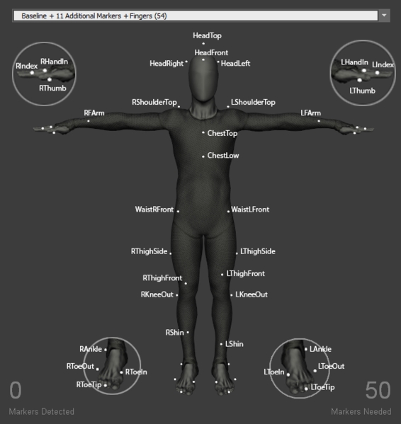
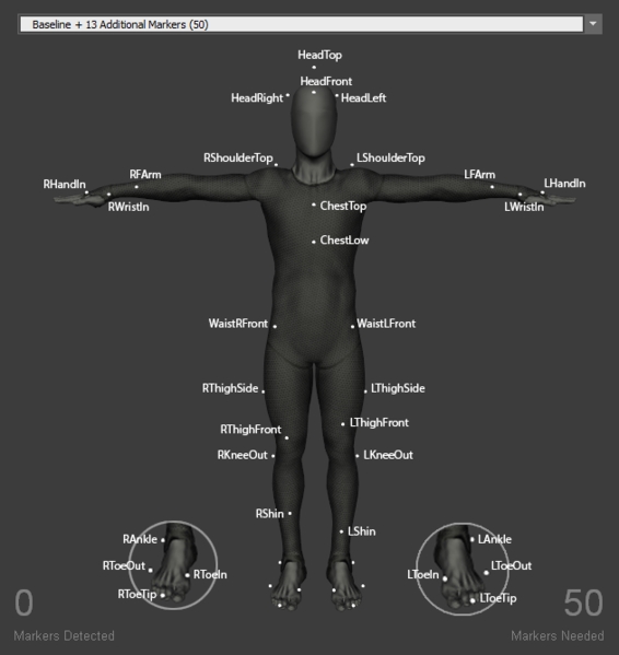
In this marker set, there are multiple additional markers added to the Baseline (37). The marker placement can be found in the Builder pane. The following chart provides additional explanations on the marker locations.
HeadLeft
Head
Included in place of the HeadSide marker. Place the marker on the left side of the head, slight above the ear. For best tracking results, place either the HeadLeft marker or the HeadRight marker slightly further behind the ear in order to introduce more distinct asymmetry to left and right side.
HeadRight
Head
Included in place of the HeadSide marker. Place the marker on the right side of the head, slightly above the ear. See above descriptions for the HeadLeft marker for comments on the asymmetry.
ChestTop
Torso
Included in place of the Chest marker. Place the marker at the center of the chest (sternum); approximately 5 cm below where the neck starts.
ChestLow
Torso
Included in place of the Chest marker. Place the marker where bottom of the two rib cages conjoin; the lowest end of the sternum (xiphoid process).
WaistCBack
Pelvis
Place the marker about 5 cm above the pelvis bone, near the center of the waist back (on the spine) with a slight offset towards the right (or left). This is usually located slightly above one of the dimples located on the waist back (posterior iliac spine bone).
LFArm RFArm
Fore Arm
Place the marker on the front side of the forearm while in T-pose. For best results, slightly offset the left and right forearm markers to introduce the asymmetry on each side.
LHandIn RHandIn
Hand
Place the marker below the knuckle of the index finger.
LThighSide RThighSide
Upper Leg
Place the marker on the lateral side of the thigh. Ideally, L/R ThighSide, L/R KneeOut, and L/R AnkleOut markers should be aligned roughly in a straight line.
Head Markers
LAH RAH
Head
Left Anterior Head Right Anterior Head
Place the markers on the left and right side of the fore head. The respective location is shown in the Skeleton figure.
LPH RPH
Head
Left Posterior head Right Posterior head
Place the markers on the left and right side of the head about 2 cm behind the ear. The respective location is shown in the Skeleton figure.
Torso Markers
Thorax
Sternum Jugular Notch
Top most section of the sternum. Place the marker on the center of the two clavicle bones.
Thorax
Sternum Xiphoid Process
Lowest section of the sternum. Place the marker 1-2 cm above where bottom of the two rib cages conjoin.
Thorax
Cervical Spine Vertebra 7
The 7th cervical spine vertebra is the largest vertebra located at the most inferior region of the neck. This section usually protrudes to the posterior side and can be palpated.
Thorax
Thoracic Spine Vertebra 2
The second thoracic spine vertebra is located three spine levels below the C7 vertebra. Which is located approximately at same height with shoulder joint markers.
Thorax
Thoracic Spine Vertebra 7
Usually located at the center of the thoracic spinal column.
LHGT RHGT
Upper Arm / Shoulder
Left Glenohumeral Joint Right Glenohumeral Joint
Place the marker on the posterior side of the shoulder axis. Ask the subject to posture in T-pose while placing the markers.
Waist Markers
Pelvis
Left Iliac Anterior Spine Right Iliac Anterior Spine
Place the marker on the protruding bones located on the left and right side of the pelvis front.
Pelvis
Left Iliac Posterior Spine Right Iliac Posterior Spine
Place each marker on the two dimples which can be palpated near the spine right above the hips.
Note that the waist markers are the key markers in modeling the pelvis bone, which is the major segment governing the other subsequent Skeleton segments.
Upper Extremity Markers
Thorax
Left Clavicle-Acromion Joint Right Clavicle-Acromion Joint
Ask the subject to stretch both arms towards the side (T-pose), then palpate top of each shoulder for the protruding bone. The prominence is usually located at the end of the corresponding clavicle bone just before where the upper arm starts.
LHLE RHLE
Upper Arm
Left Humerus Lateral Epicondyle Right Humerus Lateral Epicondyle
Placed the markers on the lateral side of the elbow axis. Flex and extend the arm few times to find where elbow axis is located.
LHME* RHME*
Upper Arm
Left Humerus Medial Epicondyle Right Humerus Medial Epicondyle
Place on the medial side of the elbow axis. Ask the subject to flex and extend the arm while placing the markers.
LUA RUA
Upper Arm
Left Upper Arm Right Upper Arm
Ask the subject to stand in T-pose while placing the marker. Palpate to find the groove between the triceps muscles where skin movements are relatively minimal.
Hand Markers
LHM2 RHM2
Hand
Left Hand Second metacarpal Right Hand Second metacarpal
Place the marker slight below the knuckle of the index finger.
LUSP RUSP
Hand
Left Ulna Styloid Process Right Ulna Styloid Process
Place the marker on the lateral side of the wrist axis.
LRSP RRSP
Hand
Left Radius Styloid Process Right Radius Styloid Process
Place the marker on the medial side of the wrist axis.
For best results, place the three hand markers so the created shape is asymmetrical (avoid isosceles shape) and unique from the marker arrangements on the other hand. Since the wrist markers have defined placement — along the wrist axis — introduce small amount of positional offset to the LHM2 and RHM2 markers.
Lower Extremity Markers
Pelvis
Left Femoral greater Trochanter Right Femoral greater Trochanter
Place the markers on left and right side of the hip, where you can palpate the hip joint or the most lateral prominence of the greater trochanter.
Upper Leg
Left Femur Lateral Epicondyle Right Femur Lateral Epicondyle
Place the marker on the lateral prominence of the knee joint axis. More specifically, the marker should be placed on the femur epicondyle. You may need to ask the subject to flex and extend the knee few times to locate the axis.
Upper Leg
Left Femur Medial Epicondyle Right Femur Medial Epicondyle
Place the marker on the Medial prominence of the knee joint axis. Ask the subject to flex and extend the knee few times to locate the knee axis.
LTH RTH
Upper Leg
Left Thigh Right Thigh
Place the markers at the front center of the thigh near the midline. This marker is placed for distinguishing left and right side of the Skeleton. For best results, slightly offset the height of right and left marker to introduce an asymmetry.
LSK RSK
Upper Leg
Left Superior Knee Right Superior Knee
Place the markers on the shin bone near the midline of the lower leg. This marker is placed for distinguishing left and right side of the Skeleton. For best results, slightly offset the height of right and left marker to introduce an asymmetry.
Lower Leg
Left Tibial Tubercle Right Tibial Tubercle
Place the marker about 2-3 cm below the knee cap bone. This marker should be placed on the most anterior point of the tibial tuberosity.
Lower Leg
Left Fibula Apex Right Fibula Apex
While standing, place the markers approximately 5 cm below the LFLE and RFLE markers. This marker should be placed on the lateral prominence of proximal end of the fibula.
The joint center of the knee and the ankle is modeled at the midpoint of the lateral and medial joint markers (FLE/FME and FAL/TAM). Assuming that center of the femoral head aligns with the center of the acetabulum, its virtual location is modeled using markers on the pelvis segment (posterior and anterior iliac spine markers). The lower extremity segments are modeled along these three virtual locations.
Foot Markers
Lower Leg/Foot
Left Fibula Ankle Lateral Right Fibula Ankle Lateral
Place the maker on the lateral side of the ankle axis; on the lateral prominence of the lateral malleolus bone.
Lower Leg/Foot
Left Talus Ankle Medial Right Talus Ankle Medial
Place the maker on the medial side of the ankle axis; on the medial prominence of the medial malleolus bone
Foot
Left Foot Fifth Metatarsal Right Foot Fifth Metatarsal
Place the marker on the dorsal aspect of the fifth metatarsal bone.
Foot
Left Foot Second Metatarsal Right Foot Second Metatarsal
Place the marker on the dorsal aspect of the second metatarsal bone.
Foot
Left Foot First Metatarsal Right Foot First Metatarsal
Place the marker on the dorsal aspect of the first metatarsal bone.
Foot
Left Foot Calcaneus Right Foot Calcaneus
Place the marker on center of the heel, where the Achilles tendon attaches to the calcneous bone.
LDP1 RDP1
Toes
Left First Distal Phalanx Right First Distal Phalanx
Place the marker near the end of the big toe. More specifically, the marker should be placed at the distal end of the first phalanges.
Leardini, A., Biagi, F., Merlo, A., Belvedere, C., Benedetti, M.G., 2011. Multi-segment trunk kinematics during locomotion and elementary exercises. Clin. Biomech. 26, 562-571.
Leardini, A., Sawacha, Z., Paolini, G., Ingrosso, S., Nativo, R., Benedetti, M.G., 2007. A new anatomically based protocol for gait analysis in children. Gait Posture 26. 560-571.
This Marker Set can be used with Active Tags in conjunction with the Core Marker Set.
The Baseline + Active Fingers Marker Set has the same placement for the body as the Baseline Marker Set, however, there are additional Active markers on the wrist, hand, and fingers.
The Active Finger Markerset uses a total of 10 markers per hand, 8 active with 2 passive markers attached at the wrist.
LWristOut RWristOut
Fore Arm / Hand
Place the marker on the outside (lateral side) of the wrist axis. (distal end of the radius bone). Note that the wrist axis is not always located on the protruding bone but 1-2 cm more towards the hand.
LWristIn RWristIn
Fore Arm / Hand
Place the marker on the inner prominence (medial side) of the wrist axis (distal end of the ulnar bone).
LHandOut RHandOut
Hand
Place the marker slightly below the pinky knuckle. More specifically, between distal end of the fifth and fourth metacarpal bones.
LHandIn RHandIn
Hand
Place the marker slightly below the forefinger knuckle. More specifically, between distal end of the second metacarpal bones.
LThumb RThumb
Finger
Place the marker on the thumb on the 1st metacarpophalangeal joint
LFingers RFingers
Finger
Place markers on the tips of each finger and thumb
The active finger Marker Set utilizes the tracking capability of active markers and the active labeling features to accomplish tracking of both the hands and the fingers. These Marker Sets require the tracking solution and a set of Tag(s). Wired from an active Tag, each active marker must attach to the expected locations. For each hand, 8 active markers are needed, with 2 passive markers attached at the wrist.
Manus VR Gloves
Alternatively, you can also use Manus VR Gloves for tracking the fingers. For more information, refer to the page.
The Active BaseStation
Active Tag(s) with active markers.
A way to attach active markers onto the hands (e.g., gloves).
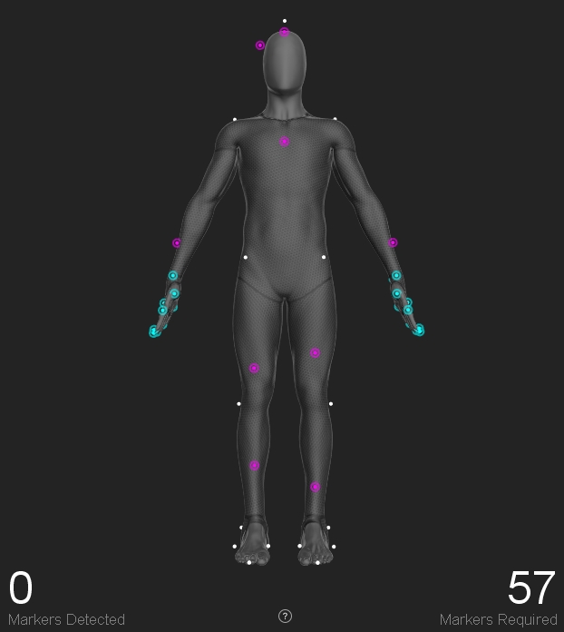
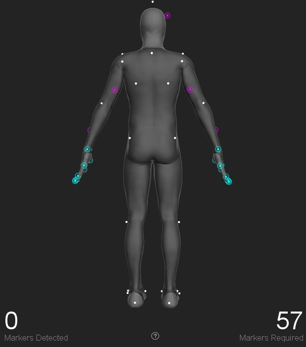
Baseline + Active Fingers (57)
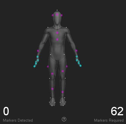
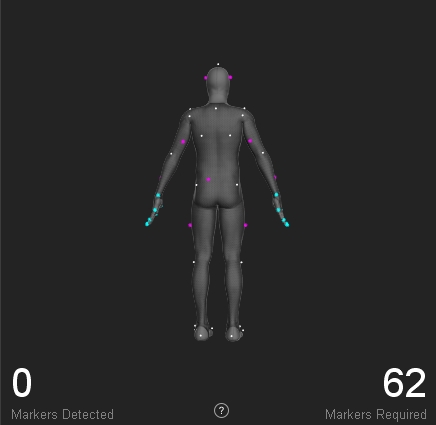
Core + Active Fingers (62)
Right Hand + Active Fingers (10)
Left Hand + Active Fingers (10)
Please note that the numbers listed in the Marker Set names are the total number of markers needed, including both active and passive markers.
Total of 10 markers will be attached on each hand (8 Active markers and 2 passive).
Tags: Attach Tags to each hand for the active LEDs.
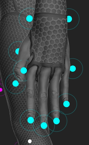
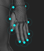
Passive Markers (2): Attach the 2 passive markers to both sides of the wrist, directly on the joints of either side along the wrist flexion point.
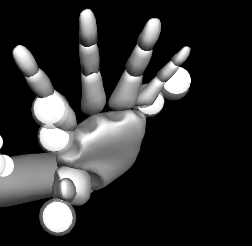
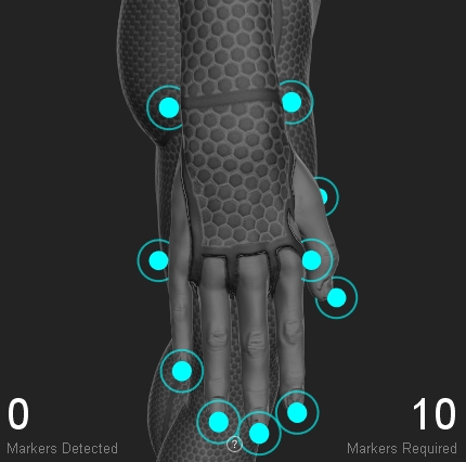
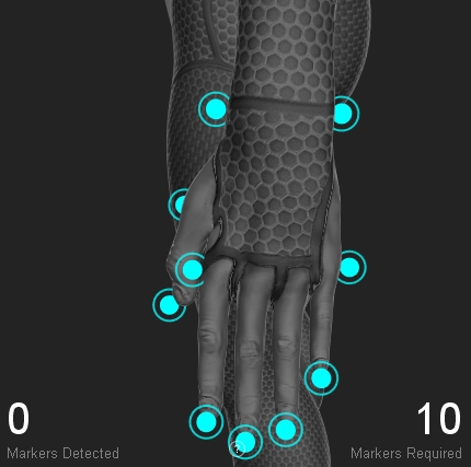
Active Markers (8): Each Tag connects up to 8 active markers. Position the wired active markers at the tip of all five fingers (5), one each on the knuckle of the index finger and the pinky finger (2), and place the remaining active marker on the inside of the bottom thumb joint.
Steps for creating an active finger Marker Set is the same as the other skeleton Marker Set:
Make sure all of the markers are placed in the correct positions. For the Core + Active Fingers (62) Marker Set, please make sure the passive full body tracking markers are also placed on the person's body.
Select the finger markers in the 3D viewport.
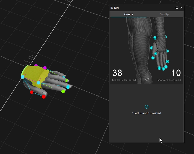
Click Create.
Note that the waist markers are the key markers in modeling the pelvis bone, which is the major segment governing the other subsequent Skeleton segments.
The joint center of the knee and the ankle is modeled at the midpoint of the lateral and medial joint markers (FLE/FME and FAL/TAM). Assuming that center of the femoral head aligns with the center of the acetabulum, its virtual location is modeled using markers on the pelvis segment (posterior and anterior iliac spine markers). The lower extremity segments are modeled along these three virtual locations.
Leardini, A., Biagi, F., Merlo, A., Belvedere, C., Benedetti, M.G., 2011. Multi-segment trunk kinematics during locomotion and elementary exercises. Clin. Biomech. 26, 562-571.
Leardini, A., Sawacha, Z., Paolini, G., Ingrosso, S., Nativo, R., Benedetti, M.G., 2007. A new anatomically based protocol for gait analysis in children. Gait Posture 26. 560-571.
Note that the waist markers are the key markers in modeling the pelvis bone, which is the major segment governing the other subsequent Skeleton segments. For best results, avoid placing the waist markers in a rectangle shape. When tracking multiple actors with similar proportions, introduce an offset to one of the WaistBack marker, or the WaistCMarker (included only with the 13 additional Marker Set), to create an asymmetrical arrangements.
Hinged toe Marker Sets create toe segments in the Skeleton. Two additional markers are added to each foot, one on the toe-tip and another on the heel. The hinged toe markers are included in all baseline Marker Sets except for Baseline (37) and Upper Body Marker Sets.
SJN (IJ)
SXS (PX)
CV7 (C7)
TV2 (T2)
TV7 (T7)
LIAS (PSISl) RIAS (PSIS)
LIPS (ASIS) RIPS (ASIS)
LCAJ (LA) RCAJ (RA)
LFLE (LE) RFLE (LE)
LTTC (TT) RTTC (TT)
LFAL(LM) RFAL
LFM2* (SM) RFM2*
LFCC (CA) RFCC
SJN (IJ)
SXS (PX)
CV7 (C7)
TV2 (T2)
TV7 (T7)
LIAS (PSISl) RIAS (PSIS)
LIPS (ASIS) RIPS (ASIS)
LCAJ (LA) RCAJ (RA)
SJN (IJ)
SXS (PX)
CV7 (C7)
TV2 (T2)
TV7 (T7)
LIAS (PSISl) RIAS (PSIS)
LIPS (ASIS) RIPS (ASIS)
LCAJ (LA) RCAJ (RA)
LFTC (GT) RFTC (GT)
LFLE (LE) RFLE (LE)
LFME* (ME) RFME* (ME)
LTTC (TT) RTTC (TT)
LFAX (HF) RFAX (HF)
LFAL(LM) RFAL
LTAM* (MM) RTAM*(MM)
LFM5(VM) RFM5
LFM2* (SM) RFM2*
LFM1 (FM) RFM1
LFCC (CA) RFCC
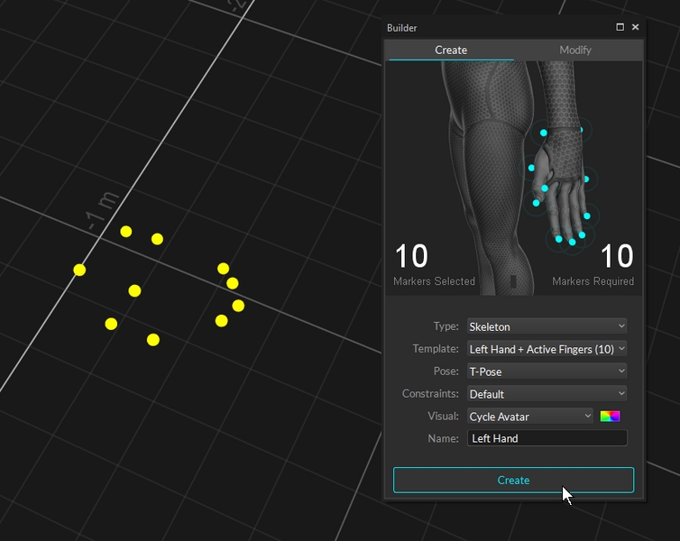
Open the and select the desired hand Marker Set under the drop-down menu.
Once the markers have been placed, ask the subject to strike the .
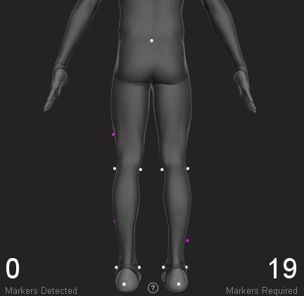
The Marker Detected must match Marker Required in the .
Upper Leg
Left Femur Lateral Epicondyle Right Femur Lateral Epicondyle
Place the marker on the lateral prominence of the knee joint axis. More specifically, the marker should be placed on the femur epicondyle. You may need to ask the subject to flex and extend the knee few times to locate the axis.
Upper Leg
Left Femur Medial Epicondyle Right Femur Medial Epicondyle
Place the marker on the Medial prominence of the knee joint axis. Ask the subject to flex and extend the knee few times to locate the knee axis.
Upper Leg
Left Thigh Right Thigh
Place the markers at the front center of the thigh near the midline. This marker is placed for distinguishing left and right side of the Skeleton. For best results, slightly offset the height of right and left marker to introduce an asymmetry.
Upper Leg
Left Superior Knee Right Superior Knee
Place the markers on the shin bone near the midline of the lower leg. This marker is placed for distinguishing left and right side of the Skeleton. For best results, slightly offset the height of right and left marker to introduce an asymmetry.
Lower Leg/Foot
Left Fibula Ankle Lateral Right Fibula Ankle Lateral
Place the maker on the lateral side of the ankle axis; on the lateral prominence of the lateral malleolus bone.
Lower Leg/Foot
Left Talus Ankle Medial Right Talus Ankle Medial
Place the maker on the medial side of the ankle axis; on the medial prominence of the medial malleolus bone
Foot
Left Foot Calcaneus Right Foot Calcaneus
Place the marker on center of the heel, where the Achilles tendon attaches to the calcaneus bone.
Toe
Left Foot 2nd Distal Phalanx Right Foot 2nd Distal Phalanx
Place the marker on the 2nd Distal Phalanx between the
Pelvis
Left Iliac Anterior Spine Right Iliac Anterior Spine
Place the marker on the protruding bones located on the left and right side of the pelvis front.
Pelvis
Left Iliac Posterior Spine Right Iliac Posterior Spine
Place each marker on the two dimples which can be palpated near the spine right above the hips.
Upper Leg
Left Femur Lateral Epicondyle Right Femur Lateral Epicondyle
Place the marker on the lateral prominence of the knee joint axis. More specifically, the marker should be placed on the femur epicondyle. You may need to ask the subject to flex and extend the knee few times to locate the axis.
LTH RTH
Upper Leg
Left Thigh Right Thigh
Place the markers at the front center of the thigh near the midline. This marker is placed for distinguishing left and right side of the Skeleton. For best results, slightly offset the height of right and left marker to introduce an asymmetry.
LSK RSK
Upper Leg
Left Superior Knee Right Superior Knee
Place the markers on the shin bone near the midline of the lower leg. This marker is placed for distinguishing left and right side of the Skeleton. For best results, slightly offset the height of right and left marker to introduce an asymmetry.
Lower Leg
Left Tibial Tubercle Right Tibial Tubercle
Place the marker about 2-3 cm below the knee cap bone. This marker should be placed on the most anterior point of the tibial tuberosity.
LFAL(LM[2]) RFAL
Lower Leg/Foot
Left Fibula Ankle Lateral Right Fibula Ankle Lateral
Place the maker on the lateral side of the ankle axis; on the lateral prominence of the lateral malleolus bone.
LFM2* (SM[2]) RFM2*
Foot
Left Foot Second Metatarsal Right Foot Second Metatarsal
Place the marker on the dorsal aspect of the second metatarsal bone.
LFCC (CA[2]) RFCC
Foot
Left Foot Calcaneus Right Foot Calcaneus
Place the marker on center of the heel, where the Achilles tendon attaches to the calcneous bone.
WaistLFront WaistRFront
Pelvis
Placed the marker on the protruding bone located on the front of the pelvis (left/right anterior iliac spine bone). The prominence can be palpated from left and right side of the waist.
WaistLBack WaistRBack
Pelvis
Place the WaistLBack and WaistRBack markers above left/right hip; about 10 cm above the hip joint.
LThighFront RThighFront
Upper Leg
Place the marker on the front side of the thigh, along the midline. For best results, slightly offset the height of the left and right markers to introduce the asymmetry.
LKneeOut RKneeOut
Upper Leg
Place the marker on the outer prominence of the knee joint; on the lateral epicondyle of the femur. Palpate the knee for the protruding bone from the upper leg, and place it right on the axis. Ask the actor to flex and extend the knee few times to confirm that the markers are placed along the axis and maintain stationary throughout the range of motion cycles.
LShin RShin
Lower Leg
Place the marker on the shin bone; on the midline of the lower leg. For best results, slightly offset the height of the left and right markers to introduce the asymmetry.
LAnkleOut RAnkleOut
Lower Leg/Foot
Place the marker on the protruding bone outside of the ankle joint; on the lateral end of the malleolus bone.
LToeOut RToeOut
Foot
Place the marker just before the little toe joint; on the distal end of the fifth metatarsal bone.
LToeIn RToeIn
Foot
Place the marker just before the big toe joint; on the distal end of the first metatarsal bone.
LHeel RHeel
Foot
Place at the center of the heel.
LToeTip RToeTip
Toe
Place the marker on the tip of the second toe; next to the big toe.
This page provides instructions on integrating StretchSense gloves with an OptiTrack motion capture system.
Starting from Motive 3.0 and above, StretchSense gloves can be integrated into Motive. This allows for easy integration of the external glove tracking system directly in Motive so that it can be used in tandem with the OptiTrack system to provide a more comprehensive tracking solution.
Required Components
StretchSense SuperSlay or Fidelity Gloves with corresponding dongles.
Hand Engine 2.2.2+ software
Motive 3.0 or above
(optional) MoCap suit and markers for full body capture.
(optional) 2 PCs, one to run Motive another to run Hand Engine
If you're having issues with latency, it is recommended that you run Hand Engine on a separate PC than Motive. For more instruction on how to do so, please see our Connecting to Remote Host section Below.
Before getting setup in Motive, you'll need to pair and calibrate your gloves within Hand Engine . Hand Engine is StretchSense's software that allows you to pair your gloves to their respective USB dongles and calibrate prior to integrating into Motive.
For a full guide on setting up your gloves with Hand Engine, please visit the StretchSense Knowledge Base.
In order for StretchSense gloves to appear in the Devices pane in Motive, you'll first need to download the StretchSense DLL from our website.
Once downloaded, you can place the DLL file into the directory below:
C:\Program Files\OptiTrack\Motive\devices
You will want to make sure Motive is not open during this process. Once the DLL has been stored in the devices folder, you can then open Motive.
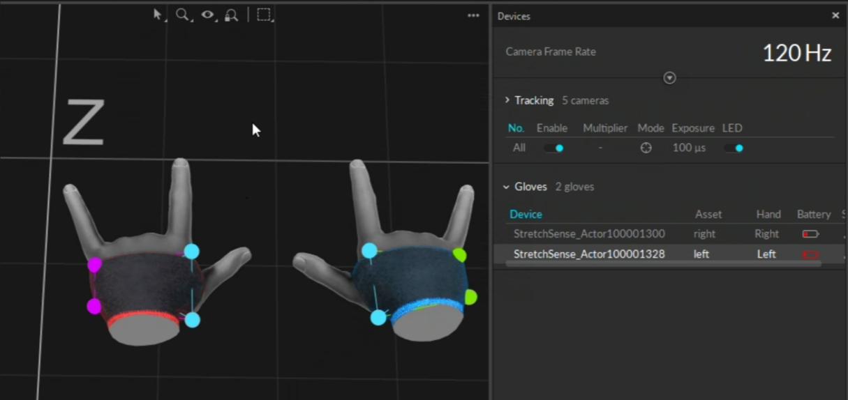
Open Motive and power on the StretchSense gloves. You'll see the gloves appear in the Devices pane.
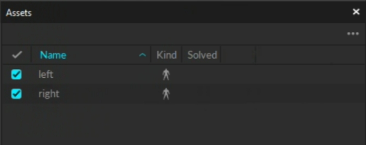
Create 2 hand Skeletons from the glove markers (left, and right hands).
From the Devices pane select the Right glove and pair it to the right Skeleton.
Repeat Step 5 with the left hand.
Your gloves should now be fully integrated into Motive and ready for tracking!
To improve any latency issues, you can follow the steps below for running Motive and Hand Engine on separate PCs.
On the host computer, make sure Hand Engine is running with 'Enable SDK' option turned on.
On the separate Motive PC, open Motive.
In Motive Settings -> General -> Glove Server Address, specify the IP address and port number of the remote Hand Engine instance. Glove Server Address is an advanced property, so 'Show Advanced' must be toggled. The IP address must follow with a colon ":" and then a port number that matches the number defined in Hand Engine. (e.g. 192.168.1.5:50051)
Check the Log pane in Motive to confirm the connection. If the plugin stopped detecting, restart Motive.
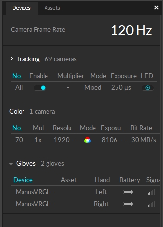
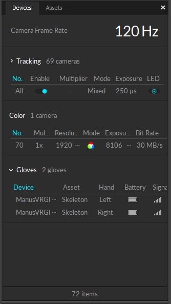
Below is a description of the columns associated with the gloves in the Devices pane.
This is the name of the device. By default the naming convention is 'StretchSense_Actor #Serial number'. This is useful to identify each glove based on its serial number incase it was incorrectly paired in Hand Engine .
This column will populate with the Skeleton Asset that the glove was paired to within Motive.
This column denotes the left and right hands as they were setup in Hand Engine. If the gloves were incorrectly paired in Hand Engine, they will be incorrectly displayed here as well.
This column displays the current battery level of the gloves.
This column denotes the signal strength. It is important to make sure the signal strength is as full as possible for the best tracking experience.
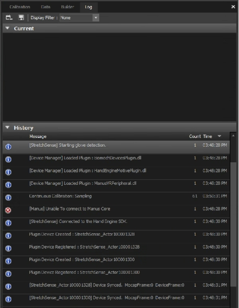
Important information regarding the status of the gloves as they integrate into Motive can be found in the Log pane.
This denotes that Motive is now connected to Hand Engine.
Prepares the glove to be created in Motive.
Creates the glove instance in Motive and populates the glove in the Devices pane.
This message should only appear initially and may occur if there are camera frame drops in other parts of your system. For the most part however, this isn't necessary general user information.
Basic setup and troubleshooting guide for integrating Manus Glove devices with Motive.
The Manus Glove device integration brings finger tracking data from the external glove tracking system into Motive, providing a more comprehensive tracking solution.
Visit the Manus website to download and install the necessary software.
For detailed instructions on using Manus gloves, including the OptiTrack integration, please see the OptiTrack Motive plugin documentation on the Manus Knowledge Center.
Required Components
Manus Gloves and the USB Dongle.
Manus Core and Dashboard software.
Motive 3.0 or above.
(optional) MoCap suit and markers for full body capture.
Important Notes
Supported Glove Models: Manus Prime gloves and Quantum Metagloves.
Sampling Rate: Manus gloves run at a fixed sampling rate of 90Hz. If the camera system is set to run at a higher frame rate higher, Motive will pad the missing samples in the glove data with previous samples.
Sync: Manus gloves do not support hardware synchronization. Motive uses a software synchronization scheme to attempt to keep the Manus glove as close as possible to mocap data.
Manus Dongle: Plug the Manus dongle on a separate USB bus from the one used to connect the USB Security Key. If both dongles are connected to the same bus, it may cause conflicts with Motive activation.
The steps required to setup the glove may change depending on Manus Software versions. For the latest information, please refer to the Manus user documentation.
Before using Manus gloves in Motive, please ensure all gloves have been paired, calibrated and are able to report data from the Manus Dashboard software. This is a crucial first step for the successful use of Manus Gloves with Motive software.
Start the Manus Dashboard software.
Insert the Manus Glove Dongle(s) onto the computer. Do not connect the dongle into the same USB bus used by the USB Security Key as it can cause conflicts with device detection.
Power on the Manus Gloves.
(optional) You may need to pair the glove with the dongle. The gloves should come already paired.
Calibrate each glove according to the Manus user documentation. This step is critical to provide the most robust finger solve data.
Start Motive and the gloves should appear in the Devices pane.
Note: We recommend closing the Manus Dashboard while running Motive to prevent performance issues.
Please refer to our Glove Device Setup page.
The easiest method to properly align the constraints with the device is to place a camera in MJPEG mode (reference mode) and use the Gizmo tool to make adjustments.
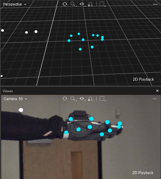
Adjust the gain and exposure on the reference camera until the actor's hand in the Manus glove is clearly visible.
Once Motive is tracking the glove, the finger tracking data can be output for various applications. Real-time finger data can be streamed into any NatNet client, and recorded finger data can be exported into other file formats. For instructions, please refer to the following pages:
Manus Core requires the appropriate license for streaming to Motive. If that license is not found, Motive will report an error when the program is launched.
Until the proper license is installed, the gloves will appear in Motive, but when paired with a hand skeleton there is no hand animation as expected.
Contact Manus support to resolve Manus licensing issues.
The Log pane will record several informational entries when Manus gloves are connected:
The following Log pane entries indicate that additional steps are required to connect the gloves:
Failed to Load Plugin | Unable to Load dll ... The specified module could not be found | ManusCore not found on %s", szServerAddress | ManusCore not found on localhost | Failed to initialize the ManusSDK | Error: %s", p_SystemMessage->infoString | Incompatible SDK version. Use 2.0 or above | Skeleton-Related Error Messages
The OptiTrack Manus plugin did not load when Motive was initialized.
Troubleshooting Steps:
make the correct version of Plugin.dll is in the devices folder.
make sure ManusSDK.dll is in the same folder as Motive.exe.
The plugin DLL was found but not loaded due to missing dependencies. This indicates the plugin setup is incomplete.
Troubleshooting Steps:
Reinstall the plugin.
Contact Manus support.
The ManusCore application was not found at the designated server address.
Troubleshooting Steps:
Ensure the correct server address is indicated for the ManusCore PC.
Check that the ManusCore PC is running and that the software is installed.
The ManusCore application was not found on the Motive PC.
Troubleshooting Steps:
Ensure that the Motive PC has the ManusCore application installed.
The ManusSDK did not initialize.
Troubleshooting Steps:
Restart the ManusCore and Motive PCs.
See Manus support for additional troubleshooting.
Error callback from Manus SDK.
Troubleshooting Steps:
Contact Manus support for the specific message received.
Error reported from ManusSDK
Troubleshooting Steps:
Contact Manus support.
The following error messages indicate issues with the skeleton in Manus.
[Manus] Failed to load the skeleton
Failed initialization of Manus skeleton
[Manus] Failed to give skeleton an ID
Failed initialization of Manus skeleton
[Manus] Failed to create skeleton setup
Skeleton chaining error
[Manus] Failed to create skeleton chains.
Skeleton chaining error
[Manus] Error with setting up right hand skeleton node.
Failed initialization of Hand skeleton
[Manus] Error with setting up left hand skeleton node.
Failed initialization of Hand skeleton
[Manus] Failed to Add Chain To Skeleton Setup. Error Code: %d", result
Skeleton chaining error. Error code from ManusSDK
Troubleshooting Steps:
Check the configuration in Manus Dashboard and make sure the hand skeleton is correctly defined and working there.
Contact Manus support.
LWristOut RWristOut
Fore Arm / Hand
Place the marker on the outside (lateral side) of the wrist axis. (distal end of the radius bone). Note that the wrist axis is not always located on the protruding bone but 1-2 cm more towards the hand.
LWristIn RWristIn
Fore Arm / Hand
Place the marker on the inner prominence (medial side) of the wrist axis (distal end of the ulnar bone).
LHandOut RHandOut
Hand
Place the marker slightly below the pinky knuckle. More specifically, between distal end of the fifth and fourth metacarpal bones.
LHandIn RHandIn
Hand
Place the marker slightly below the forefinger knuckle. More specifically, between distal end of the second metacarpal bones.
Pelvis
Left Iliac Anterior Spine Right Iliac Anterior Spine
Place the marker on the protruding bones located on the left and right side of the pelvis front.
Sacrum
Lower spine
Place this marker in the lower spine over the S2 vertebrae.
LWristOut RWristOut
Fore Arm / Hand
Place the marker on the outside (lateral side) of the wrist axis. (distal end of the radius bone). Note that the wrist axis is not always located on the protruding bone but 1-2 cm more towards the hand.
LWristIn RWristIn
Fore Arm / Hand
Place the marker on the inner prominence (medial side) of the wrist axis (distal end of the ulnar bone).
LHandOut RHandOut
Hand
Place the marker slightly below the pinky knuckle. More specifically, between distal end of the fifth and fourth metacarpal bones.
LHandIn RHandIn
Hand
Place the marker slightly below the forefinger knuckle. More specifically, between distal end of the second metacarpal bones.
LThumb RThumb
Finger
Place the marker on the thumb on the outside of 1st metacarpophalangeal joint.
LFingers RFingers
Finger
Place markers on the tips of each finger and thumb
Before starting Motive, please make sure to launch your glove's software first.
Launch Motive. Connected gloves will be listed under the Devices pane.
Use the Builder pane to define a Skeleton asset in Motive. You can use any Skeleton model that is not designed to track fingers using motion capture data. The recommended Skeletons models to use are the Core 50 or Baseline 41.
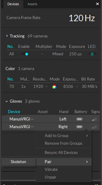
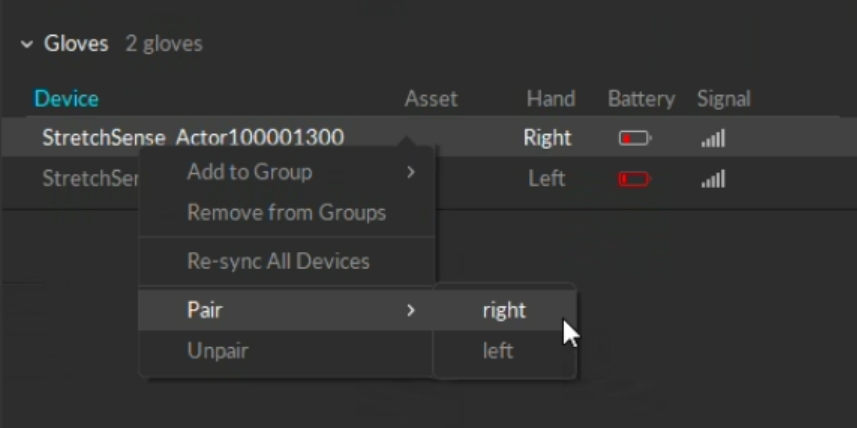
After a Skeleton has been defined, pair the Skeleton to the glove device. Open the Devices pane, right-click on the listed glove device, and pair it to the Skeleton as shown in the screenshot below.
Once the glove has been configured and paired with the created Skeleton, the fingers will be tracking in Motive.
Once Motive starts tracking the glove, the finger tracking data can be outputted for various applications. Real-time finger data can be streamed into any NatNet client, and recorded finger data can be exported into other file formats. For instructions on outputting tracking data from Motive, refer to the following pages:
Rizzoli Marker Sets protocols are available in Motive for human motion tracking. The Rizzoli protocols are developed and researched from the Movement Analysis Laboratory in the Rizzoli Orthopedics Institute, Italy.
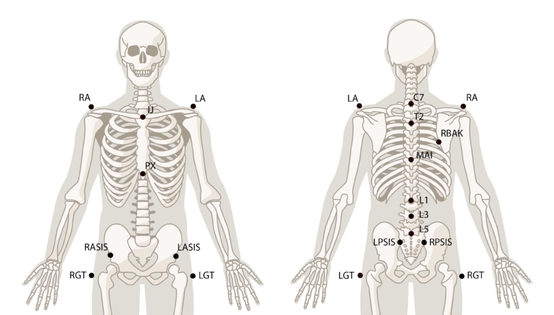
In biomechanics tracking applications, proper marker placements are critical to the human motion tracking and the respective biomechanical analysis; and for this reason, precise identification of the anatomical landmarks and marker placements have to be performed[1]. With a Motive Body license, marker locations are indicated over the avatar displayed in the Builder pane. This page provides additional details on the anatomical locations of the marker placements for the Rizzoli protocols.
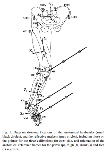
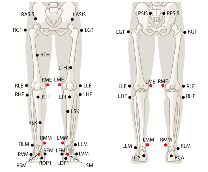
The Rizzoli Lower Body template integrates a novel marker placement for lower body tracking. This Marker Sets is designed to provide a complete description of 3D segment and joint motion for analyzing the pelvis and lower extremity kinematics[1]. The following chart includes anatomical landmark descriptions of where the markers need to be placed for accurate and reliable analysis of the lower body movement.
Includes total six calibration markers for creating the Skeleton asset during static trials (RME/LME, RMM/LMM, RSM/LSM). They are highlighted in red.
Two thigh markers (RTH and LTH) and two shank markers (RSK and LSK) have been added to the protocol to better distinguish the left and right of the Skeleton.
For more information on the segment and joint definitions, please refer to the referenced research papers.
Rizzoli Lower Body Protocol Markers
Pelvis
Anterior superior iliac spine.
Pelvis
Posterior superior iliac spine.
Upper Leg
Most lateral prominence of the greater trochanter external surface.
RTH LTH
Upper Leg
Place near the midline of the thigh. Used only for a tracking purpose of distinguishing left and right side. For best result, offset the height of the marker between left and right side.
Upper Leg
Most lateral prominence of the lateral femoral epicondyle. Together with LM markers, it determines the location of knee joint axis.
Lower Leg
Head, proximal end, of the fibula.
Lower Leg
Most anterior border of the tibial tuberosity.
RSK LSK
Upper Leg
Place near the midline of the shin. Used only for a tracking purpose of distinguishing left and right side. For best result, offset the height of the marker between left and right side.
Lower Leg
Distal apex of the lateral malleolus.
Foot
Foot
Dorsal aspect of fifth metatarsal head.
Foot
Dorsal aspect of first metatarsal head.
RDP1 LDP1
Foot
These markers are added on the distal phalanx only for the toe segment tracking purpose, and they are not included in the biomechanical analysis. Place the marker near the end of the big toe. More specifically, the marker should be placed at the distal end of the first phalanges.
Upper Leg
Medial prominence of the medial femoral epicondyle.
Lower Leg
Distal apex of the medial malleolus.
Foot
Dorsal aspect of second metatarsal head.
*These markers need to be removed after the Skeleton has been created in Motive.
This Marker Set is designed for tracking multi-segment trunk kinematics[2]. Total 10 markers are place on the torso and 4 markers are placed around pelvis[2], and an extra back marker (RBAK) was added on the right scapula solely for improved tracking.
Total four markers are used for tracking the thorax segment, where two acromion markers (RA and LA) make the shoulder line segment for tracking the segment rotation and translations[2].
For the spine motion tracking, a 5-link segment model is created from the six spine markers[2].
An extra RBAK marker was added to the protocol for improved identification of left and right side of the tracked Skeleton.
For more information on the Rizzoli Trunk Marker Set, please refer to the referenced research papers.
Rizzoli Trunk Markers
Torso
Acromio-clavicular joint
RBAK
Torso
Placed near the right scapula apex: Used only to Identify left and right of the Skeleton.
Torso
Seventh cervical vertebrae.
Torso
Second thoracic vertebrae
Torso
Midpoint between left and right scapular apex, near the T10 vertebrae.
Torso
Jugular Notch. Most superior region of the sternum, where it meets the clavicle bones.
Torso
Xiphoid process of the sternum. Most inferior region of the sternum.
Torso
First lumbar vertebrae.
Torso
Third lumbar vertebrae.
Torso
First lumbar vertebrae.
Pelvis
Anterior superior iliac spine.
Pelvis
Posterior superior iliac spine.
The Rizzoli Body template combines the Rizzoli Lower Body Protocol and the Rizzoli Trunk Protocol to provide tracking of the full-body kinematics.
Rizzoli Full Body Markers
Torso
Acromio-clavicular joint
RBAK
Torso
Placed near the right scapula apex: Used only for identifying left and right of the Skeleton.
Torso
Seventh cervical vertebrae.
Torso
Second thoracic vertebrae
Torso
Midpoint between left and right scapular apex, near the T10 vertebrae.
Torso
Jugular Notch. Most superior region of the sternum, where it meets the clavicle bones.
Torso
Xiphoid process of the sternum. Most inferior region of the sternum.
Torso
First lumbar vertebrae.
Torso
Third lumbar vertebrae.
Torso
First lumbar vertebrae.
Pelvis
Anterior superior iliac spine.
Pelvis
Posterior superior iliac spine.
Upper Leg
Most lateral prominence of the greater trochanter external surface.
RTH LTH
Upper Leg
Place near the midline of the thigh. Used only for a tracking purpose of distinguishing left and right side. For best result, offset the height of the marker between left and right side.
Upper Leg
Most lateral prominence of the lateral femoral epicondyle. Together with LM markers, it determines the location of knee joint axis.
Lower Leg
Head, proximal end, of the fibula.
Lower Leg
Most anterior border of the tibial tuberosity.
RSK LSK
Upper Leg
Place near the midline of the shin. Used only for a tracking purpose of distinguishing left and right side For best result, offset the height of the marker between left and right side.
Lower Leg
Distal apex of the lateral malleolus.
Foot
Foot
Dorsal aspect of fifth metatarsal head.
Foot
Dorsal aspect of first metatarsal head.
Foot
These markers are added on the distal phalanx only for the toe segment tracking purpose, and they are not included in the biomechanical analysis. Place the marker near the end of the big toe. More specifically, the marker should be placed at the distal end of the first phalanges.
Upper Leg
Medial prominence of the medial femoral epicondyle.
Lower Leg
Distal apex of the medial malleolus.
Foot
Dorsal aspect of second metatarsal head.
*These markers need to be removed after the Skeleton has been created in Motive.
The Rizzoli Left/Right Foot template provides precise tracking of the foot kinematics by modeling three-foot segments – rear-foot, mid-foot, and fore-foot – from the markers that are placed on carefully identified anatomical landmarks of the foot [3]. The following diagrams and the chart detail on where each marker needs to be placed on the right foot protocol. The placements for the left foot will be anatomically equivalent but reflected.
There are two calibration markers in each foot protocol. They are located at the apex of the medial malleolus (RMM/LMM) and the lowest point of the heel center (RCAp/LCAp). These markers are only for creating the asset for static trials, and they need to be removed for dynamic trials.
Refer to the referenced papers for specific information on the joint and segment definitions.
Rizzoli Foot Markers
Distal apex of the medial malleolus.
*These markers need to be removed after the Skeleton has been created in Motive.
Leardini, A., Sawacha, Z., Paolini, G., Ingrosso, S., Nativo, R., Benedetti, M.G., 2007. A new anatomically based protocol for gait analysis in children. Gait Posture 26. 560-571.
Leardini, A., Biagi, F., Merlo, A., Belvedere, C., Benedetti, M.G., 2011. Multi-segment trunk kinematics during locomotion and elementary exercises. Clin. Biomech. 26, 562-571.
Leardini, A., Benedetti, M.G., Berti, L., Bettinelli, D., Nativo, R., Giannini, S., 2007. Rear-foot, mid-foot and fore-foot motion during the stance phase of gait. Gait Posture 25. 453-462.
Portinaro, N., Leardini, A., Panou, A., Monzani, V., Caravaggi, P., 2014. Modifying the Rizzoli foot model to improve the diagnosis of pes-planus: application to kinematics of feet in teenagers. Journal of Foot and Ankle Research 7, 57.
There are two different Skeleton marker templates that can be used for entertainment applications: Baseline and Core. Both of these Marker Sets provide high-quality tracking, but the Core marker set templates may provide more stable tracking for high-camera count systems.
Among these marker sets, some of the placements are shared. For example, the Baseline (41) Marker Sets serves as a starting point, and the other baseline Marker Sets add more markers to it. When attaching the markers, you should reference the Skeleton avatar from the for relative locations. The following charts and pages provide additional descriptions to where each marker should be placed, find related markers or click on one of the baseline Marker Sets pages for specific placement descriptions.
Asymmetry
Asymmetry is the key to avoiding the congruency for tracking multiple Marker Sets. When there are more than one similar marker arrangements in the volume, marker labels may be confused. Thus, it is beneficial to place segment makers — joint markers must always be placed on anatomical landmarks — in asymmetrical positions for similar rigid bodies and skeletal segments. This provides a clear distinction between two similar arrangements. Furthermore, avoid placing markers in a symmetrical shape within the segment as well. For example, a perfect square marker arrangement will have ambiguous orientation and frequent mislabels may occur throughout the capture. Instead, follow the rule of thumb of placing the less critical markers in asymmetrical arrangements.
List of Baseline marker set templates
List of Core marker set templates
Note that the waist markers are the key markers in modeling the pelvis bone, which is the major segment governing the other subsequent Skeleton segments. For best results, avoid placing the waist markers in a rectangle shape. When tracking multiple actors with similar proportions, introduce an offset to one of the WaistBack marker, or the WaistCMarker (included only with the 13 additional Marker Set), to create an asymmetrical arrangements.
For best results, place the hand markers so that the shape of the marker arrangement is asymmetrical itself and also unique to the shape on the other hand. Since the wrist marker placement is fixed along the wrist axis, offset the HandOut or the HandIn markers to create the unique arrangements. For more robust and simple tracking, hand rigid-bodies can be attached on the hand to replace the markers and guarantee the asymmetrical and non-deforming marker placement.
This page provides step-by-step instructions for creating the rigid body based skeleton Marker Sets in Motive.
Please note that Motive: Body license is required to access and use the rigid body skeleton Marker Sets. This is not supported with Motive: Tracker license.
6 Rigid Body Skeleton in Motive.
The Rigid Body Skeleton Marker Sets allows users to use rigid bodies to establish skeleton tracking. Rigid bodies are attached to head, torso, both hands, and both feet (6 rigid body skeleton only). Then, using the tracking information, Motive solves the entire skeleton through inverse kinematics. There are three types of rigid body skeleton Marker Sets in Motive:
6 Rigid Body Skeleton
4 Rigid Body Skeleton
4 Rigid Body Skeleton + Active Fingers
Step 1. Prepare the rigid bodies
For 6 rigid body skeleton, a total 6 rigid bodies are needed: head (1), torso (1), both hands (2), and both feet (2)
For 4 rigid body skeleton, a total 4 rigid bodies are needed: head (1), torso (1), both hands (2)
Step 2. Attach the rigid bodies to the actor
Step 1: Create a rigid body asset for the rigid body attached to Chest/Hip
Only one of the Chest or the Hip rigid body is needed for the 6 rigid body skeleton.
Step 2: Position the pivot point of the Chest/Hip rigid body
For the chest rigid body, the pivot point must be placed at the center of the torso, approximately at the heart center, which is in between the spine and the bottom end of the sternum. For the hip rigid body, the pivot point must be placed at the center of the hip bone.
Step 3: Orient the pivot point of the Chest/Hip rigid body
Enabling the Bone Orientation setting under the rigid body properties will reveal the orientation of the selected rigid body.
Step 4: Create the HMDhead/Head rigid body
Now that the chest, or hip, rigid body has been set up, next step is to create a rigid body for the head. This can be either the active HMD clip or a rigid body attached to the head. Only one of these needs to be created.
Under the Type drop-down menu, select HMD. This will bring up the options for defining an HMD rigid body.
Under the Orientation drop-down menu, select the desired orientation of the HMD.
Hold the HMD at the center of the tracking volume where all of the active markers are tracked well.
Name the rigid body as HMDHead for +Z-forward orientation or HMDHeadX for +X-forward orientation.
Click Create. An HMD rigid body will be created from the selected markers and it will initiate the calibration process.
During calibration, slowly rotate the HMD to collect data samples in different orientations.
Once all necessary samples are collected, the calibrated HMD rigid body will be created.
Step 5: Define the skeleton.
Step 6: Create the Rigid Body Skeleton.
Rigid Body Names:
In order for the rigid body skeleton to work, it is important that all of the rigid bodies have a name prefix that matches the skeleton name. If one of the rigid bodies doesn't seem to be contributing to the skeleton solve, please check these names.
Step 7: Double-check the created skeleton
After the skeleton has been created, confirm tracking of the skeleton. If any of the skeleton segments seems to be misaligned, double-check the position of the attached rigid bodies and corresponding pivot points.
Chest RB Pivot: When using the Chest rigid body for the torso-tracking. The length of the abdomen segment gets solved by referencing the location of the chest rigid body pivot point. If the created skeleton has an abnormally long or short abdomen segment, double-check and adjust the height of the chest pivot point.
Neck: If the pivot orientation of the Chest rigid body doesn't align with the head rigid body, the neck of the created skeleton may appear to be bent. Make sure the chest rigid body's y-axis is pointed directly up towards the Head/HMD rigid body pivot.
Prior to exporting, the recorded skeleton must be solved. Right click on the skeleton in the Asset Pane and select Solve. Your skeleton is now ready to export.
RASIS LASIS
RPSIS LPSIS
RGT LGT
RLE LLE
RHF LHF
RTT LTT
RLM LLM
RCA LCA
Upper ridge of the calcaneus posterior surface. The aspect of the Achilles tendon insertion on the calcaneus.
RVM LVM
RFM LFM
RME* LME*
RMM* LMM*
RSM* LSM
RA LA
C7
T2
MAI
IJ
PX
L1
L3
L5
RASIS LASIS
RPSIS LPSIS
RA LA
C7
T2
MAI
IJ
PX
L1
L3
L5
RASIS LASIS
RPSIS LPSIS
RGT LGT
RLE LLE
RHF LHF
RTT LTT
RLM LLM
RCA LCA
Upper ridge of the calcaneus posterior surface. The aspect of the Achilles tendon insertion on the calcaneus.
RVM LVM
RFM LFM
RDP1 LDP1
RME* LME*
RMM* LMM*
RSM* LSM*
RPM/LPM
Most distal and dorsal point of the head of the proximal phalanx of the hallux.
RFMH/LFMH
Head of the first metatarsal, dorso-medial aspect of the first metatarso-phalangeal joint.
RSMH/RSMH
Head of the second metatarsal, dorso-medial aspect of the second metatarso-phalangeal joint.
RVMH/LVMH
Head of the fifth metatarsal, dorso-lateral aspect of the fifth metatarso-phalangeal joint.
RFMB/LFMB
Base of the first metatarsal, dorso-medial aspect of the first metatarso-cuneiform joint.
RSMB/LSMB
Base of the second metatarsal, dorso-medial aspect of the first metatarso-cuneiform joint.
RVMB/LVMB
Base of the first metatarsal, dorso-medial aspect of the first metatarso-cuboid joint.
RTN/LTN
Most medial apex of the tuberosity of the navicular.
RST/LST
Lateral apex of the sustentaculum tali.
RPT/LPT
Lateral apex of the peroneal tubercle.
RCA/LCA
Upper central ridge of the calcaneus posterior surface, i.e. Achilles's tendon attachment.
RLM/LLM
Distal apex of the lateral malleolus.
RHF/LHF
Most proximal apex of the head of the fibula.
RTT/LTT
Most anterior prominence of the tibial tuberosity.
RMM/LMM*
RHL/LHL* (RCAp/LCAp)
Projection of the CA marker on the ground. Vertically aligned with the CA marker and placed near the ground level. This is a calibration marker that needs to be removed for dynamic trials.
When placing the shoulder markers, ask the actor to stand in the in order to place the markers on accurate locations. It could also be helpful to ask the actor to do few rounds of arm abduction and adduction to palpate for the shoulder axis. These markers determine the width of the shoulder and respective relationship with the upper arm segment.
4 Rigid Body Skeleton is used for upper body tracking only, and 6 Rigid Body Skeleton is used for the entire full-body skeleton tracking. For the 6 Rigid Body Skeleton, two additional rigid bodies are attached to both feet, but the basic instructions for creating the skeleton are the same. You can use either the passive retro-reflective markers or the to produce the rigid body skeleton.
Let's first start with defining a rigid body for the chest rigid body. Open up the , make sure the Rigid Bodies option is selected at the bottom, and access the Create tab. This will bring up options for defining rigid bodies in Motive.
In the , select all of the markers on the chest rigid body, and you should be able to see the selected markers in the Builder pane. Name the rigid body as Chest, and click create. If you are attaching the rigid body on the lower back, you will name the rigid body Hip instead.
Once the chest or hip rigid body has been created, the next step is to position and orient its pivot point at the appropriate location. Click the icon in the 3D viewport to access the to easily translate the rigid body pivot points.
This is easier to set up by switching one of the cameras to grayscale video mode and using the to monitor where the pivot point is placed within the actor's body.
After positioning the pivot point, adjust the orientation of the rigid body pivot also by using the rotate . For creating 6 Rigid Body skeleton, the +z axis must direct towards the front of the actor.
For HMDs using the active HMD clip, you can use the HMD tool in the to easily create a rigid body. Make sure to choose either the +Z-forward or the +X-forward orientation, and the rigid body must be named HMDHead for +Z-forward orientation or HMDHeadX for +X-forward orientation.
Open the under and click Rigid Bodies.
Select the 8 active markers in the .
The process of creating a head rigid body is similar to the steps for creating the Chest rigid body. You can use the to define a rigid body named Head.
Once the rigid body is defined, use the to translate the pivot point to the center of the actor's head near the neck joint. Then, likewise, orient the rigid body so that +z axis is directing towards the front.
Now that the head and torso rigid bodies have been prepared, we can start defining the skeleton. Open the and select Skeleton for the type and Rigid Body Skeleton for the template.
The builder pane will display a rotatable 3D image to show the correct placement of the rigid bodies on the actor. Select T-Pose from the Pose drop-down selection and have the actor stand with arms extended at shoulder height, palms facing the floor, to begin the capture. (Note that the 3D image will not change to match the selected pose). Leave the constraints set to Default or , if necessary. See for more detail on manipulating and working with constraints. Select the Visual setting to match how you would like the skeleton to appear in Motive, with the Cycle Avatar option cycling between gender options. Assign a unique name to identify the skeleton.
Ask the subject to strike the selected calibration pose (e.g. ). Then select the two rigid bodies (head or HMDHead and chest or hip) and press Create on the Builder pane. This action will automatically define rigid bodies for the remaining rigid bodies on the hand/foot, and also place the pivot points at the proper location automatically. All of the rigid bodies will have the prefix with the name given to the skeleton (see screenshot below), and the skeleton will be created and tracked.
You can export skeleton tracking data for use in another application using the exporter tool on the File menu. Version 3.1.x supports the export to and , in addition to CSV, C3D, and TRC formats. Additionally, constraints data can be exported to an XML
Head Markers
Label
Related Segment
Description
HeadTop
Head
Place the marker on the head tip.
HeadFront
Head
Place the marker at the center of the forehead.
HeadSide
Head
Place the marker on the either side of the head, slightly above the ear. When capturing multiple actors with similar proportions, place the marker on opposite side for clearer distinction.
Torso Markers
Label
Related Segment
Description
BackTop
Torso
Place the marker on the spine right below the neck. For best results, LUArmHigh-LShoulderBack-BackTop-RshoulderBack-RUArmHigh markers should align roughly in a straight line when the actor is in T-pose. Also, note that this marker must be placed at an elevation higher than the chest marker for the torso segment to be tracked properly.
Chest
Torso
Place the marker at the center of the sternum, about 5 cm below where the neck starts.
BackLeft BackRight
Torso
These two markers are located symmetrically on each side of the back, slightly below the lowest end of the shoulder blade (scapular bone).
Waist Markers
Label
Related Segment
Description
WaistLFront
Pelvis
Placed the marker on the protruding bone located on the front of the pelvis (left/right anterior iliac spine bone). The prominence can be palpated from left and right side of the waist.
WaistRFront
Pelvis
WaistLBack WaistRBack
Pelvis
Place the WaistLBack and WaistRBack markers above left/right hip; about 10 cm above the hip joint.
Shoulder Markers
Label
Related Segment
Description
LShoulderBack RShoulderBack
Shoulder
Place the marker on the shoulder joint (glenohumeral joint) on the back.
LShoulderTop RShoulderTop
Shoulder
Place the marker at the top of each shoulder where you can palpate the protruding bone, which is usually located just before where the upper arm start when in T-pose. More specifically, the prominence is on the distal end of the clavicle bone (acrominoclavicular joint).
Arm Markers
Label
Related Segment
Description
LElbowOut RElbowOut
Upper Arm
Place the marker on the lateral side of the elbow joint, slightly towards the upper arm. More specifically, on the lateral epicondyle of the distal end of the humerous. Ask the actor to flex and extend the arm few times to confirm that markers are placed along the elbow axis and maintain stationary throughout the range of motion cycles.
LUArmHigh RUArmHigh
Upper Arm
Place the marker on the back of the upper arm near the groove between the triceps. For best results, LUArmHigh, LShoulderBack, BackTop, RshoulderNack, and RUArmHigh should align roughly in a straight line when in T-pose.
Label
Related Segment
Description
LWristOut RWristOut
Fore Arm / Hand
Place the marker on the outside (lateral side) of the wrist axis. (distal end of the radius bone). Note that the wrist axis is not always located on the protruding bone but 1-2 cm more towards the hand.
LWristIn RWristIn
Fore Arm / Hand
Place the marker on the inner prominence (medial side) of the wrist axis (distal end of the ulnar bone).
LHandOut RHandOut
Hand
Place the marker slightly below the pinky knuckle. More specifically, between distal end of the fifth and fourth mertacarpal bones.
Leg Markers
Label
Related Segment
Description
LThighFront RThighFront
Upper Leg
Place the marker on the front side of the thigh, along the midline. For best results, slightly offset the height of the left and right markers to introduce the asymmetry.
LKneeOut RKneeOut
Upper Leg
Place the marker on the outter prominence of the knee joint; on the lateral epicondyle of the femur. Palpate the knee for the protruding bone from the upper leg, and place it right on the axis. Ask the actor to flex and extend the knee few times to confirm that the markers are placed along the axis and maintain stationary throughout the range of motion cycles.
LShin RShin
Lower Leg
Place the marker on the shin bone; on the midline of the lower leg. For best results, slightly offset the height of the left and right markers to introduce the asymmetry.
Foot Markers
Label
Related Segment
Description
LAnkleOut RAnkleOut
Lower Leg/Foot
Place the marker on the protruding bone outside of the ankle joint; on the lateral end of the malleolus bone.
LToeOut RToeOut
Foot
Place the marker just before the little toe joint; on the distal end of the fifth metatarsal bone.
LToeIn RToeIn
Foot
Place the marker just before the big toe joint; on the distal end of the first metatarsal bone.
Right/Left Hand
Place a rigid body on top of each hand. (2)
Right/Left Foot
Place a rigid body on top of each foot. (2)
This is needed only for the 6 Rigid Body skeleton markerset.
Chest (or Hip)
Attach a rigid body at mid-spine on the back. If using a VR backpack PC, this can be attached on top of the backpack PC. This rigid body can also be replaced by a hip rigid body, and in that case, the rigid body needs to be placed slightly above the center of the hip bone. (1)
HMD (or Head)
Use the active HMD clip to attach active markers onto the HMD. If not using an HMD clip, you will need to manually place the markers on the HMD. If not using an HMD, place the rigid body on the back of the head. (1)


