Instructions to setup and use the OptiTrack active marker solution.
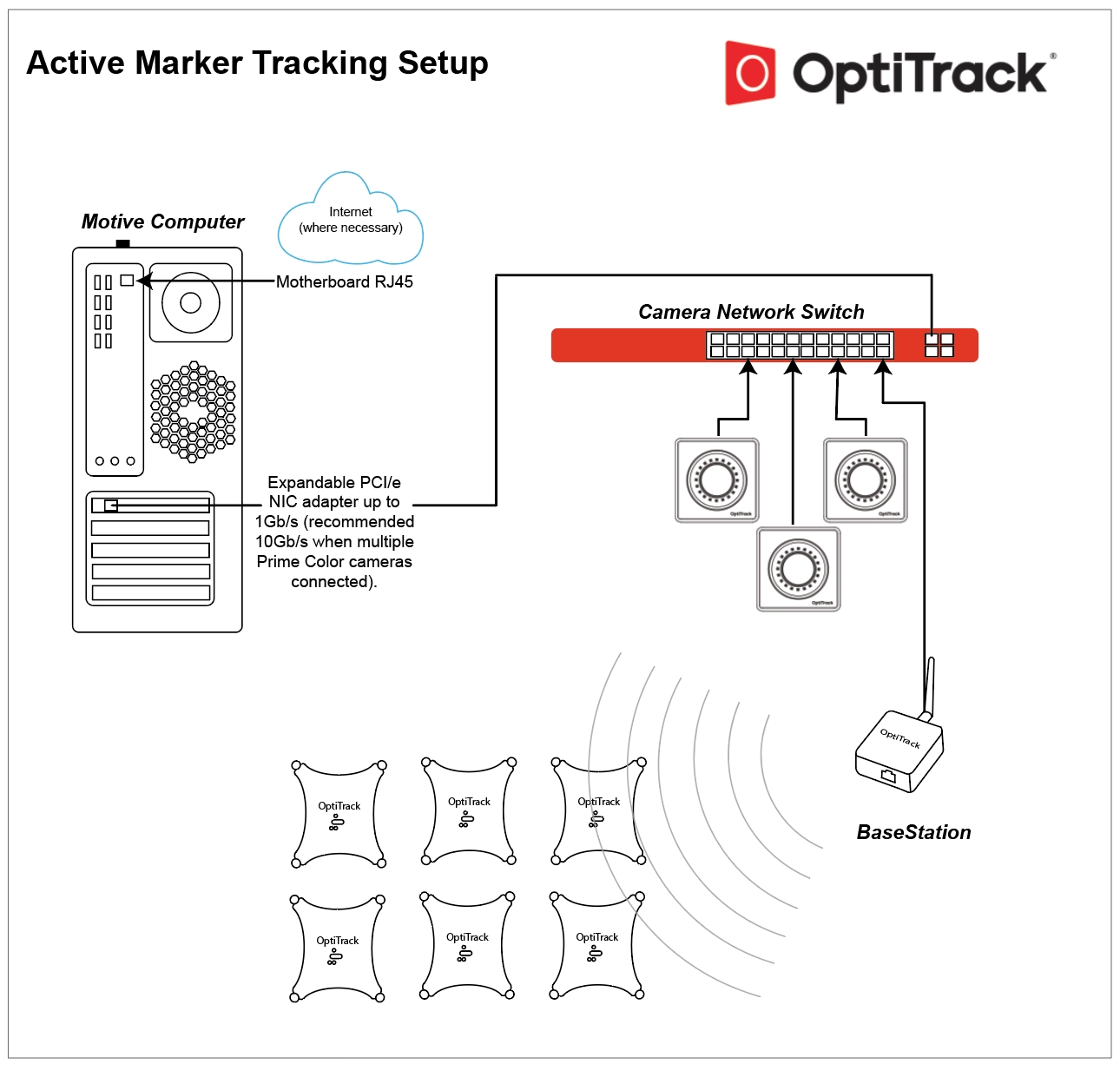
The OptiTrack Active Tracking solution allows synchronized tracking of active LED markers using an OptiTrack camera system. Consisting of a BaseStation and one or more active devices such as the "users choice" Active Tags that can be integrated in to any object, the Active Puck which can act as its own single Rigid Body, or the CinePuck, designed to support Virtual Production and broadcast studios.
The BaseStation emits RF signals to the active markers, allowing precise synchronization between camera exposure and illumination of the LEDs. Each active marker is uniquely labeled in Motive, allowing more stable Rigid Body tracking since active markers will never be mislabeled and unique marker placements are no longer required for distinguishing multiple Rigid Bodies.
To configure assets that contain active tags and an Inertial Measurement Unit (IMU) such as Pucks and CinePucks, please refer to the article IMU Sensor Fusion.
Notes:
This guide is for OptiTrack active markers only. Third-party IR LEDs will not work with the instructions provided on this page.
This solution is supported only with Ethernet camera systems (Slim 13E or Prime series cameras). USB camera systems are not supported.
Active Tracking works with Motive versions 2.x or 3.1 and above. It is not available in version 3.0.
This guide covers active component firmware versions 1.0 and above, which includes all active components that were shipped after September 2017. For active components shipped prior to September 2017, please see the compatibility notes page for more information about firmware compatibility.
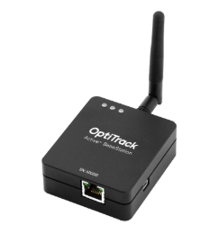
Emits radio frequency signals to synchronize the active markers.
Powered by PoE, connected directly via Ethernet cable to one of the switches in the camera network.
Please see the BaseStation page for product specifications and more information.
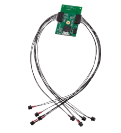
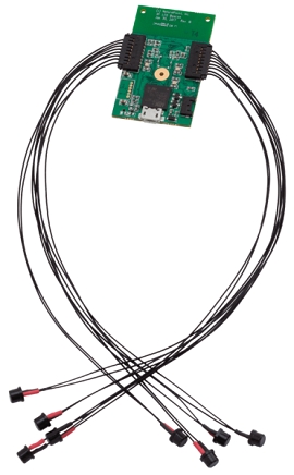
Connects to a USB power source to illuminate the active LEDs.
Receives RF signals from the Base Station and synchronizes illumination of the connected active LED markers accordingly.
LEDs come in bundles of 4. One or two bundles can be connected to each tag, for a maximum of 8 Active LEDs per Tag.
Each LED emits 850 nm IR light.
Size: 5 mm (T1 ¾) Plastic Package, half angle ±65°, typ. 12 mW/sr at 100mA
Please see the page Information for Assembling the Active Tags for more information.
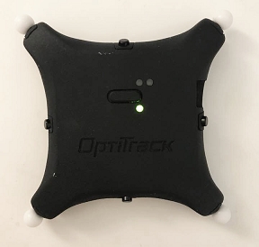
An active tag self-contained into a trackable object, the Active Puck provides 6 DoF information for any object to which it's attached. Pucks include a factory installed Active Tag with 8 LEDs and a rechargeable battery with up to 10-hours of run time on a single charge.
For product specifications and other information about the Puck, please see the page Active Puck.
To configure Pucks that contain an Inertial Measurement Unit (IMU), please refer to the page IMU Sensor Fusion.
Similar to the Active Puck, the CinePuck is designed to attach to a movie camera to support In-Camera Virtual Effects, often referred to as InCam VFX or ICVFX. Please see the page Unreal Engine: OptiTrack InCamera VFX for more information.
For product specifications and other information about the CinePuck, please see the page CinePuck.
All CinePucks contain an Inertial Measurement Unit (IMU). Please refer to the page IMU Sensor Fusion for instructions to configure the CinePuck.
Active tracking is supported only with an Ethernet camera system (Prime series or Slime 13E cameras). For instructions on how to set up a camera system, please refer to the Ethernet Camera Network Setup chapter.
Connect the BaseStation to one of the PoE switches within the camera network.
Metal and other dense materials can cause interference that may reduce the BaseStation's range. For best performance, place the base station near the center of the tracking space, with unobstructed lines of sight to the areas where the Active Tags will be located during use.
Do not place external electromagnetic or radiofrequency devices near the Base Station.
When Base Station is working properly, the LED closest to the antenna should blink green when Motive is running.
The number of Active Devices that can attach to a a single BaseStation is determined by the system frame rate and the divisor applied to the BaseStation. The BaseStation Load Capacity table on the BaseStation page shows the IMU maximum for common frame rates and divisors.
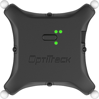
BaseStation LEDs
Communication Indicator LED: When the BaseStation is successfully sending data and communicating with the Active Pucks, the LED closest to the antenna will blink green. If this LED turns red, it indicates that the BaseStation failed to establish a connection with Motive.
Interference Indicator LED: The middle LED indicates if there are other signal-traffics on the respective radio channel and PAN ID that might be interfering with the active components. This LED should stay dark in order for the active marker system to work properly. If it flashes in red, consider switching both the channel and PAN ID on all of the active components.
Power Indicator LED: The LED located at the corner indicates power for the BaseStation. This LED may be disabled on BaseStations with the latest firmware, but on older BaseStations this LED may light up in red to indicate the device has power.
Connect two sets of active markers (4 LEDs in each set) into a Tag.
Connect the battery and/or a micro USB cable to power the Tag. The Tag takes 3.3V ~ 5.0V of inputs from the micro USB cable. If powering with a battery, use only the batteries supplied by OptiTrack. To recharge the battery, connect it to the Tag then connect the micro USB cable to a power source.
To initialize the Tag, press the power switch once. Be careful not to hold down on the power switch for more than a second, as this will initialize the device in the firmware update (DFU) mode. If it initializes in the DFU mode, which is indicated by two orange LEDs, just power off and restart the Tag. To power off the Tag, hold down on the power switch until the status LEDs go dark.
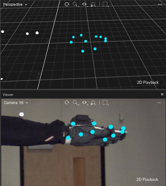
Once powered, you should be able to see the illumination of IR LEDs from the 2D reference camera view.
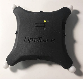
Puck Setup
Press the power button for 1~2 seconds and release to power the device on.
The top-left LED will turn amber while the Puck initializes. The bottom LED will turn green when the Puck has made a successful connection with the BaseStation, at which point the top-left LED will start blinking green to indicate the sync packets are being received.
For more information, please read the Active Puck page.
As shipped, BaseStations and active devices will connect to the OptiTrack system without additional configuration by the user. Some circumstances may require a configuration update, such as when adding new BaseStations to an existing system or to change the RF channel or BaseStation divisor rate.
The BaseStation is configured outside of Motive, using one of the following programs:
Please see the linked pages for more details on configuring the BaseStation.
The following settings are relevant to Active Tracking.
Settings → Live Pipeline → Solver Tab -> Trajectorizer
Default value: 12
This setting adjusts the complexity of the illumination patterns produced by active markers.
In most applications, the default value is sufficient for high quality tracking results. If a large number of Rigid Bodies are tracked simultaneously, increase the value to allow more combinations of illumination patterns on each marker.
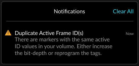
If this value is set too low, duplicate active IDs can be produced, should this error appear increase the value of this setting.
Default value: 3
This sets the number of rays required to establish the active ID for each on frame of an active marker cycle.
The default value works well for the majority of applications. If this value is increased and active markers become occluded, it may take longer to reestablish those markers in the Motive 3D Viewport.
Settings → Views → 3D Tab -> Markers
The Markers section sets the default color assigned to different types of markers. Markers that are part of an asset will use the color selected in the visuals section of the Asset Properties.
Default color: blue
The Active setting distinguishes active markers from passive in the Motive 3D Viewport.
Default color: white
Intermediate markers are active markers in a temporary state prior to being identified in Motive. These markers change to the active marker color (or the asset color, if different) once Motive identifies them.
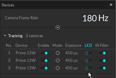
The following camera settings yield the best tracking results for active LED markers.
Set the camera exposure a bit higher than you would when tracking passive markers. This allows the cameras to better detect the active markers. The optimal value will vary depending on the camera system setup, but in general, set the camera exposure between 400 ~ 750, microseconds.
When tracking active markers only, the cameras do not need to emit IR lights. In this case, you can disable the LED lights in the Devices pane.
Information about BaseStations and Active Tags is available in the Devices pane. Select an item in the Devices pane to view its properties in the Properties pane. All values are read-only.
BaseStations are listed in the Synchronization category of the Devices pane. Available display options are the Device (device type) and the Serial number.
The Active Batch Programmer is required to view additional settings or make configuration changes to a Base Station and its associated active devices.
Active devices that connect to the camera system via BaseStations are listed in the Active Tag section. The following properties are available:
Name: the tag name consists of two numbers, the the RF channel used to communicate with the Base Station followed by the unique Uplink ID assigned to the device.
Paired Asset: If the tag is paired to an asset, the asset's name will appear here. Otherwise, the field will display N/A.
Aligned: shows the status of the Active tag.
BaseStation: displays the serial number of the connected BaseStation. This column is not displayed by default; right-click the header to add it.
Active Markers are reconstructed and tracked in Motive automatically. The unique illumination pattern ensures each active marker is individually labeled, with an Active ID assigned to the corresponding reconstruction. This applies whether or not the Active Marker is part of an asset.
The Active IDs can be monitored in the 3D Viewport as part of the marker label, in both Live and Edit modes. To view:
Enable the Marker Labels and the Active ID options.
Active IDs that are not part of an asset:
The same Active IDs after asset creation:
Rigid body definitions created using Active Markers will search for specific Active IDs along with the marker placements to track the Rigid Body. See below for more details.
Duplicate active frame IDs
This Notification displays if more than one marker has the same ID. Duplicate IDs may cause errors during 3D reconstruction.
If this occurs, please contact support for assistance.
As noted above, rigid body definitions created from reconstructions with Active IDs will search for those IDs to solve the Rigid Body. This means active markers can be placed in perfectly symmetrical marker arrangements across multiple Rigid Bodies without the risk of labeling swaps.
For more information, please see the following pages:
To create or modify a Rigid Body asset, please see Rigid Body Tracking.
To configure Pucks and CinePucks with IMU sensors, please see IMU Sensor Fusion.
This page reviews the active finger marker set and how to set it up.
The active finger Marker Set utilizes the tracking capability of active markers and the active labeling features to accomplish tracking of both the hands and the fingers. These Marker Sets require the tracking solution and a set of Tag(s). Wired from an active Tag, each active marker must attach to the expected locations. For each hand, 8 active markers are needed, with 2 passive markers attached at the wrist.
Manus VR Gloves
Alternatively, you can also use Manus VR Gloves for tracking the fingers. For more information, refer to the page.
The Active BaseStation
Active Tag(s) with active markers.
A way to attach active markers onto the hands (e.g., gloves).
Baseline + Active Fingers (57)
Core + Active Fingers (62)
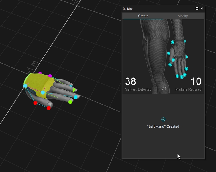
Right Hand + Active Fingers (10)
Left Hand + Active Fingers (10)
Please note that the numbers listed in the Marker Set names are the total number of markers needed, including both active and passive markers.
Total of 10 markers will be attached on each hand (8 Active markers and 2 passive).
Tags: Attach Tags to each hand for the active LEDs.
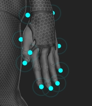
Passive Markers (2): Attach the 2 passive markers to both sides of the wrist, directly on the joints of either side along the wrist flexion point.
Active Markers (8): Each Tag connects up to 8 active markers. Position the wired active markers at the tip of all five fingers (5), one each on the knuckle of the index finger and the pinky finger (2), and place the remaining active marker on the inside of the bottom thumb joint.
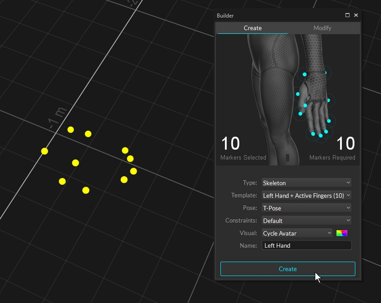
Steps for creating an active finger Marker Set is the same as the other skeleton Marker Set:
Make sure all of the markers are placed in the correct positions. For the Core + Active Fingers (62) Marker Set, please make sure the passive full body tracking markers are also placed on the person's body.
Select the finger markers in the 3D viewport.
Click Create.
Use the Application Settings panel to customize Motive and set default values. Application Settings can be accessed from the View menu or by clicking the icon on the main toolbar.
If the tag is unpaired, the circle x icon will appear.
If the tag is pairing, the circle with the wave icon will appear.
If the tag is paired, the green circle with green check icon will appear.
Click the in the 3D Viewport to open the Visual Aids menu.
Open the and select the desired hand Marker Set under the drop-down menu.
Once the markers have been placed, ask the subject to strike the .
The Marker Detected must match Marker Required in the .