
Loading...
Loading...
Loading...
Loading...
Loading...
Loading...
Loading...
Loading...
In Motive, the Application Settings can be accessed under the View tab or by clicking icon on the main toolbar.
Default Application Settings can be recovered by Reset Application Settings under the Edit Tools tab from the main Toolbar.
The Application Settings consists of several tabs, all of which we'll go into further details on their respective pages. Below is the list of the Application Settings tabs in Motive 2.3.
Cameras
The real-time reconstruction settings can be accessed in the Reconstruction tab under the Application Settings pane.
Reconstruction in motion capture is a process of deriving 3D points from 2D coordinate information obtained from captured images, and the Point Cloud is the core engine that runs the reconstruction process. The reconstruction settings define the parameters of the point cloud engine, and they can be modified to optimize the acquisition of 3D data points.
For more information on how to utilize the reconstruction settings, visit page.
The Point Cloud reconstruction engine converts two-dimensional point from camera images into coordinates in a three-dimensional space through triangulation. All cameras should be calibrated for the engine to function properly (see ). The triangulation of a marker occurs when a minimum of 2 rays intersect. Rays are generated from the objects present on a camera image and they resolve into a 3D point when the conditions defined by the reconstructions settings are met. These rays can be seen from the when the tracked rays and untracked rays are enabled from the visibility settings.
Due to inherent errors in marker tracking, rays generally do not converge perfectly on a single point in 3D space, so a tolerance value is defined. This tolerance, called the residual, represents one of the reconstruction constraints. If a ray could be defined as an infinite series of points aligned in a straight line, two or more rays that have points within the defined residual range (in mm) will form a marker.
Enable Point Cloud Reconstruction
Default: ON
This toggles on and off. It is recommended to turn this off if computer resource need to be dedicated to 2D recording. When disabled, you will not be able to see 3D data from the Live mode nor from the recorded 2D data.
Default: 10.00 mm
The residual value sets the maximum allowable offset distance (in mm) between rays contributing to a single 3D point.
When the residual value is set too high, unassociated marker rays may contribute to marker reconstruction, and non-existing ghost markers may be reconstructed. When this value is set too low, the contributing rays within a marker could reconstruct multiple markers where there should only be one.
Choosing a good Residual Value
Depending on the size of markers used, the contributing rays will converge with a varying tolerable offset. If you are working with smaller markers, set the residual value lower. If you're working with larger markers, set this value higher because the centroid rays will not converge as precisely as the smaller markers. A starting point is to set the residual value to the diameter of the smallest marker and go down from there until you start seeing ghost markers. For example, when 3 mm and 14 mm markers are captured in a same volume, set the residual value to less than 3 mm. The ghost markers can appear on larger markers if this value is set too low.
The residual can also be viewed as the minimum distance between two markers before they begin to merge. If two markers have a separation distance smaller than the defined residual (in mm), the contributing rays for each marker will be merged and only one marker will be reconstructed, which is undesirable. Remember that for a 3D point to be reconstructed, it needs to have at least two rays contributing to a marker depending on the setting.
If calibration quality is not very good, you may need to set this value higher for increased tolerance. This will work only if your markers are further apart in the 2D views throughout the given marker motion. This is because there is more errors in the system. However, for best results, you should always work with a calibration with minimal error (See ).
Default: None — the calibration solver will set a suggested distance based on the wanding results, but this can still be adjusted by the user after calibration.
This sets the maximum distance, in meters, a marker can be from the camera to be considered for 3D reconstruction. In very large volumes with high resolution cameras, this value can be increased for a longer tracking range or to allow contributions from more cameras in the setup. This setting can also be reduced to filter out longer rays from reconstruction. Longer rays generally produce less accurate data than shorter rays.
When capturing in a large-size volume with a medium-size – 20 ~ 50 cameras – camera system, this setting can be adjusted for better tracking results. Tracking rays from cameras at the far end of the volume may be inaccurate for tracking markers on the opposite end of the volume, and the unstable rays may contribute to ghost marker reconstructions. In this case, lower the maximum ray length to restrict reconstruction contributions from cameras tracking at long distances. For captures vulnerable to frequent marker occlusions, adjusting this constraint is not recommended since more camera coverage is needed for preventing the occlusions. Note that lowering this setting can take a toll on performance at higher camera counts and marker counts because the solver has to perform numerous calculations per second to decide which rays are good.
Default: 0.2 m
This sets the minimum distance, in meters, between a marker and a camera for the camera to contribute to the reconstruction of the marker. When ghost markers appear close to the camera lens, increase this setting to restrict the unwanted reconstructions in the vicinity. But for close-range tracking applications, this setting must be set low.
Default: 2 rays
This sets the required minimum number of cameras that must see a marker for it to be reconstructed.
For a marker to be reconstructed, at least two or more cameras need to see the marker. The minimum rays setting defines the required number of cameras that must see a marker for it to be reconstructed. If you have 4 cameras and set this to 4, all cameras must see the marker; otherwise, the marker will not be reconstructed and the contributing rays will become the untracked rays.
When more rays are contributing to a marker, more accurate reconstruction can be achieved, but generally, you don't need all cameras in a setup to see a marker. If you have a lot of cameras capturing a marker, you can safely increase this setting to prevent false reconstructions which may come from 2 or 3 rays that happen to connect within the residual range. However, be careful when increasing this setting because a high number of minimum rays requirement may decrease the effective capture volume and increase the frequency of marker occlusions during capture.
Default: Passive
Configures Motive for tracking either the passive markers, the synchronized active markers, or both. See for more information.
Default: 12
This setting is available only if marker labeling mode is set to one of the active marker tracking modes. This setting sets the complexity of the active illumination patterns. When tracking a high number of rigid body, this may need to be increased to allow for more combinations of the illumination patterns on each marker. When this value is set too low, the active labeling will not work properly.
Default: Disabled
Enable or disable continuous calibration. When enabled, Motive will continuously monitor the calibration quality and update it as necessary. For more information, refer to the page.
Default: 4
This setting enables the Ray Ranking, which calculates quality of each ray to potentially improve the reconstruction. Setting this to zero means that ray ranking is off, while 1 through 4 set the number of the evaluation iterations; 4 being 4 iterations. Setting this value to the max of 4 will slow down the reconstruction process but will produce more accurate results.
The Ray Ranking increases the stability of the reconstruction but at a heavy performance cost. The ray quality is analyzed by comparing convergence of rays that are contributing to the same marker. An average converging point is calculated, and each ray is ranked starting from the one closest to the converging point. Then, each ray is weighed differently in the Point Cloud reconstruction engine according to the assigned rankings.
This setting is useful especially when there are multiple rays contributing to a marker reconstruction. If you're working with small to medium marker counts, enabling this will not have an evident improvement on performance. Also, when precise real-time performance is required, disable this setting especially for a setup with numerous cameras.
Default: 0 pixels
Establishes a dead zone, in pixels, around the edge of the 2D camera image. Any 2D objects detected within this gutter will be discarded before calculating through the point cloud. In essence, it is a way of getting only the best data of the captured images, because markers seen at the edges of the camera sensor tend to have higher errors.
This setting can be increased in small amounts in order to accommodate for cases where lens distortions are potentially causing problem with tracking. Another use of the setting for limiting the amount of data going to the reconstruction solver, which may help when you have a lot of markers and/or cameras. Be careful adjusting this setting as the trimmed data can't be reacquired in post-processing pipelines.
Default: 5 degrees
The minimum allowable angle – in degrees from the marker's point of view – between the rays to consider them valid for marker reconstruction. This separation also represents the minimum distance required between the cameras. In general, cameras should be placed with enough distance in between in order to capture unique views on the target volume. For example, if there are only two cameras, an ideal reconstruction would occur when the cameras are separated far enough so the rays converge with a 90 degree of an incident angle from the perspective of the reconstructed marker(s).
When working with a smaller-sized system with a fewer number of cameras, there will be only a limited number of markers rays that can be utilized for reconstruction. In this case, lower this setting to allow reconstruction contributions from even the cameras that are in close vicinity to each other.
On the other hand, when working with a large system setup with a lot of cameras, you can set this value a bit higher to limit marker rays that are coming from the cameras that are too close together. Similar vantages obtained by the cameras within vicinity do not necessarily contribute unique positional data to the reconstruction, but they only increase the required amount of computation. Rays coming from very close cameras may increase the error in the reconstruction. Better reconstruction can only be achieved with a good, overall camera coverage (See ).
Default: False
When the Rigid Body Marker Override is set to True, Motive will replace observed 3D markers with the rigid body's solution for those markers. 3D tracking data of reconstructed and labeled trajectories will be replaced by the expected marker locations of the corresponding rigid body solve.
This is applicable only for rigid bodies using , and when the Use Smart Markers is enabled.
Default: True
When this feature is enabled, Motive uses expected marker locations from both the model solve and the trajectory history to create virtual markers. These virtual markers are not direct reconstructions from the Point Cloud engine. When the use of smart markers is enabled, rigid body and skeleton asset definitions will also be used in conjunction with 2D data and reconstructed 3D data to facilitate reconstruction of additional 3D marker locations to improve tracking stability. These virtual markers are created to make live data match recorded data in situations where model and history data helped to improve the live solve
More specifically, for rigid body tracking, Motive will utilize untracked rays along with the rigid body asset definition to replace the missing markers in the 3D data. In order to compute these reconstructions, the rigid body must be using the tracking algorithm. For skeleton tracking, only the asset definitions are used to approximate virtual reconstruction at the location where the occluded marker was originally expected according to the corresponding skeleton asset.
Using the asset definitions in obtaining the 3D data could be especially beneficial for accomplishing stable tracking of the assets in low camera count systems where all of the reconstructions may not always meet the minimum required tracked ray requirements.
Usage note. In 2.0, trajectories of virtually created markers on a skeleton segment may not get plotted on the graph view pane.
Default: true
When set to true, Motive will recognize the unique illuminations from synchronized active markers and perform active labeling on its reconstructions. If you are utilizing our active marker solution, this must be set to true. For more information about active labeling, read through the page.
Default: 20
Sets the required minimum number of frames without occlusion for a tracked marker to be recognized as the same reconstruction to form a trajectory. If a marker is hidden, or occluded, longer than the defined number of frames, then the trajectory will be truncated and the marker will become unlabeled.
Default: 0.06 m
To identify and label a marker from one frame to the next, a prediction radius must be set. If a marker location in the subsequent frame falls outside of the defined prediction radius, the marker will no longer be identified and become unlabeled.
For capturing relatively slow motions with tight marker clusters, limiting the prediction radius will help maintaining precise marker labels throughout the trajectory. Faster motions will have a bigger frame to frame displacement value and the prediction radius should be increased. When capturing in a low frame rate settings, set this value higher since there will be bigger displacements between frames.
Bound Reconstrutction
(Default: False) When set to true, the 3D points will be reconstructed only within the given boundaries of the capture volume. The minimum and maximum boundaries of X/Y/Z axis are defined in the below properties.
Visible Bounds
Visualize the reconstruction bounds in the .
Bounds Shape
(Default: Cuboid) This setting selects the shape of the reconstruction bound. You can select from cuboid, cylinder, spherical, or ellipsoid shapes and the corresponding size and location parameters (e.g. center x/y/z and width x/y/z) will appear so that the bound can be customized to restrict the reconstruction to a certain area of the capture volume.
After markers have been reconstructed in Motive, they must be labeled. Individual markers can be manually labeled, but the auto-labeler simplifies this process using the . Rigid body and skeleton assets, created in Motive, saves their marker arrangement definitions and uses them to auto-label corresponding marker sets within the Take. The , is a process of associating 3D marker reconstructions in multiple captured frames by assigning marker labels within the defined constraints. After the labeling process, each of the labeled markers provides respective 3D trajectories throughout the Take.
Pose Detection
Default: TruePose detection improves the stability of skeleton tracking by detecting standing poses. For multi-skeleton captures, this feature may increase the skeleton solve latency.
Minimum Key Frames
Default: 2This setting sets the required minimum number of frames for each trajectory in the recorded 3D data. Any trajectories with a length less than the required minimum will be discarded from the 3D data after running the auto-labeling pipeline.
Auto-labeler Passes
Default: 1The number of iterations for analyzing detected marker trajectories for maintaining constant marker labels. Increasing this setting can improve the marker auto-labeling, but more iterations will require more time and computation effort to complete the auto-labeling.
Rigid Body Assisted Labeling can be used to optimize the labeling of markers within a region defined by a rigid body. The first step in using this feature is to create a rigid body from markers that are visible and rigidly connected. The example shown in the figure below demonstrates this for hand tracking. Five white markers are selected on the top of the wrist - which is rigidly defined. The black markers on the fingers are not rigidly defined in any fashion but are within the boundary of the Rigid Body Assisted Labeler. Labeling continuity is improved for the markers on the fingers which are given automatic labels.Tracking of organic or flexible objects - that do not have a tracking models like the face and hand, are good candidates for Rigid Body Assisted Labeling.
Rigid Body-Assisted Labeling
Default: FalseEnable or disable rigid body assisted labeling feature.
Rigid Body Volume Radius
Default: 300 mmThe rigid body volume radius defines the region of space where the rigid body assisted labeling is applied. Increasing this radius will increase time needed for the auto-labeling so care should be made when setting this property.
Prediction Radius (mm)
Default: 10 mmThe prediction radius defines the size of the bounding region used to label markers. When labeling a marker from one frame to the next, a bounding region, relative to the rigid body, is created around each labeled marker. The labeling continuity is restricted to the bounding region from frame to frame. Increasing this can allow markers to swap if there are occlusions in the data. Decreasing this restricts labeling from frame to frame but may lead to an increase in broken trajectories.
Maximum Assisted Labeling Gap
Default: 30 framesThe maximum gap frames property defines the maximum number of frames a marker can be hidden before it is truncated or unlabeled. Increase this value if larger gaps are to be anticipated. Increasing the assisted labeling gap will increase the processing time of reconstruction.
Discard External Markers
Default: FalseDiscards markers outside of rigid body volume. Enabling this property will eliminate marker reconstructions outside of the region defined by the Rigid Body Volume.
Dynamic Constraints
Default: NonePrevents the rigid body from moving/rotation more than specified amount per frame.
Max Translation (mm)
Default: 100Distance for Dynamic Translation Constraint option.
Max Rotation (deg)
Default: 30Angle for the Dynamic Rotation Constraint option.
Minimum Tracking Frames
Default: 20Dynamic constraints are enabled when the rigid body is consecutively tracking more than this frame count.
Marker Filter Diameters
Default: FalseMarkers less than this diameter will not be used for rigid body tracking.
Minimum Diameter (mm)
Default: 10Diameter used for Marker Filter Diameter option.
A list of the default rigid body creation properties is listed under the Rigid Bodies tab. Thes properties are applied to only rigid bodies that are newly created after the properties have been modified. For descriptions of the rigid body properties, please read through the Properties: Rigid Body page.


A list of the default Skeleton display properties for newly created skeletons is listed under the Skeletons tab. These properties are applied to only skeleton assets that are newly created after the properties have been modified. For descriptions of the skeleton properties, please read through the Properties: Skeleton page.
Skeleton Creation Pose
Chooses which Skeleton calibration pose to be used for creation. (T-pose, A-pose Palms Downward, A-pose Palms Forward, and A-pose Elbows Bent)
Head Upright
Creates the skeleton with heads upright irrespective of head marker locations.
Straight Arms
Creates the skeleton with arms straight even when arm markers are not straight.
Straight Legs
Creates the skeleton with straight knee joints even when leg markers are not straight.
Feet On Floor
Creates the skeleton with feet planted on the ground level.
Height Marker
Force the solver so that the height of the created skeleton aligns with the top head marker.
The Assets tab in the application settings panel is where you can configure the creation properties for Rigid Body and Skeleton assets. In other words, all of the settings configured in this tab will be assigned to the Rigid Body and Skeleton that are newly created in Motive.
A list of the default Rigid Body creation properties is listed under the Rigid Bodies tab. These properties are applied to only Rigid Bodies that are newly created after the properties have been modified. For descriptions of the Rigid Body properties, please read through the page.
You can change the naming convention of Rigid Bodies when they are first created. For instance, if it is set to RigidBody, the first Rigid Body will be named RigidBody when first created. Any subsequent Rigid Bodies will be named RigidBody 001, RigidBody 002, and so on.
User definable ID. When streaming tracking data, this ID can be used as a reference to specific Rigid Body assets.
The minimum number of markers that must be labeled in order for the respective asset to be booted.
The minimum number of markers that must be labeled in order for the respective asset to be tracked.
Applies double exponential smoothing to translation and rotation. Disabled at 0.
Compensate for system latency by predicting movement into the future.
Toggle 'On' to enable. Displays asset's name over the corresponding skeleton in the 3D viewport.
Select the default color a Rigid Body will have upon creation. Select 'Rainbow' to cycle through a different color each time a new Rigid Body is created.
When enabled this shows a visual trail behind a Rigid Body's pivot point. You can change the History Length, which will determine how long the trail persists before retracting.
Shows a Rigid Body's visual overlay. This is by default Enabled. If disabled, the Rigid Body will only appear as individual markers with the Rigid Body's color and pivot marker.
When enabled for Rigid Bodies, this will display the Rigid Body's pivot point.
Shows the transparent sphere that represents where an asset first searches for markers, i.e. the asset model marker.
When enabled and a valid geometric model is loaded, the model will draw instead of the Rigid Body.
Allows the asset to deform more or less to accommodate markers that don't fix the model. High values will allow assets to fit onto markers that don't match the model as well.
A list of the default Skeleton display properties for newly created Skeletons is listed under the Skeletons tab. These properties are applied to only Skeleton assets that are newly created after the properties have been modified. For descriptions of the Skeleton properties, please read through the page.
Creates the Skeleton with arms straight even when arm markers are not straight.
Creates the Skeleton with straight knee joints even when leg markers are not straight.
Creates the Skeleton with feet planted on the ground level.
Creates the Skeleton with heads upright irrespective of head marker locations.
Force the solver so that the height of the created Skeleton aligns with the top head marker.
Height offset applied to hands to account for markers placed above the write and knuckle joints.
Same as the Rigid Body visuals above:
Label
Creation Color
Bones
Asset Model Markers
Changes the color of the skeleton visual to red when there are no markers contributing to a joint.
Display Coordinate axes of each joint.
Displays the lines between labeled skeleton markers and corresponding expected marker locations.
Displays lines between skeleton markers and their joint locations.
In Motive, the Application Settings can be accessed under the View tab or by clicking icon on the main toolbar.
Default Application Settings can be recovered by Reset Application Settings under the Edit Tools tab from the main Toolbar.
Reconstruction tab contains a list of parameters for the real-time Point Cloud reconstruction engine.
Reconstruction in motion capture is a process of deriving 3D points from 2D coordinate information obtained from captured images, and the Point Cloud is the core engine that runs the reconstruction process. The reconstruction settings in the Application Settings modifies the engine's parameters for real-time reconstructions. These settings can be modified to optimize the quality of reconstructions in Live mode depending on the conditions of the capture and what you're trying to achieve. Use the to live-monitor the reconstruction outcomes from the configured settings.
Take Suffix Format String
Sets the separator (_) and string format specifiers (%03d) for the suffix added after existing file names.
Numeric LEDs
Enable or disable the LED panel in front of cameras that displays assigned camera numbers.
Auto Archive Takes
Enable/Disable auto-archiving of Takes when
Save Data Folder
Motive persists all of the session folders that are imported into the pane so that the users don't have to re-import them again after closing out of the application. If this is set to false, the session folders will no longer be persisted, and only the default session folder will always be loaded.
Restore Calibration
Automatically loads the previous, or last saved, calibration setting when starting Motive.
Camera ID
Sets how Camera IDs are assigned for each camera in a setup. Available options are By Location and By Serial Number. When assigning by location, camera IDs will be given following the positional order in clockwise direction, starting from the -X and -Z quadrant in respect to the origin.
Device Profile
Sets the default device profile, XML format, to load onto Motive. The device profile determines and configures the settings for peripheral devices such as force plates, NI-DAQ, or navigation controllers.
Switch to MJPEG
Configures the Aim Assist button. Sets whether the button will switch the camera to MJPEG mode and back to the default camera group record mode. Valid options are: True (default) and False.
Aiming Crosshairs
Sets whether the camera button will display the aiming crosshairs on the MJPEG view of the camera. Valid options are True (default), False.
Aiming Button LED
Enables or disables LED illumination on the Aim Assist button behind Prime Series cameras.
Controls the color of the (Prime Series cameras only). Options include distinct indications for Live, Recording, Playback, Selection and Scene camera statuses, and you can choose the color for the corresponding camera status.
Live Color
(Default: Blue) Sets the indicator ring color for cameras in Live mode. Default: Blue
Recording Color
(Default: Red) Sets the indicator ring color for cameras when recording a capture.
Playback Color
(Default: Black) Sets the indicator ring color for cameras when Motive is in playback mode.
Selection Color
(Default: Yellow) Sets the indicator ring color for cameras that are selected in Motive.
Scene Camera
(Default: Orange) Sets the indicator ring color for cameras that are set as the reference camera in Motive.
LLDP (PoE+) Detection
Enables detection of PoE+ switches by High Power cameras (Prime 17W and Prime 41). LLDP allows the cameras to communicate directly with the switch and determine power availability to increase output to the IR LED rings. When using Ethernet switches that are not PoE+ Enabled or switches that are not LLDP enabled, cameras will not go into the high power mode even with this setting enabled.
Strobe On During Playback
Keeps the camera IR strobe on at all times, even during the playback mode.


This section of the application settings is used for configuring the properties for all of the cameras in the tracking group. The settings include display options, masking properties, but most importantly, the 2D Filter settings for the camera system which basically determines which reflections are considered as marker reflections from the camera view.
When a frame of image is captured by a camera, the 2D Object Filter is applied. By judging on sizes and shapes of the detected reflections, this filter determines which of them can be accepted as marker reflections. Parameters for the 2D Object filter are configured in the Devices pane under the Filters section.
Filter Type
Default: Size and RoundnessToggles 2D object (Size and Roundness) filtering on or off.This filter is very useful for filtering out extraneous reflections according to their characteristics (size and roundness) rather than blocking pixels using the masking tool or the Block Visible feature. Turn off this setting only when you want to use every 2D pixels above the brightness threshold from camera views. When there are extraneous or flickering reflections in the view, turn on the filter to specify and consider reflections only from markers. There are multiple filtering parameters to distinguish the marker reflections. Given that there are assumed marker characteristics, filtering parameters can be set. The size parameters can be defined to filter out extra-small or extra-large reflections that are most likely from extraneous sources other than markers. Non-circular reflections can be ignored assuming that all reflective markers have circular shapes. Note that even when applying the size and roundness filter, you should always Block Visible when you calibrate.
Min Thresholded Pixels (pixels)
Default: 4 pixelsThe minimum pixel size of a 2D object, a collection of pixels grouped together, for it to be included in the Point Cloud reconstruction. All pixels must first meet the brightness threshold defined in the Cameras pane in order to be grouped as a 2D object. This can be used to filter out small reflections that are flickering in the view. The default value for the minimum pixel size is 4, which means that there must be 4 or more pixels in a group for a ray to be generated.
Max Thresholded Pixels (pixels)
Default: 2000 pixelsThe maximum size of a 2D object, in pixels, in order for it to be included in point cloud reconstruction. Default is 2000 pixels which basically means that all of detected large reflections smaller than 2000 pixel-size will be included as a 2D object. Use this to filter out larger markers in a variable marker capture. For instance, if you have 4 mm markers on an actor's face and 14 mm markers on their body, use this setting to filter out the larger markers if the need arises.
Circularity
Default: 0.6This setting sets the threshold of the circularity filter. Valid range is between 0 and 1; with 1 being a perfectly round reflection and 0 being flat. Using this 2D object filter, the software can identify marker reflections using the shape, specifically the roundness, of the group of thresholded pixels. Higher circularity setting will filter out all other reflections that are not circular. It is recommended to optimize this setting so that extraneous reflections are efficiently filtered out while not filtering out the marker reflections. When using lower resolution cameras to capture smaller markers at a long distance, the marker reflection may appear to be more pixelated and non-circular. In this case, you may need to lower the circularity filter value for the reflection to be considered as a 2D object from the camera view. Also, this setting may need to be lowered when tracking non-spherical markers in order to avoid filtering the reflections.
Intrusion Band
Default: 0.5 (Pixels)The intrusion band feature allows cameras to recognize reflections that are about to be merged and filter them out before it happens. This filter occurs before the circularity filter, and these reflections are rejected before the thresholded pixels merge. This is useful for improving the accuracy of the tracking, because bright pixels from close by reflections may slightly shift the centroid locations. The intrusion band value is added to the calculated radius of detected markers to establish a boundary, and any extraneous reflections intruding the boundary is considered as the intrusion and gets omitted. When an intrusion happens, both intruding reflection and detected marker reflection will be filtered out.
Garyscale Floor
Default: 48The grayscale floor setting further darkens pixels with lower brightness intensity values.
Object Margin
Default: 2 (Pixels)The object margin adds an additional margin on top of the intrusion band for filtering out merged reflections. Lowering this value will better detect close-by reflections, but may decrease the accuracy of the centroid positions as a tradeoff.
Name
Sets the name for the selected camera group.
Camera Color
Sets the color for camera group members as they appear in the 3D viewport. Color values are input as standard RGB triplets.
Visible Cameras
Selects whether cameras in the group are displayed in the viewport.
Show All Color Camera
By default, only the cameras that are equipped with the IR filter switcher are shown in the and Prime Color cameras without filter switcher are hidden. When this setting is set to true, all of the Prime Color cameras will show up in the 3D viewport.
Show Capture Volume
Selects whether the capture volume (defined as capable of tracking a single marker) is displayed in the viewport. Enabling this will allow the volume to be displayed as a wire cage around the ground plane where multiple cameras fields of view intersect. Valid options are True, False (default).
Camera Overlap
Sets the minimum camera overlap necessary for a region to be visualized as part of the capture volume. Higher numbers represent more camera coverage, but they will tend to reduce the size of the visualized capture volume. Valid range is 1 to 25 (default 3).
Volume Resolution
Sets the resolution of the capture volume visualization. A higher number represents a more detailed visualization. Valid range is 1 to 120 (default 50).
FOV Intensity
Sets the opacity of the FOV visualization. A higher value represents a more opaque volume visualization. Valid range is 1 to 100 (default 50).
Opacity
Sets the opacity of the volume visualization. A value of 1 is transparent and 100 is opaque. Valid range is 1 to 100 (default 100).
Synchronization Control
Determines how late camera frames are dealt with. Timely Delivery will drop late frames, which is ideal for real-time applications where data completeness is secondary to timeliness. Complete Delivery will hold up processing of frames when a frame is late. Automatic, which is the default and recommended setting, runs in Timely Delivery mode until it gets a non-trivial percentage of late frames, at which point it will automatically switch to Complete Delivery.
Shutter Offset
Delays the shutter timing of selected tracking camera group for N microseconds.
Mask Width (pixels)
Sets the extra pixel coverage (width) for masking visible markers when the mask visible function is used. A larger number will block a wider grouping of pixels simultaneously. Valid range is determined by the resolution of the cameras.
Mask Height (pixels)
Sets the extra pixel coverage (height) for masking visible markers when the mask visible function is used. A larger number will block a wider grouping of pixels simultaneously. Valid range is determined by the resolution of the cameras.
Camera Health Info
Displays various assessments of camera health over the 2D camera views, for troubleshooting performance issues. If any performance issues is detected, corresponding problem will be listed at the bottom of the 2D camera view.
Reticles
When enabled, renders a crosshair on top of the 2D camera views, which can be useful for camera aiming.
Masks
Enables displaying masked area on the 2D camera views, in red.
Backproject Markers
Enables markers selected from the 3D Perspective View to be also highlighted with yellow crosshairs in the 2D camera view, based on calculated position. Crosshairs that are not directly over the marker tend to indicate occlusion or poor camera calibration.
Marker Filter
When enabled, filtered reflections will be labeled with the corresponding in the 2D camera view.
Marker Coordinates
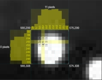
Displays 2D coordinate of the detected object centroids within the captured image, in pixels.
Marker Centroids
Displays crosshairs on marker centroids in the 2D view.
Marker Boundaries
Displays a box around each marker, indicating its calculated edges after the brightness threshold.
Marker Circularity
Displays the roundness of an object. A value of 1 indicates maximum roundness, while a value of 0 indicates no roundness.Pixel inspector enabled in 2D view
Marker Aspect Ratio
Displays the ratio of object width to object height as a decimal, resolved to .01 pixel.
Marker Size
Displays the area of the object in pixels, accurate to .01 pixel.
Marker Label
Displays the pre-identified labels assigned to 2D objects for initial tracking from frame to frame.
Pixel Inspection
Displays X,Y coordinates for cursor location when hovering over a camera, and pixel brightness for selected pixels when a region is drag-selected. Inspecting pixel brightness can be useful during camera focusing, tuning, and aiming.
Texture Streaming
Disables or enables texture streaming of reference videos on the 2D camera viewport.
Visual FPS Target
Sets a maximum frame display rate for the 2D camera view.
Background Color
Selects the color to display in the viewport between camera panes.
Camera Info
Enables text overlay of pertinent camera information on the 2D Multi Camera view panes. Displayed information includes image mode, time, data rate, frame ID, visual FPS, number of objects, camera serial, exposure value, threshold value, IR intensity value, internal temperature, and camera sync mode.
Show Distortion
Displays each camera’s lens distortion map.
Overlay Color
Selects the color of the lens distortion map display.
Overlay Transparency
Selects the transparency percentage for the lens distortion map.
Overlay Resolution
Selects the level of details for displaying the lens distortion. More specifically, it sets number of distortion grids on the width and height of the distortion map.
Show as Predistortion
Selects whether the map is shown as pre-distorted or distorted.
Display Mode
Sets levels of details for the markers displayed in the multi-camera 2D view. Available modes are Frame Buffer, Marker Centers, and Automatic LOD modes. Default is Automatic LOD.
Automatic LOD switches between Frame Buffer mode and Marker Centers mode depending on the zooming of the 2D camera view, or the LOD threshold setting.
Frame Buffer mode pushes the entire camera frame to the video card for scaling and display. It provides verbose information on detected reflections and centroids, but it is data intensive at the same time.
Marker centers mode merely defines a white circle of the rough size and shape of the marker as it would appear. More specifically, it displays the reflections by its size and location and is significantly less hardware intensive.
Pane Gap
The distance between 2D Multi View camera panes, in pixels.
LOD Threshold
The size, zoom percentage, at which the system switches between Marker Centers and Frame Buffer mode.
Raster Priority
Defines the update rate for the camera pixel data shown in the 2D camera views. The priority value ranges from 1 - 6, and a higher priority indicates a higher rate of update.
Camera Names
Displays the camera model, serial, and master/slave status above and below camera objects.
Text Size
Adjusts the size of the camera name text.
Solid Cameras
Setting this to true disables camera object transparency in the 3D Perspective View.
Labeled Marker Color
Sets the color for in the 3D view port.
Active Marker Color
Sets the color for in the 3D viewport.
Unlabeled Marker Color
Sets the color for in the 3D view port.
Selection Color
Sets the color of selections in the 3D view port.
Marker History
Displays a history trail of marker positions over time.
Selected History Only
Determines whether marker history will be shown for selected markers or all markers.
Assigned Markers
Enables or disables display of (also called solved, expected marker positions) on rigid body or skeleton assets
Show Marker Count
Displays the number of markers detected by the system as well as the number of markers selected at the bottom right corner of the perspective view.
Show Marker Labels
Displays marker labels for selected markers in the perspective view.
Show Timecode
Enables or disables timecode values displayed on the 3D viewport. Timecode will be available only when the timecode signal is inputted through the eSync.
Show Marker Infos
When this is set to true. 3D positions and estimated diameter of selected markers will be displayed on the 3D viewport.
Display mode
Toggles camera numbers on and off in the 3D Perspective View.
Marker Diameter
Determines whether marker sizes in the 3D Perspective View are represented by the calculated size or overwritten with a set diameter.
Diameter (mm)
Sets the diameter in millimeters for marker sizes in the 3D Perspective View, if Marker Diameter is set to Set Diameter.
Background Color
Selects the background color displayed in the 3D Perspective View.
Fog Effect
Turns a gradient “fog” effect on in the 3D Perspective View.
OptiTrack Logo
Overlays the OptiTrack logo over top of the 3D Perspective View.
Grid Color
Selects the color of the ground plane grid in the 3D Perspective View.
Grid Transparency
Selects the level of transparency applied to the ground plane grid in the 3D Perspective View.
Grid Size
Selects the size of the ground plane grid in the 3D Perspective View. Specifically, it sets the number of grids (20cm x 20cm) along the positive and negative direction in both the X and Z axis.
Coordinate Axis
Displays the coordinate axis in the 3D view port.
Video Overlay Display FPS
Controls of often scene video overlays are updated for display.
Undistort Video Overlay
Removes distortions from the grid when displaying the video distortion overlay in the reference video.
Show Tracked Rays
Displays tracked rays in the view port. Tracked rays are marker rays with residual values less than the Maximum Residual setting from the . In other words, tracked rays are marker rays that are contributing to 3D reconstructions.
Show Untracked Rays
Displays the untracked rays in the view port. Untracked rays are the rays which start from each camera and goes through the detected 2D centroids, but fails to be reconstructed in the 3D space. When there are several untracked rays in the capture, it is usually a sign of bad calibration or extreme reconstruction settings.
Show Missing Rays
Displays the missing rays in the view port. Missing rays form when tracking a rigid body or a skeleton, and it indicates expected marker rays that are not detected from the camera view but expected from the rigid body or the skeleton solve.
Show Two Marker Distance
Enabling this will display distance between two markers in the Perspective View pane. Two markers must be selected to calculate the distance.
Show Three Marker Angle
Enabling this will measure an angle formed by three markers in the Perspective View pane. Three markers must be selected, and the calculated angle will follow the selection order. When all three markers are selected at once, the widest angle will be measured.
Show Marker Colors
When labeled, each skeleton marker is colored as defined in the corresponding markerset template. Enabling this setting will color the markers for better identification of the marker labels.
Show Marker Sticks
Setting this to true will show on skeleton assets for clearer identification of skeleton markers and segments in each individual actor. Setting this to true will reveal marker sticks in 3D data.
Show Selected Residual
Displays the offset distance between rays converging into a marker. The residual value will be displayed on top of the view pane. Note that ray information will be displayed only in the 2D data.
Tracked Ray Color
Sets the color for Tracked Rays in the 3D Perspective View.
Untracked Ray Color
Sets the color for untracked Rays in the 3D Perspective View.
Missing Ray Color
Sets the color for Missing Rays in the 3D Perspective View.
Tracked Ray Transparency
Sets the level of transparency for Tracked Rays.
Untracked Ray Transparency
Sets the level of transparency for Untracked Rays.
Missing Ray Transparency
Sets the level of transparency for Missing Rays.
Missing Ray Threshold
Sets the distance in millimeters that a 2D marker must be from an expected location before declaring the marker missing.
Color Scheme
Toggles the theme for the timeline playback graph between light and dark.
Background Color
Specifies the background color for the timeline playback graph.
Autoscale
Automatically scales trajectory graphs in the Timeline pane.
Preferred Live Layout
Preferred Layout to be used for the Live mode .
Preferred Edit Layout
Preferred Layout to be used for the Edit mode .
Scope Duration
This setting sets the time scope of the plotted in Live mode. By default, this is set to 1000, which means 1000 captured frames of past tracking history will be plotted in Live mode. You can increase this to plot more history data or decrease it to zoom into the tracking history.
Show Markers
Overlays markers in the reference video when this setting is set to true.
Show Skeletons
Overlays skeletons in the reference video when this setting is set to true.
Show Rigid Bodies
Overlays rigid bodies in the reference video when this setting is set to true.
Show Distortion Grid
Displays reference camera distortion grid in the reference view.
Lock Aspect Ratio
Keeps the aspect ratio constant for reference videos.
Split Horizontal
When set to true, multiple reference view is divided into multiple columns in the reference view pane.
Maximum Exposure Display
Controls the maximum value of the exposure slider in .
This section covers through the display options for the calibration features. In previous releases, these options existed in the .
Panel Output
Default: Standard. Decides whether the calibration process is displayed in a list format or a grid format. Grid format allows more camera progresses to be seen in the pane.
Status Ring
Default: Visualize. Enables the to glow during calibration in order to display the wanding process.
Solver Visualizations
Default: Show. This toggles the display of wand samples and point cloud calibration visuals in the 2D and 3D view. If you're running on a lower end machine or graphics card with a large system, it is best to turn this feature off. The visual display will in fact eat up some computing power you may want reserved for getting quicker calibration results.
Lens Distortion
Default: Show. Use this to toggle the display of the lens distortion solution results in the 2D view. The lens distortion will be represented by a square grid that maps the distortion.
Cameras
Default: Show. This toggles the display of the cameras during the solve.
Wanding Projection
Default: Show. This toggles the display of wand samples projected in the 3D view. Turn this off if you're calibrating a very large system.
Projection Error
Default: Show. This toggles the display of error, reported as a color in the projected wand samples and markers. The wand samples will have a color between blue (good sample) and red (poor sample). Make sure the samples you collect are mostly good samples. As will all visual feedback, it may be a good idea to turn this off if you're calibrating a larger system.
Residual Error
Default: 6 mm. Set the tolerance for the reported error in the projected marker sample during calibration.
Wand Error
Default: 8 mm. This sets the tolerance for the reported error in the projected wand sample.
Sample Spacing
Default: 1. Use this to increase the spacing between displayed samples that are projected in the 3D view. Increasing this will skip more samples but will make the visual wand projections easier to see.


