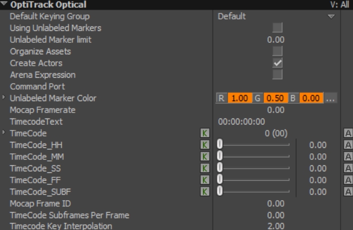
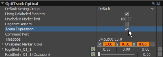
Timecode for each captured frame can also be streamed into MotionBuilder using the plugin. When the timecode data is available in Motive, you can view the streamed data under the properties of the connected OptiTrack devices.
To monitor the timecode, select the connected OptiTrack I/O devices under the Navigator taband open the Properties tab of the Resources panel as the tracking data is being streamed to MotionBuilder. Among the properties, timecode values will be reported. This will be available for any type of devices (Optical device, Skeleton device, Insight VCS device) that is connected to Motive. Please note that timecode gets streamed out only if it is available in the capture. Timecode signal can be integrated to the capture data only when SMPTE timecode signal is fed into the camera system via the eSync synchronization hub.
Timecode data is presented to MotionBuilder on each device with the following properties, which can be keyed during recording.
Use the Timecode Key Interpolation property to set the interpolation method:
0 : Constant (aka Stepping)
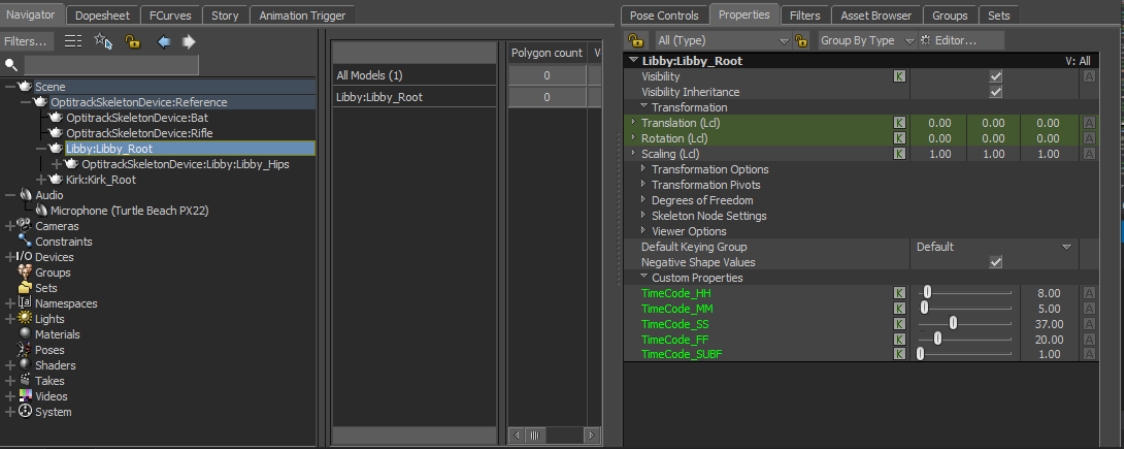
In addition to timecode on each device, the Skeleton device also writes timecode onto each skeleton asset root as an animatable user property. This allows you to export that asset only, while keeping the original timecode.
The Skeleton Device has the option of writing keys using the timecode contained in the Motive data stream. This requires:
A timecode generator
OptiTrack Ethernet Series only
OptiTrack eSync connected to timecode generator and configured in Motive for timecode.
See the for how to do this.
To enable keying to timecode, set the following Device properties:
Use Motive Timecode
Check this property to enable timestamping keys using the timecode contained in the Motive data packet.
Timecode Format
MotionBuilder defines the following formats, and the numeric value to use for the property:
NTSC_DROP : 29.97 NTSC_FULL: -29.97f PAL_25: -25.0f FILM_24 : -24.0f FILM_23976: -23.976f FRAMES_30: -30.0f FRAMES_5994: -59.94f
The OptiTrack MotionBuilder Plugin is a collection of MotionBuilder devices, scripts, and samples used for working with OptiTrack Motive data inside MotionBuilder. The device plugins allow users to stream Motive Live or from recorded .tak data into MotionBuilder.
This page is designed to help you get started with the general download and setup process, and organize the three MotionBuilder plugin pages for quick reference.
For basic instructions on setting up a motion capture system, please refer to the Getting Started guide.
Included Plugins:
OptiTrack - Skeleton
OptiTrack - Optical
OptiTrack - Insight VCS
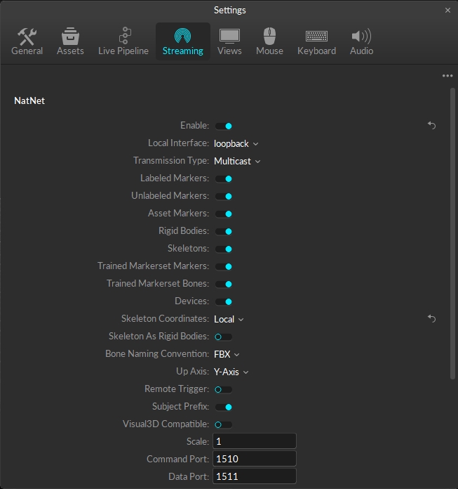
Follow the steps below to configure data streaming in Motive. When the NatNet streaming service is enabled, Motive broadcasts tracking data to a designated network interface where client applications can receive them.
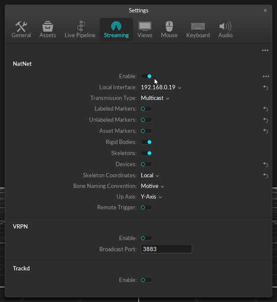
To enable streaming in Motive, click the button to open the panel, then select the tab, or use the button in the right corner of the to open the Streaming tab directly.
In the NatNet section, select Enable to begin streaming.
Select the Local Interface. Use Loopback if streaming to the same computer, otherwise select the IP address for the network where the client application resides.
Set the Bone Naming Convention to FBX if streaming skeletons.
Please see the page for more details on all settings available for streaming.
For best results, run Motive and MotionBuilder on separate computers so they are not competing for processing resources.
When streaming the data over a Wi-Fi network, use Unicast transmission.
To stream recorded data, load the Take in Motive.
Set the to Endpoint.
Begin recording in MotionBuilder.
At the desired frame, start playback in Motive. This will stream the captured Take into MotionBuilder.
If playback mode is set to Loop in Motive, MotionBuilder will stop recording once the final frame is reached even though playback continues in Motive.
For additional information on data streaming in general, read through the page.
The OptiTrack Skeleton Device allows to you map Motive 6DOF Skeleton joint angle data directly onto a MotionBuilder character
The OptiTrack Optical Plugin device allows to you to map motion capture (optical) data onto an animated character within MotionBuilder.
The Virtual Camera device is specifically designed for creating a Virtual Camera in MotionBuilder. You can use the Insight VCS device with standard OptiTrack applications such as Motive, or you can use the device in "Universal" mode, which works with generic MotionBuilder Optical or RigidBody objects, allowing you to use the Insight VCS device with alternative motion capture systems that support optical or Rigid Body devices in MotionBuilder.
After downloading the from the OptiTrack website, follow the steps below for a successful install.
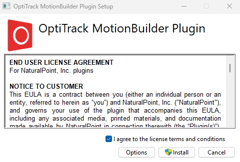
Double click the OptiTrack MotionBuilder Plugin .exe file to open the installer.
Read the End User License Agreement, then check the box "I agree to the license terms and conditions."
Click the Install button to begin the installation.
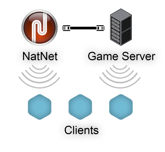
When setting up multiplayer games on wireless clients, it's best for each client to directly connect to both the tracking server (Motive) and the game server, rather than rebroadcasting the streamed tracking data through the game-server. This ensures that game-related actions that interact with the tracking data can be processed on the game server, which then sends out the corresponding updates to the wireless clients. This allows the wireless clients to receive both the tracking data or updates without having to send back any information, minimizing the number of data transfers needed. If wireless clients are sending data, it will require at least two transfers on the wireless network, with each wireless transfer increasing the risk of latency or lost packets.
2 : Cubic (MoBu default)
This must be correctly specified, and requires you to specify the format of the timecode generator that is connected to Motive via the OptiTrack eSync device.
Stop and save the recording in MotionBuilder when the Take ends in Motive.
This page provides instructions on how to use the OptiTrack MotionBuilder Skeleton plugin. This plugin allows you to map Motive 6DOF Skeleton joint angle data directly onto a MotionBuilder character.
Before following the walkthrough below, please refer to Autodesk MotionBuilder Plugin page for initial steps for setting up motive and downloading the OptiTrack MotionBuilder plugin.
First, you'll want to follow the instructions below to set up the data streaming settings in Motive. Once this is configured, Motive will be broadcasting tracking data onto a designated network interface where client applications can receive them.
Open the in Motive's Settings window and set the following settings:
Enable - Turn on the Enable setting at the top of the NatNet section.
Local Interface - Choose the desired IP network address from this dropdown to stream data over.
Loopback
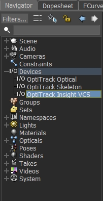
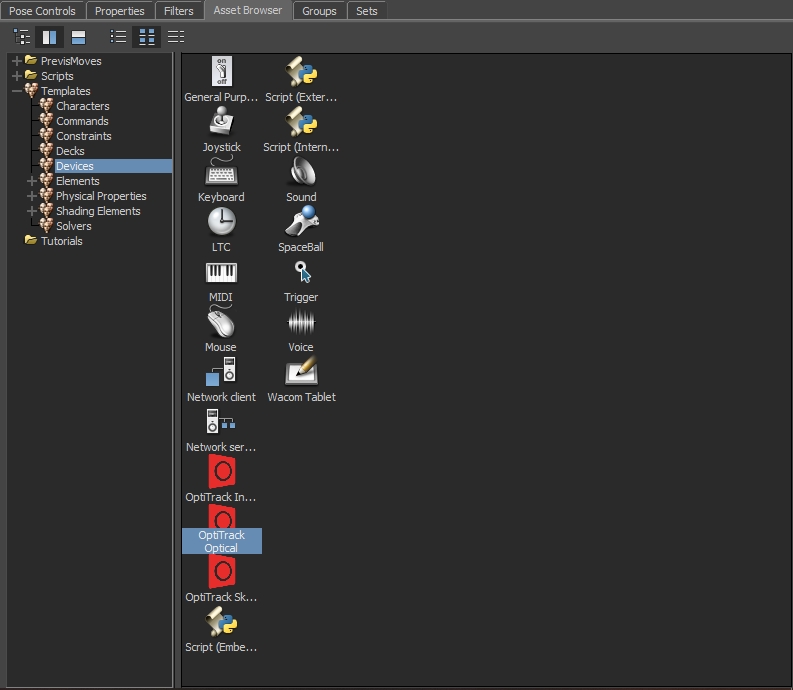
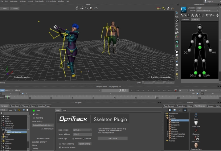
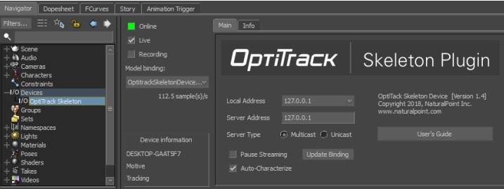
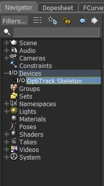
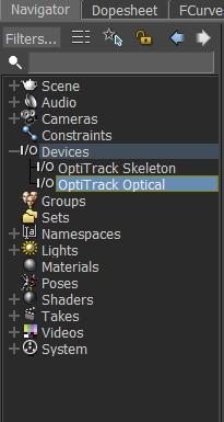
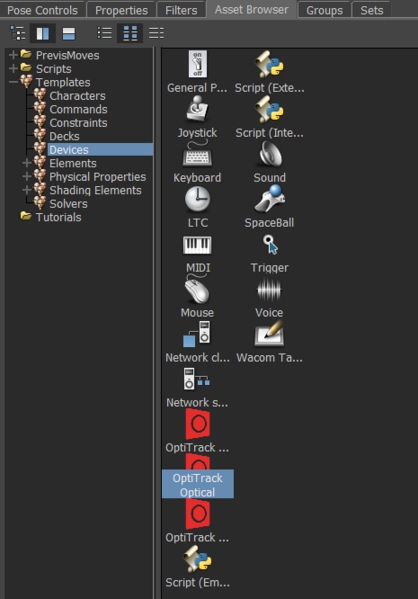
To get started, drag the OptiTrack Skeleton plugin from the Motion Builder Asset Browser tab > Devices into the Viewer window. This will create a dropdown menu called I/O Devices in the Navigator tab. Click the + button next to I/O Devices and select OptiTrack Skeleton. This will populate the plugin's settings tab if it hasn't already auto-populated from the drag and drop step from earlier.
Local address - IP address of the MotionBuilder computer. In situations where multiple network adapter cards are present, select the adapter that is on the same network as the Motive application.
127.0.0.1
This is the local computer IP address (127.0.0.1 or Localhost).
Once the above settings are input appropriately, you'll want to click the box next to Online. This indicate whether or not Motive is successfully streaming to MotionBuilder.
Online color indicator
Green - Connected and streaming.
Yellow - Connected but not streaming.
The Skeleton Device plugin uses model binding to map Motive Skeleton data to MotionBuilder animation nodes. There can be multiple model binding templates in a MotionBuilder scene. The active model binding is indicated in the model binding combo box on the Device tab.
The MotionBuilder plugin monitors the tracking model list it is receiving from the server (e.g. Motive). If it detects a change in the tracking model list, it will automatically update the current MotionBuilder Skeleton list to match, creating new Skeletons when necessary, or re-connecting to existing Skeletons where possible, based upon the Skeleton/tracking model name. It will not remove existing MotionBuilder Skeletons.
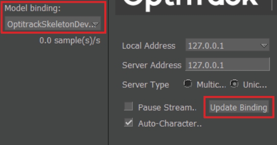
If the plugin is unable to automatically update the model template, you must update your model binding in the Skeleton Device plugin to a model binding that matches the tracked model. To do this:
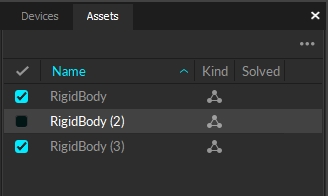
[Motive] Change the actively tracked models list by checking/unchecking the desired asset in the Asset pane.
[MotionBuilder Plugin] Press the Update Bindings button on the Skeleton Device tab.
[MotionBuilder Plugin] Select a valid model binding in the Model Binding dropdown.
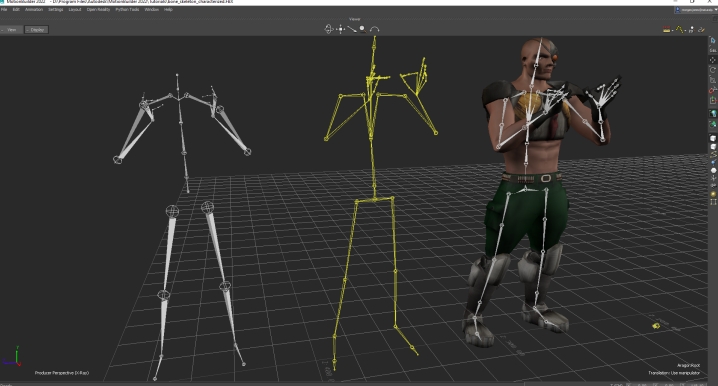
The Auto-Characterize button on the Skeleton Device will automatically characterize each generated Skeleton based on the scaled neutral pose of the performer. It will create a new MotionBuilder character with the same name as the mocap performer/MotionBuilder Skeleton pairing. The advantages of using this approach are:
Does not require Performers to be in T-Pose.
Simplifies the number of steps required to map mocap Skeleton onto your rigged MotionBuilder character.
Can result in improved retargeting results, if performs typically do not present a good T-Pose, since the characterization is on a scale neutral, or ‘zeroed’ pose.
Motive Skeleton Streaming Step-by-step
The OptiTrack Skeleton device can record optical data to the current MotionBuilder take. Please refer to the page for steps on how to record from devices into MotionBuilder.
The OptiTrack Skeleton device can be used show live data or blend live data with a recorded take. Please refer to for steps on how to record from devices into MotionBuilder.
One approach to quickly stream Motive Skeletons onto MotionBuilder characters:
[Motive] - Setup a streaming session as outlined above under . Set Data Streaming > Bone Naming Convention > FBX. If this is not set to FBX, the plugin will change this automatically when connected to the server.
[MoBu] - Connect to Motive and create a model binding as described in .
[MoBu] - Make sure the Auto-Characterize feature is enabled under the OptiTrack Skeleton Device.
This is the local computer IP address (127.0.0.1 or Localhost).
Used for streaming data locally on the PC you are running Motive on that does not interact with the LAN.
Good option for testing network issues.
192.168.0.1x (typical, but may be different depending on which interface is used to establish a LAN connection)
This IP address is the interface of the LAN either by Wi-Fi or Ethernet.
This will be the same address the Client application will use to connect to Motive.
Transmission Type
For streaming over a Wi-Fi network, setting the Transmission Type to Unicast is strongly advised.
Select desired data types to stream under streaming options:
Rigid Bodies - Enabled (required).
Skeletons - Optional for Skeleton tracking.
Markers (Labeled, Unlabled, Asset) - Disabled for HMDs (advised).
Devices - Disabled.
Skeleton Coordinates
Set to Global.
Bone Naming Convention
When streaming Skeletons, set to FBX.
In order to stream data from the Edit mode, a capture-recording must be playing back in Motive.
For additional information on data streaming in general, read through the Data Streaming page.
Use this loopback address if Motive is running on the same machine as MotionBuilder.
192.168.0.1x (typical, but may be different depending on which interface is used to establish a LAN connection)
This IP address is the interface of the LAN either by Wi-Fi or Ethernet.
Use this if Motive is running on a different computer, but on the same network as the MotionBuilder computer.
169.xxx.x.xx
This address is assigned when a DHCP server could not be reached.
This address can be ignored for our application.
Server Address - IP address of computer that is running Motive
127.0.0.1
Use this IP when both Motive and MotionBuilder are running on the same computer.
Server Type
Multicast (default) or Unicast
Must match what is selected in the Motive Streaming settings.
Multicast is default and recommended.
Pause Streaming
Pauses the live stream.
Useful when characterizing from a Live T-Pose
Update Bindings
Use to update model bindings when the actively tracked models list in Motive changes.
Only necessary if the plugin has not automatically detected the tracking list change (e.g. if the tracking list change and data was not streaming).
Auto-Characterize
Automatically characterize each generated Skeleton based on the scaled neutral pose of the performer.
It will create a new MotionBuilder character with the same name as the mocap performer/MotionBuilder Skeleton pairing.
Live
Indicates to MotionBuilder that data is coming from a live source (checked) or from a recorded take.
Recording
Indicates to MotionBuilder that data from this device should be recorded when MotionBuilder is recording.
[MoBu] - Import a rigged model. Be sure rigged model is in T-Pose facing +Z.
[MoBu] - Characterize rigged model.
[MoBu] - Rigged Model Character > Input Type > Character
[MoBu] - Rigged Model Character > Input Source > Select a Motive Character from Step 2.
[MoBu] - Rigged Model Character > Check Active. Model should snap to Motive Skeleton position.
Begin streaming/playback from Motive. Rigged model should now animate with Motive Skeleton.
[Motive]
Configure Motive for Streaming Data
From the Motive Streaming Pane:
Select Enable
Select Bone Naming Convention to FBX. (The plugin device will automatically reconfigure this if not already set to FBX.)
Choose Local Interface IP address from dropdown. If same computer is running both OptiTrack and MotionBuilder use the Loopback option.
Be sure to configure any Firewall software first (either disable or permit MotionBuilder as an exception).
[MoBu]
Create an OptiTrack Skeleton device
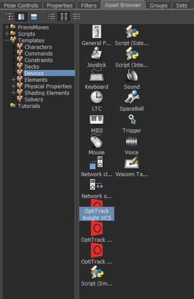
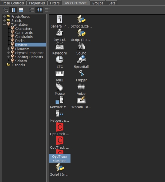
In the MotionBuilder Asset Browser Window -> Devices window. You should see:
OptiTrack Skeleton
Within MotionBuilder, drag the OptiTrack Skeleton device into the Navigator(or Viewer) pane. An instance will be created under the Devices node.
[MoBu]
Connect Skeleton Device to Motive
In the Navigator window, select OptiTrack Skeleton from the Devices node
On the OptiTrack Skeleton pane, set the IP address of the OptiTrack server (e.g. Motive).
Click on the 'Online' checkbox - it should change from red to yellow (or green if data from the OptiTrack Server is currently streaming).
[MoBu]
Create a Motive to MoBu Skeleton binding
Click the Live checkbox
Click the Model Binding Combo and select Create New
In the Navigator window, under the Scene node, you should see a new the Skeleton nodes that match the currently tracked Motive Skeletons.
[MoBu]
Begin streaming marker data
From Motive, start live capture or data playback
From MotionBuilder, ensure the Viewer window is active (MotionBuilder will not update otherwise).
The Skeleton(s) should be animating in the MotionBuilder Viewer window.
The MotionBuilder Online check boxes should be green, indicating data is live and actively streaming.
This page provides instructions on how to use the OptiTrack MotionBuilder Optical plugin. The OptiTrack Optical Plugin device allows to you to map motion capture (optical) data onto an animated character within MotionBuilder.
First, you'll want to follow the instructions below to set up the data streaming settings in Motive. Once this is configured, Motive will be broadcasting tracking data onto a designated network interface where client applications can receive them.
Enable - Turn on the Enable setting at the top of the NatNet section.
Local Interface - Choose the desired IP network address from this dropdown to stream data over.
Loopback
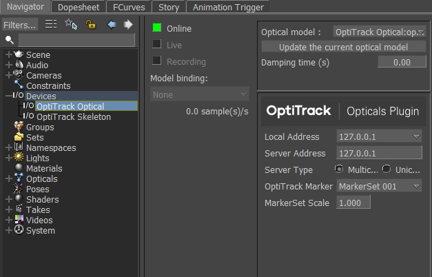
To get started, drag the OptiTrack Optical plugin from the Motion Builder Asset Browser tab > Devices into the Viewer window. This will create a dropdown menu called I/O Devices in the Navigator tab. Click the + button next to I/O Devices and select OptiTrack Optical. This will populate the plugin's settings tab if it hasn't already auto-populated from the drag and drop step from earlier.
Optical Model
Specified the MotionBuilder "Opticals" model to map the markers to.
Generate a new Optical model/Update the current optical model
Once the above settings are input appropriately, you'll want to click the box next to Online. This indicate whether or not Motive is successfully streaming to MotionBuilder.
Online color indicator
Green - Connected and streaming.
Yellow - Connected but not streaming.
Motive Skeleton Streaming Step-by-step
The OptiTrack Optical device can record streamed optical data to the current MotionBuilder take. Note that the looping feature in Motive must be disabled in order to record streamed data in MotionBuilder. The following step-by-step procedure can be used to record data:
Recording Optical Data Step-by-step
The OptiTrack Optical device can be used to show live data or blend live data with a recorded take. To playback recorded optical data, you need to tell MotionBuilder to disable live streaming.
Playing Back Recorded Data Step-by-step
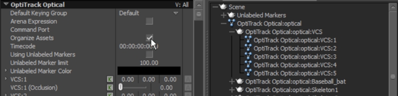
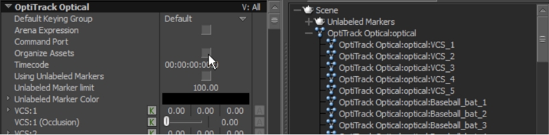
When the opticals are generated, their naming conventions will be determined depending on whether the Organize Assets option was enabled under the Optical Device properties.
Organize Assests Enabled (default)
The device will generate optical data with colon ( : ) separator (e.g. AssetName:MarkerName), and all of the optical data will be organized under their corresponding root nodes.
Organize Assets Disabled
The device will generate optical data with an underscore ( _ ) (e.g. AssetName_MarkerName) and all of the optical data will be listed under a same optical node.
The following guide is provided as a simplified process for working specifically with Motive, but this is not the only way. For the latest information on setting up and configuring MotionBuilder Actors and Characters, please refer to the .
To animate characters in MotionBuilder, you need to create the following data flow (or “mapping”):
Mocap Marker Data > MotionBuilder “Actor” > Skeleton Data > MotionBuilder “Character”
The Mocap Marker Data > MotionBuilder Actor step maps Motion Capture data (Markers) to the MotionBuilder Actor object. The MotionBuilder Actor object is a Skeleton solver that creates joint angles from Marker data.
The MotionBuilder “Actor” > Skeleton Data > MotionBuilder “Character” step is specific to MotionBuilder, and this pipeline maps the MotionBuilder Actor Skeleton onto your final character Skeleton. This step requires a “rigged” character. Refer to the MotionBuilder help for detailed information on this process.
There are 3 ways to create a Motive Marker Set > MobBu Actor mapping.
Create a new marker map from scratch.
Import a Motive exported FBX Ascii file.
Auto-create an actor from the Motive stream.
Autodesk has discontinued support for FBX Ascii import in MoBu 2018 and above.
Create OptiTrack Optical device
Connect to Motive
Generate Opticals
Stream a frame of T-Pose data from Motive
Option 1: Restore Marker Set from HIK file
[MoBu] Import Marker Set definition (.hik file)
[MoBu] Connect to Motive
[MoBu] Generate Opticals
[Motive] Stream a T-Pose frame of data into MotionBuilder
Option 2. Export FBX from Motive (Mobu 2017 and earlier only)
[Motive] Right-click on the Skeletons in the Assets pane and export Skeleton as FBX. Make sure the namespace separator is set to (_).
[MoBu] Merge FBX from Step 1 (File > Merge)
[MoBu] Connect to Motive
[MoBu] Select the OptiTrack Optical device in the navigator and access its properties under the resources panel.
The Optitrack MotionBuilder plugin can generate a MoBU Actor for you automatically.
Set the “Create Actors” property to true before bringing the Optical device online.
The Optitrack Mobu plugin will generate an Actor for each Marker Set in the Motive data stream, and correctly map the Motive Marker Set markers to the corresponding Mobu Actor.
In order to workaround Autodesk's removal of support for FBX actor import, we recommend the following:
[Motive] Load a TAK file with desired assets
[Mobu] Use Optical Device to Create Actors over stream from TAK file.
[Motive] Export TAK data from Motive (FBX or C3D)
[Mobu] Import C3D/FBX into Mobu
Do Actor Setup (Above)
Import a rigged Skeleton (File -> Merge -> Skeleton)
If Skeleton is not “characterized, characterize it:
Create MB Character (Drag onto Skeleton “hips” )
Unlabeled markers are not commonly needed in the MotionBuilder workflow, but if needed, they can get streamed through the Optical Device plugin.
[Motive] Make sure streaming of unlabeled markers is enabled in Motive’s data streaming panel.
[MoBu] Under the properties of the Optical Device loaded in the scene, make sure Using Unlabeled Markers option is enabled and the Unlabeled Marker Limit is set to the maximum number of unlabeled makers allowed in the scene.
[MoBu] In Optical Devices, generate or update the optical model.
This is the local computer IP address (127.0.0.1 or Localhost).
Used for streaming data locally on the PC you are running Motive on that does not interact with the LAN.
Good option for testing network issues.
192.168.0.1x (typical, but may be different depending on which interface is used to establish a LAN connection)
This IP address is the interface of the LAN either by Wi-Fi or Ethernet.
This will be the same address the Client application will use to connect to Motive.
Transmission Type
For streaming over a Wi-Fi network, setting the Transmission Type to Unicast is strongly advised.
Select desired data types to stream under streaming options:
Rigid Bodies - Enabled (required).
Skeletons - Optional for Skeleton tracking.
Markers (Labeled, Unlabled, Asset) - Disabled for HMDs (advised).
Devices - Disabled.
Skeleton Coordinates
Set to Local.
Bone Naming Convention
When streaming Skeletons, set to FBX.
In order to stream data from the Edit mode, a capture-recording must be playing back in Motive.
For additional information on data streaming in general, read through the Data Streaming page.
Adds/updates the current Marker Set from OptiTrack to list of MotionBuilder "Opticals" model.
Damping Time
Device damping time.
Local address - IP address of the MotionBuilder computer. In situations where multiple network adapter cards are present, select the adapter that is on the same network as the Motive application.
127.0.0.1
This is the local computer IP address (127.0.0.1 or Localhost).
Use this loopback address if Motive is running on the same machine as MotionBuilder.
192.168.0.1x (typical, but may be different depending on which interface is used to establish a LAN connection)
This IP address is the interface of the LAN either by Wi-Fi or Ethernet.
Use this if Motive is running on a different computer, but on the same network as the MotionBuilder computer.
169.xxx.x.xx
This address is assigned when a DHCP server could not be reached.
This address can be ignored for our application.
Server Address - IP address of computer that is running Motive
127.0.0.1
Use this IP when both Motive and MotionBuilder are running on the same computer.
Server Type
Multicast (default) or Unicast
Must match what is selected in the Motive Streaming settings.
Multicast is default and recommended.
OptiTrack Marker Set
The name of the OptiTrack Marker Set this optical is binding to.
Marker Set Scale
The global scale factor to be applied to the marker data before mapping to the actor.
Live
Indicates to MotionBuilder that data is coming from a live source (checked) or from a recorded take.
Recording
Indicates to MotionBuilder that data from this device should be recorded when MotionBuilder is recording.
Model Bindings
Unused.
Device Information
Information about the status of the connection.
You should see the Opticals in the MotionBuilder 3D viewer
Create MB Actor
Fit MB Actor to Opticals
Create an Optical > Marker Set > Actor mapping:
Import existing mapping
Actor > Marker Set > Import > OptiTrack HIK file
Drag all opticals (incl root) onto Actor’s “Reference Cell”
Create a new mapping:
Actor > Marker Set > Create
Drag individual opticals to Actor segments
Activate Actor (Actor > Activate)
Actor snaps to marker cloud pose
Actor should now be animating in Viewer
[MoBu] Actor Panel : Drag Opticals to Actor Markers (Actor Prop Sheet > Reference)
[MoBu] Activate Actor (Actor > Activate)
Actor snaps to marker cloud pose
Actor should now be animating in Viewer
[MoBu] Disable Organize Assets property to generate Opticals with underscore separators in its names.
[MoBu] Generate Opticals.
[Motive] Stream a T-Pose frame of data into MotionBuilder
[MoBu] Actor Panel : Select all of the streamed Opticals and Drag them onto the Actor Markers (Actor Prop Sheet > Reference). The names under the marker name sheet MUST match the Skeleton labels for auto-mapping.
[MoBu] Activate Actor (Actor > Activate)
Actor snaps to marker cloud pose
Actor should now be animating in Viewer
[Mobu] Update Actor binding to imported C3D / FBX
Map Character to Actor
Select Character -> Character Settings -> Input Type -> Actor Input
Check “Active”
Activate Actor (Actor -> Activate)
Skeleton and Actor should now be animating in Viewer
[Motive]
Configure Motive for Streaming Data
From the Motive Streaming Pane:
Select Enable
Select Bone Naming Convention to FBX. (The plugin device will automatically reconfigure this if not already set to FBX.)
Choose Local Interface IP address from dropdown. If same computer is running both OptiTrack and MotionBuilder use the Loopback option.
Be sure to configure any Firewall software first (either disable or permit MotionBuilder as an exception).
[MoBu]
Create an OptiTrack Optical device
In the MotionBuilder Asset Browser Window > Devices window. You should see:
OptiTrack Optical
Within MotionBuilder, drag the OptiTrack Optical device into the Navigator(or Viewer) pane. An instance will be created under the Devices node.
[MoBu]
Connect Optical Device to Motive
In the Navigator window, select OptiTrack Optical from the Devices node
On the OptiTrack Optical pane, set the IP address of the OptiTrack server (e.g. Motive).
Click on the Online box - it should change from red to yellow (or green if data from the OptiTrack Server is currently streaming).
[MoBu]
Create a Marker Set > Opticals Mapping
In the 'OptiTrack Marker Set's Dropdown, select the name of a currently defined Marker Set in Motive. You may need to resize the device pane in MotionBuilder to access the features.
Press the Generate new optical model button
In the Navigator window, under the Opticals node, you should see a new the marker list. This indicates the plugin has successfully retrieved the marker list from the OptiTrack server. You should also see the Opticals displayed in the Viewer window if the Server is currently streaming.
[MoBu]
Begin streaming marker data
From Motive, start live capture or data playback
From MotionBuilder, ensure the Viewer window is active (MotionBuilder will not update otherwise).
The marker set should be animating in the MotionBuilder Viewer window.
The MotionBuilder Online check boxes should be green, indicating data is live and actively streaming.
Enable Optical Device for recording
[Mobu] > Optical > Check Recording
Start Recording
[Mobu] > Transport Control > Record (Create new take)
[Mobu] > Transport Control > Play ( start recording frames)
[Mobu] > Transport Control > Stop
Disable Live streaming
[Mobu] > Optical > Uncheck Recording
[Mobu] > Optical > Uncheck Live
Playback recorded take
[Mobu] > Transport Control > Rewind
[Mobu] > Transport Control > Play


This page provides instructions on how to use the OptiTrack MotionBuilder Virtual Camera Device (Insight VCS) plugin. The Virtual Camera device is specifically designed for creating a Virtual Camera in MotionBuilder. You can use the Insight VCS device with standard OptiTrack applications such as Motive, or you can use the device in "Universal" mode, which works with generic MotionBuilder Optical or RigidBody objects, allowing you to use the Insight VCS device with alternative motion capture systems that support optical or Rigid Body devices in MotionBuilder.
Before following the walkthrough below, please refer to Autodesk MotionBuilder Plugin page for initial steps for setting up motive and downloading the OptiTrack MotionBuilder plugin.
First, you'll want to follow the instructions below to set up the data streaming settings in Motive. Once this is configured, Motive will be broadcasting tracking data onto a designated network interface where client applications can receive them.
Enable - Turn on the Enable setting at the top of the NatNet section.
Local Interface - Choose the desired IP network address from this dropdown to stream data over.
Loopback
To get started, drag the OptiTrack Optical plugin from the Motion Builder Asset Browser tab > Devices into the Viewer window. This will create a dropdown menu called I/O Devices in the Navigator tab. Click the + button next to I/O Devices and select OptiTrack Optical. This will populate the plugin's settings tab if it hasn't already auto-populated from the drag and drop step from earlier.
Local address - IP address of the MotionBuilder computer. In situations where multiple network adapter cards are present, select the adapter that is on the same network as the Motive application.
127.0.0.1
This is the local computer IP address (127.0.0.1 or Localhost).
Once the above settings are input appropriately, you'll want to click the box next to Online. This indicate whether or not Motive is successfully streaming to MotionBuilder.
Online color indicator
Green - Connected and streaming.
Yellow - Connected but not streaming.
First you'll need to create the "neutral" or "zero" orientation of a Rigid Body
The “neutral” or “zero” orientation of a Rigid Body is the orientation when it is created in Motive. This will be the camera’s neutral orientation. In addition, for correct interpretation into MotionBuilder’s coordinate system, it is important you align your Rigid Body with the correct axis and coordinate system convention as follows:
Point your tracking controller (e.g. VCS Pro) along physical volume -Z axis.
After correctly orienting your Rigid Body follow the steps below to continue with the setup:
[Motive] Create a Rigid Body from your tracking controller’s markers.
[OptiTrack Server App] Enable network streaming (make sure Rigid Body data is streaming).
[MotionBuilder] Drag the OptiTrack Insight VCS device from the Motion Builder Asset Browser Panel into the Viewer or Navigator window.
[Insight VCS Panel] Connect to an OptiTrack Server (e.g. Motive, Arena, TrackingTools) by clicking the “Online” checkbox. If the connection was successful and data is streaming from you OptiTrack server application, this box will change from Red to Green.
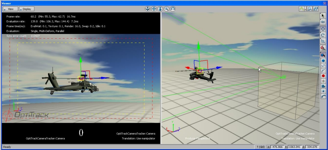
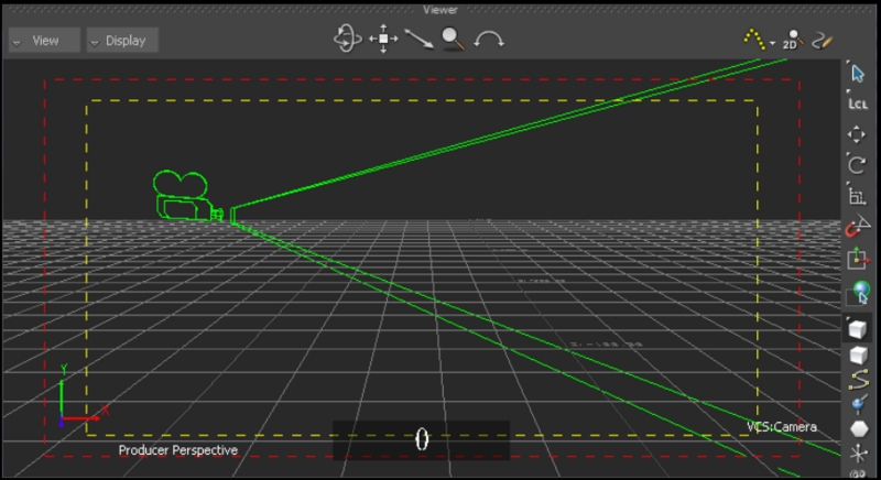
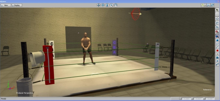
You should now see a standard MotionBuilder Camera moving within your 3D scene:
In Universal mode, a MotionBuilder Rigid Body is used to drive a camera position. This position/orientation information is merged with the VCS camera controls and applied to the camera's final state (position, lens settings, etc.). It is assumed the Rigid Body orientation matches the MotionBuilder default camera orientation (camera lens aimed down +X axis). For example, if streaming from Motive, create a Rigid Body in MotionBuilder from the optical data, with the camera lens aimed down +X in MotionBuilder.
[MotionBuilder] Create a Rigid Body or a Marker. For a Marker:
Create a bone (or some rigid element) from the geometry your 6DOF system streams into MotionBuilder
Create a MotionBuilder "Marker" element, and make this new marker a child of the bone
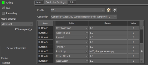
The Insight VCS plugin supports any DirectInput compatible joystick or USB device. Controllers can then be configured to perform actions or control the camera using Controller Profiles.
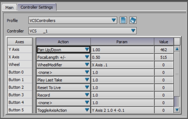
Virtual Camera controls are managed by a Control-to-Event mapping system called the Controller Profile. The controller profile is configured in the Controller Tab. The Insight VCS plugin allows you to create and swap between multiple controller profiles, allowing you to create any number of custom button/axis configurations depending upon the scene, particular move types, different physical VCS controllers or HID devices, etc. Profiles can be saved and then later swapped out using the Profile Dropdown. Profiles are saved into <VCS Mobu install folder>\Profiles folder.
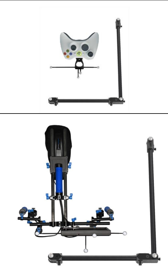
The VCS plugin ships with 2 default profiles:
The 2 controller VCS Pro (<VCS Mobu install folder>\Profiles\VCSProDefault.xml).
The XBox based VCS Mini (<VCS Mobu install folder>\Profiles\VCSMiniDefault.xml).
When the Insight VCS plugin is first launched, it will attempt to detect any compatible controllers. It will then attempt to match the detected controllers with an existing Controller Profile, beginning with the last used ("preferred") profile.
The VCS plugin supports 2 types of controller inputs and 2 types of actions:
Axis Inputs / Actions
Axis inputs are analog inputs and represent the range of values. This range has been scaled to [0, 1000]. Axis inputs can be assigned to Axis actions. PTZ operations (Pan, Tilt, Zoom) are good examples of typical Axis Actions.
Button Inputs / Actions
Button inputs are the button inputs on the controller. These are “one shot” events that occur when the button is pressed. Transport commands such as Play, Record, and Rewind are typical examples of “one shot” events.
Insight VCS Inputs/Action Settings
Some actions have parameters that modify the way they operate. The following tables list the axis and button actions, and how the parameter value for that action is interpreted.
VCS Controller - Axis Actions
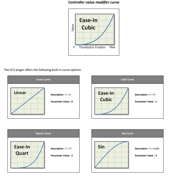
When mapping a controller thumbstick axis to an animatable camera parameter (pan, zoom), you have the option of specifying how the Insight VCS plugin should interpret controller axis movement as a standard animation curve. Instead of modifying the value over time, however, the motion curve modifies the value over the controller span, from neutral/center position (0) to maximum position (Max). The following diagram describes this relationship:
VCS Controller - Button Actions
When using the Run Script action to map button presses to MotionBuilder scripts, be sure to note the following:
Scripts must be placed in the MotionBuilder scripts folder in order to be correctly located. For a typical MotionBuilder installation this folder is:
C:\Program Files\Autodesk\MotionBuilder 2014\bin\config\Scripts:
The RunScript Param is the filename of the script, including the .py extension:
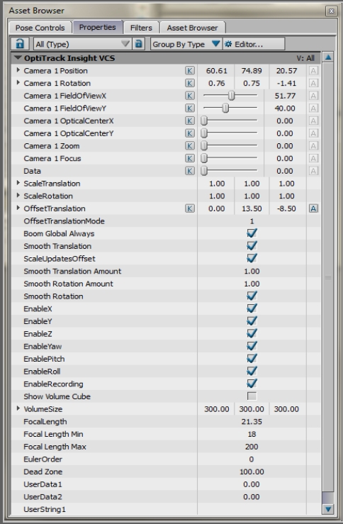
The Insight VCS plugin has several properties that can be used to customize its behavior. These properties can be accessed in the same manner as any other MotionBuilder object property, such as from the Asset Browser or from MotionBuilder's Python scripting environment.
A MotionBuilder Camera controls how you see the 3D scene. MotionBuilder’s Camera object allow users the ability to model realworld cameras, including settings such as Focal length, aspect ratio, film format, etc.
Refer to the for more information on Camera Settings.
This is the local computer IP address (127.0.0.1 or Localhost).
Used for streaming data locally on the PC you are running Motive on that does not interact with the LAN.
Good option for testing network issues.
192.168.0.1x (typical, but may be different depending on which interface is used to establish a LAN connection)
This IP address is the interface of the LAN either by Wi-Fi or Ethernet.
This will be the same address the Client application will use to connect to Motive.
Transmission Type
For streaming over a Wi-Fi network, setting the Transmission Type to Unicast is strongly advised.
Select desired data types to stream under streaming options:
Rigid Bodies - Enabled (required).
Skeletons - Optional for Skeleton tracking.
Markers (Labeled, Unlabled, Asset) - Disabled for HMDs (advised).
Devices - Disabled.
Skeleton Coordinates
Set to Local.
Bone Naming Convention
When streaming Skeletons, set to FBX.
In order to stream data from the Edit mode, a capture-recording must be playing back in Motive.
For additional information on data streaming in general, read through the Data Streaming page.
Use this loopback address if Motive is running on the same machine as MotionBuilder.
192.168.0.1x (typical, but may be different depending on which interface is used to establish a LAN connection)
This IP address is the interface of the LAN either by Wi-Fi or Ethernet.
Use this if Motive is running on a different computer, but on the same network as the MotionBuilder computer.
169.xxx.x.xx
This address is assigned when a DHCP server could not be reached.
This address can be ignored for our application.
Server Address - IP address of computer that is running Motive
127.0.0.1
Use this IP when both Motive and MotionBuilder are running on the same computer.
Server Type
Multicast (default) or Unicast
Must match what is selected in the Motive Streaming settings.
Multicast is default and recommended.
Live
Indicates to MotionBuilder that data is coming from a live source (checked) or from a recorded take.
Recording
Indicates to MotionBuilder that data from this device should be recorded when MotionBuilder is recording.
Model Binding
Indicates the MotionBuilder Camera to be controlled by the tracking controller.
Device Information
Information about the status of the connection.
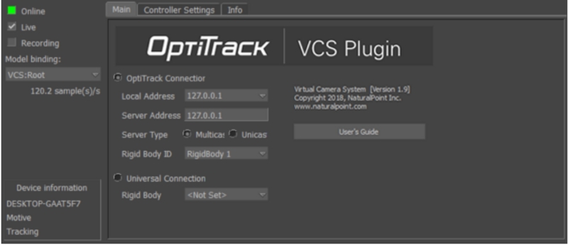
OptiTrack Connection
Indicates the data source is an OptiTrack server application.
Universal Connection
Indicates the data source is a generic MotionBuilder RigidBody.
Rigid Body ID
[OptiTrack Connection] Name of the OptiTrack server application’s Rigid Body to use for tracking.
Rigid Body
[Universal Connection] Name of the MotionBuilder RigidBody to use as a position/orientation source.
Control common actions like recording and playback using the controller.
Custom Commands
Customize the controller by mapping controller inputs to execute scripts for complete control and one-person camera operation.
[Insight VCS Panel] Create a new MotionBuilder camera using the Model Binding dropdown.
[Insight VCS Panel] [Optional] If tracking more than one Rigid Body object in your OptiTrack server application, select the Rigid Body you wish to use as your tracking source using the Rigid Body ID dropdown on the CameraTracker device panel (Note: the camera tracker will automatically default to the first detected Rigid Body).
. Use this “Marker” in the VCS universal dropdown to drive the 6DOF data of the VCS.
[Insight VCS Panel] Check the "Universal Connection" Radio.
[Insight VCS Panel] Check "Online".
[Insight VCS Panel] Create a new MotionBuilder camera binding using the Model Binding dropdown.
[Insight VCS Panel] Select the Rigid Body you created in step 1 using the Rigid Body dropdown in the Universal Connection group box.
Offset Rotation
[Focal length change rate] [Curve Type]
1.0
Orbit Offset
[Orbit offset change rate] [Curve Type]
1.0
Focal Distance
[Focal distance change rate] [Curve Type]
1.0
Wheel Modifier
[VCS Dial controls only] Modify an axis' parameter value (e.g. zoom speed, pan speed, translation scale) by a specified increment.Format:
[axis name] [increment]
Examples:
X Axis .1 (+/- the X Axis parameter by 0.1)
Y Axis .2 (+/- the Y Axis parameter by 0.2)
Z Axis .1 (+/- the Z Axis parameter by 0.1)
Rotate Right/Left
[Rotate Speed] [Curve Type]
1.0 [ rotate at normal rate, linear curve]
1.0 1 [rotate at normal rate, ease-in curve]
0.5 1 [rotate at half speed, ease-in curve]
2.0 [rotate at 2x speed ]
Rotate Up/Down
[Rotate Speed] [Curve Type]
SAME AS ABOVE
Tilt Right/Left
[Rotate Speed] [Curve Type]
SAME AS ABOVE
Runs a MotionBuilder python script. This script must be located in your MotionBuilder scripts root folder.
ResetOffset.py
ToggleAxisAction
Toggles a specified axis between 2 actions.
[Axis name],[Action1 Index], [Action1 Params],[Action2 Index],[Action2 Params]
The example at right toggles the Y Axis behavior between Dolly In/Out at speed 1.0 with a Cubic Curve and Focal Length at 0.1 speed with a Quartic curve.
Y Axis, 3, 1.0 1, 4, 0.1 2
Pause
None.
Stop
None.
Rewind
None.
Suspend Tracking
None.
Scale Translation +/-
Increment amount.
.5
Scale Rotation +/-
Increment amount.
.5
Zoom +/-
Increment amount.
.5
FOV +/-
Increment amount.
.5
Playback Speed +/-
Enumerated value that matches MoBu transport.
2
Reset Zoom
Focal Length to reset to.
50.0
Reset Offset
[x y z] Optional - specifies the position to reset camera to, otherwise camera is reset to (0.0,0.0,0.0).
10.0 10.0 0.0 [reset camera offset to 10,10,0]
Reset Rotation Offset
[x y z] Optional - specifies the rotation vector to reset to (in degrees), otherwise camera is reset to (0.0,0.0,0.0).
0.0 90.0 0.0 ( reset camera to 90 degrees yaw)
Reset Orbit Offset
None.
Change Camera
None.
Play Last Take
None.
Reset to Live
None.
Instructs whether changes to Scale Translation update the Offset Translation value in order to keep the camera in the same position (true) or does not affect Offset Translation, resulting in camera position moving to new scaled amount.
Smooth Translation Amount
Applies smoothing to the camera position values.
Smooth Rotation Amount
Applies smoothing to the camera rotation values.
Dead Zone
Controller thumbsticks do not typically restore to an exact center value. Dead Zone can be used to specify a value range around thumbstick center that should be ignored. This can be used, for example, to prevent drift in pan/dolly/zoom when thumbsticks are mapped to these actions.
Pan/Dolly/Boom
Use VCS controls to Pan Left/Right and Up/Down. Pan in local, world, or a combination of coordinate systems. Adjust pan speeds on the fly with controls or scripts.
Pitch/Tilt/Roll
Absolute orientation at all times from the OptiTrack optical system.
Free Move
Absolute position at all times from the OptiTrack optical system. Scale movement in real-time with controllers or from script.
Zoom
Fully control camera zoom/FOV and zoom rates using the controller's analog thumbsticks and speed adjusters.
Smooth
Advanced Kalman filtering allows for customizing a "Steadicam" feeling.
Axes
Name of the controller’s analog input.
Action
Action to take or value to change.
Param
Input parameter used by some actions to modify the action in some way (e.g. speed up or slowdown zooming).
Value
Current value of the control input.
Pan Right/Left
[Pan Speed] [Curve Type]
1.0 [ pan at normal rate, linear curve]
1.0 1 [ pan at normal rate, ease-in curve]
0.5 1 [ pan at half speed, ease-in curve]
2.0 [ pan at 2x speed ]
Dolly In/Out
[Pan Speed] [Curve Type]
1.0
Pan Up/Down
[Pan Speed] [Curve Type]
1.0
Record
Copy data from previous take.
true
Play
None.
Fullscreen
Toggles between Fullscreen and the MotionBuilder GUI. On return to the MotionBuilder GUI, this parameter indicates the number of viewports to show.
2
Scale Translation
Scale the physical movement (when tracking controller is moved).
Scale Rotation
Scale the physical movement (when tracking controller is moved).
Offset Translation
Can be used for 2 purposes :
To adjust the center of the physical volume to the virtual scene.
To effectively pan/truck/dolly the camera. This value is updated by the thumbstick controls for the Pan/dolly/truck operations
OffsetTranslationMode
Affects how Offset Translation is applied to the camera:
0 : Global Translates the camera according to the MotionBuilder global coordinate system (global)
1 : Local Translates the camera according to the camera’s coordinate system (local).
2 : LocalOnStart Translates the camera according to the camera’s coordinate system when the camera first moves (stick first moves), then keeps that axis (Does not continuously update the coordinate system).
Boom Global Always
Always pan camera up/down in the global Y axis, regardless of the OffsetTranslationMode
Play/Record
Focal Length +/-
RunScript
Scale Updates Offset
Translate All 1.0 (+/- all pan speeds by 1.0)