Loading...
Loading...
Loading...
Loading...
Loading...
Loading...
Loading...
Loading...
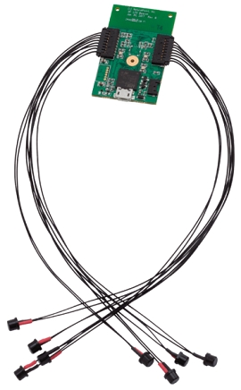
An overview of Active Tags, including power requirements, the type of Pin Out connectors used, and additional details on the IR LEDs.
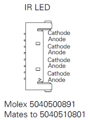
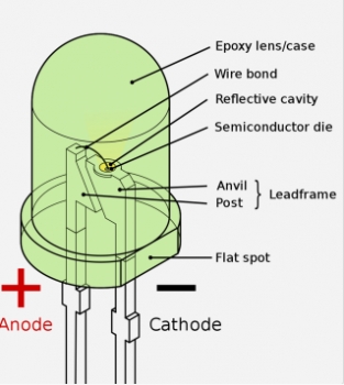
The assembly of the Active Tags and the LEDs are relatively straightforward; connect the wires to the correct cathode/anode terminals using the diagrams, below.
Battery: Only use batteries that were supplied by OptiTrack.
3.3 - 5.0V inputs for micro and alternate USB connectors.
Recommended to use the LEDs that are provided directly from us.
Other LEDs must work within the following specifications: 1.5 < VLED < 2.5 and ILEDMAX = 100mA
The wires to the LEDs are 30AWG 7 gauge strands.
The following connectors from Molex are used on the Tags to connect the IR LEDs. Please search the corresponding part number on their for specific information.
The longer leg on the LED is the cathode of this LED. As shown in the image below, The flat spot can also be referenced to indicate the cathode of this LED. Always remember this flat spot for these black LEDs, and connect the black wire (negative) when using red/black wire pairs.
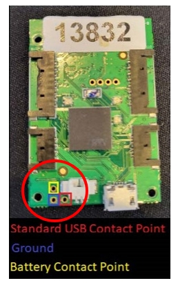
The Active tag has three contact points in the bottom left corner that can be used as an alternative connection point for a power source (Battery or USB).
There is risk for short circuit when using these contact points to power the Active Tag. Please proceed with caution if using contact points to power Active Tags.
There are two methods to power the tag using contact points:
CAUTION!
Do not connect a USB cable to the board while using these pinouts. Doing so poses a risk of short-circuiting and causing damage to the board.
Connect the contact point at the top (highlighted in yellow in the image, above) to the positive terminal of a one-cell, Li-Ion 3.7v battery.
Connect the bottom left contact point (the ground, highlighted in blue, above) to the negative terminal of the battery.
Do not permanently solder the battery to the contact points as the battery cannot be charged (in any manner) while connected to the Active Tag.
Connect the bottom right contact point (highlighted in red, above) to a standard 5V USB source for power.
Connect the USB ground connection to the ground contact point (highlighted in blue, above).
CAUTION!
Do not connect a USB cable to the board while using these pinouts. Doing so poses a risk of short-circuiting and causing damage to the board.
Quick Start Guide, specifications, and additional information for the Wired AnchorPuck.
The Wired AnchorPuck is OptiTrack’s purpose-built tracking tool for Virtual Production, Studios, and Stages.
Powered and connected to the camera system through a PoE+ switch, the Wired AnchorPuck is able to use higher-powered LEDs than a battery-operated Puck. Without a battery to charge, the Wired AnchorPuck is truly a set-it-and-forget-it device.
With up to 12 extended markers that can be attached and placed at specific, non-changing points of reference in the volume, the Wired AnchorPuck is the perfect tool for in your capture volume.
The Wired AnchorPuck’s settings can be changed directly within the Motive software, without the need for the Active Batch Programmer. This allows you to quickly reconfigure the Wired AnchorPuck in place whenever needed.
The Wired AnchorPuck has five mounting options, to accommodate different environments and mounting surfaces.
The Flat Strap mount has 2 hook and loop straps that wrap around a flat surface to which the Wired AnchorPuck is being mounted.
Insert the Wired AnchorPuck into the mounting panel and secure it using the 4 locking knobs.
Wrap the straps around the surface, pulling each strap through its loop until secured.
The Pipe Strap mount has 2 hook and loop straps that wrap around a round surface up to 3" in diameter, such as a pipe or speed rail.
Attach the LED cables to the ports on either side of the Wired AnchorPuck. At least 1 LED cable is required, up to 12 can be attached.
LED cables come in various lengths that can be extended with the optional Extension Cables as needed.
Connect the Wired AnchorPuck to a PoE+ switch on the camera system network using a shielded Cat 6 or Cat 6a Ethernet cable.
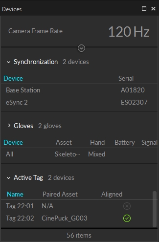
When connected to the OptiTrack system, the Wired AnchorPuck IMU is shown in the . Select it to view its properties in the Properties pane.
The following specifications apply for active IR LEDs on the Wired AnchorPuck:
850 nm IR spectrum
12 LEDs
LED Output High
Illuminations synchronized with camera exposures
Detailed instructions on integrating Manus gloves with an OptiTrack motion capture system.
Starting from Motive 3.0 and above, these gloves can be integrated into Motive. This allows for easy integration of the external glove tracking system directly in Motive so that it can be used in tandem with the OptiTrack system to provide a more comprehensive tracking solution.
Required Components
Manus Glove Prime X and Manus Glove Dongle.
Manus Core and Dashboard software
Motive 3.0 or above
(optional) MoCap suit and markers for full body capture.
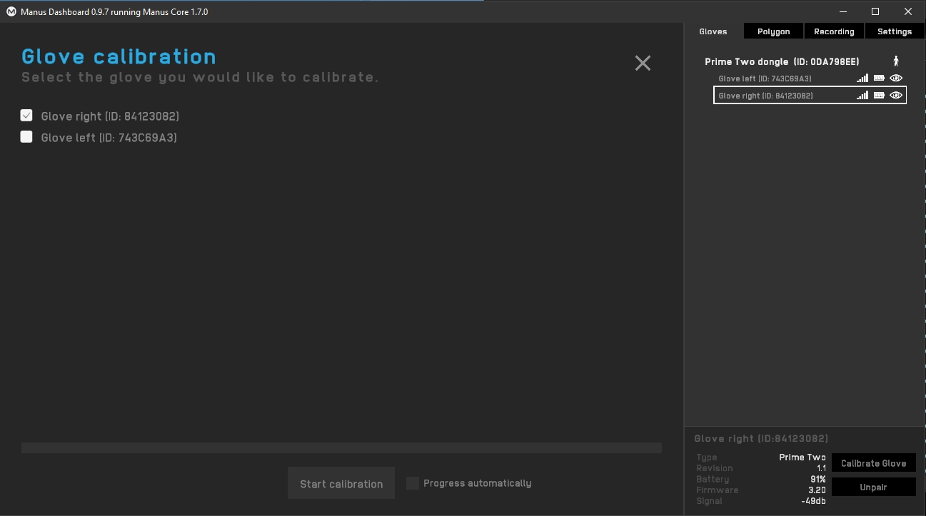
Before using Manus VR gloves in Motive, please ensure all gloves have been paired, calibrated and are able to report data from Manus software. This is a crucial first step for the successful use of Manus Gloves with Motive software.
Start the Manus Dashboard software.
Insert the Manus Glove Dongle(s) onto the computer. Do not connect the dongle into the same USB bus used by the USB Security or Hardware Key as this can cause conflicts with device detection.
Power on the Manus Gloves.
(optional) You may need to pair the glove with the dongle if needed. The gloves should come already paired.
Before starting Motive, please make sure to launch Manus Dashboard and Manus Core software first.
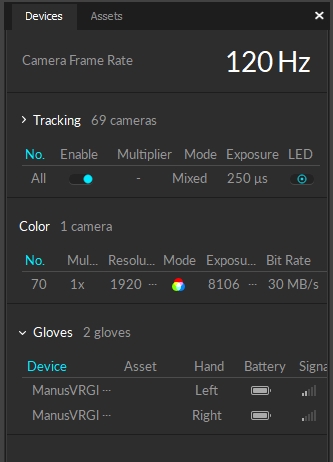
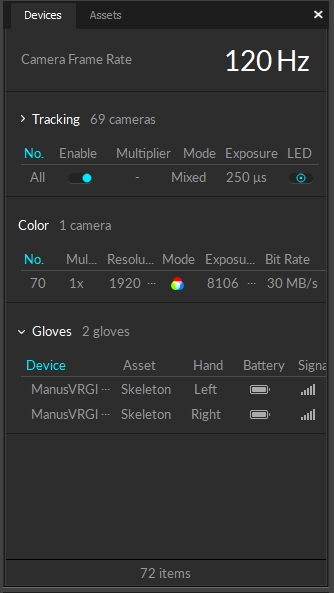
Launch Motive. If the Manus VR is properly set up on the computer, connected gloves will be listed under the .
Use the Builder pane to define a in Motive. You can use any Skeleton model that is not designed to track fingers using motion capture data. The recommended Skeletons models to use are the Core 50 or Baseline 41.
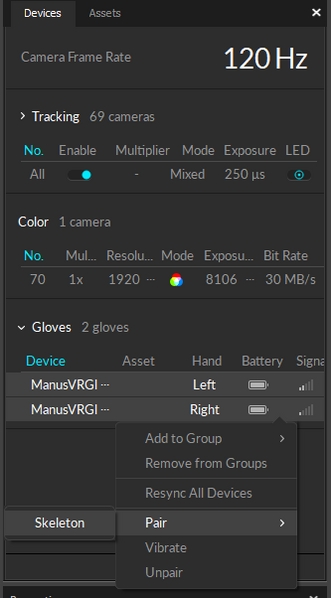
After a Skeleton has been defined, pair the Skeleton to the glove device. Open the , right-click on the listed glove device, and pair it to the Skeleton as shown in the screenshot below.
Once the glove has been configured and paired with the created Skeleton, the fingers will be tracking in Motive.
Once Motive starts tracking the glove, the finger tracking data can be outputted for various applications. Real-time finger data can be streamed into any NatNet client, and recorded finger data can be exported into other file formats. For instructions on outputting tracking data from Motive, refer to the following pages:
Quick Start Guide, specifications, and additional information about the Wired CinePuck.
The Wired CinePuck is OptiTrack’s purpose-built tracking tool for Virtual Production and Broadcast studios. An Ethernet-connected device, the Wired CinePuck allows extended detection ranges and increased positional precision while eliminating dropped frames caused by external RF noise. Additionally, OptiTrack’s Motive software allows you to fuse the Wired CinePuck’s IMU data with its optical data to provide the highest quality object tracking possible.
For more information on how to use CinePucks for Virtual Production, please see our for detailed instructions.
Insert the Wired AnchorPuck into the mounting panel and secure it using the 4 locking knobs.
Position the mount with the pipe grip against the pipe.
Wrap the straps around the pipe, pulling each strap through its loop until secured.
The 1/4 -20 mount attaches the Wired AnchorPuck to a 1/4-20 standard tripod mount.
Insert the Wired AnchorPuck into the mounting panel and secure it using the 4 locking knobs.
Attach the mount to the tripod.
The Bolt mount attaches the Wired AnchorPuck to a surface using up to 5 M5 bolts.
Insert the Wired AnchorPuck into the mounting panel and secure it using the 4 locking knobs.
Attach the mount to the surface using M5 bolts.
The Bolt mount attaches the Wired AnchorPuck to a surfacing using an anodized aluminum ARRI interface.
Insert the Wired AnchorPuck into the mounting panel and secure it using the 4 locking knobs.
Attach the mount to the tripod using a single ARRI connector.
Bolt Mount
ARRI Mount
Please see the section Mount the Wired AnchorPuck, above, for more information, including technical diagrams for each mount.
Use only fully-shielded Cat 6 or Cat 6a cables. Please see the Ethernet Cabling Requirements section of the Cabling and Load Balancing page for more information on Ethernet cables and network configuration.


Sync: Manus gloves do not support hardware synchronization. Thus, Motive uses a software synchronization scheme to attempt to keep Manus glove 'as close as possible' to mocap data.
Manus Dongle: Plug the Manus dongle on a separate USB bus from the one used to connect the USB Security or Hardware Key. If both dongles are connected into the same bus, it may cause conflicts with Motive activation.
Calibrate each glove. This involves going through a series of hand gestures to calibrate the glove to the user’s hand. This helps give more robust finger solve data.
Start Motive and the gloves should appear in the Devices pane.
For information on the CinePuck, please visit the CinePuck page.
Attach the Wired CinePuck to the movie camera using either:
1/4"-20 threads 6X for standard tripod mounts
3/8"-16 threads 1X for optional ARRI-style anti-twist mount
Connect the Wired CinePuck to a PoE or PoE+ switch on the camera system network using a shielded Cat 6 or Cat 6a Ethernet cable.
Once connected, the Wired CinePuck will receive power from the switch.
When connected to the OptiTrack system, the Wired CinePuck IMU is shown in the Devices Pane. Select it to view its properties in the Properties pane.
To use a Wired CinePuck in Motive, it must first be an asset. Please see the Builder pane page for instructions on creating a rigid body asset, and the IMU Sensor Fusion page for detailed instructions on pairing the IMU.
Once the Wired CinePuck rigid body is created, it will be available in the Assets pane, where you can also select it to view the IMU-related properties in the Sensor Fusion section of the Properties pane.
Diffuser Posts are optional accessories that improve the trackability of the Wired CinePuck in situations where the built-in flat markers may become occluded.
The Diffuser Post kit includes 1" and 2" posts, eleven of each, along with a spudger tool for removing the flat markers.
The Wired CinePuck has a small slot next to each flat marker, as shown in the image, below.
Gently insert the corner of the spudger into the slot of the flat marker you wish to remove and pry the marker from the Wired CinePuck casing.
Once the flat marker is removed, place the marker post you wish to attach over the LED until you feel the magnet snap it into place.
The following specifications apply for active IR LEDs on the Wired CinePuck:
850 nm IR spectrum
11 LEDs
LED Output Standard
Illuminations synchronized with camera exposures
Optical Detection Distance:
Top Diffusers (only): 24m
All Diffusers: 18m
The following specifications apply for active IR LEDs on both the Tags and the Pucks.
850 nm IR spectrum.
8 LEDs with removable diffusers (9.5mm, 3/8", diameter) on four corner LED locations
Illuminations synchronized with camera exposures
Illumination angle:
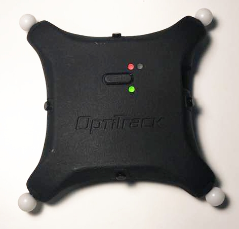
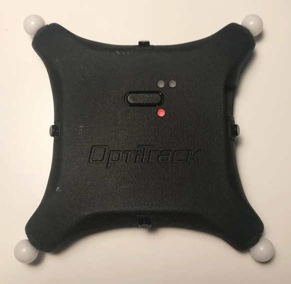
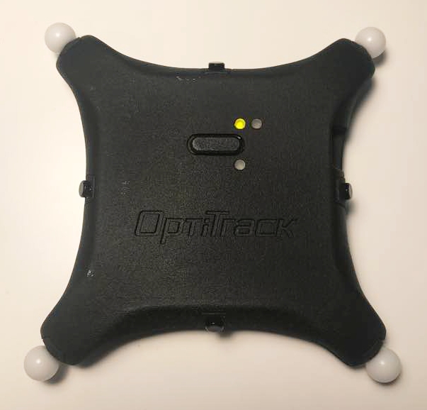
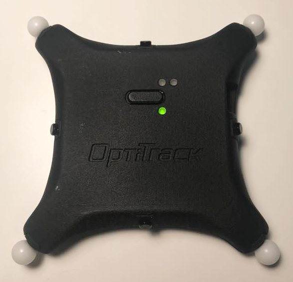
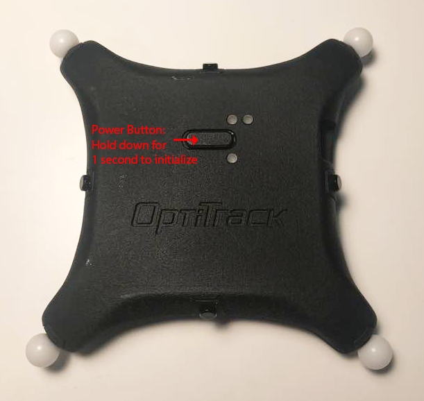
Power on: Press down on the button for ~1 second to turn on the puck. It will illuminate the top LED in orange for a few seconds until it initializes.
Power off: Hold down the button for ~2 seconds
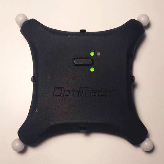
Battery status check: Press down on the button while the puck is powered on to illuminate the battery status LED.
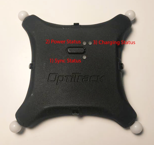
Three plainly visible status LEDs for indication of battery status, sync status, and charging status.
The bottom LED indicates the sync status. When the puck is successfully synchronized with a base station, it will start receiving sync packets, and this bottom LED will start blinking green roughly at 10 Hz rate:
Blinking green: Sync packets are being received.
Red: The first sync packet has not been received yet. At this stage, the puck is waiting for the packet.
Continuous green: The first packet was received for initial synchronization but sync packet is no longer being received.
Normal: illuminates in green and blinks every 5 seconds. You can also press on the power button to check the battery.
Color indicator:
Green (Good charge) - battery sufficient
Red: Charging / Idle
Green: Fully Charged
Yellow/orange: Bad battery. Stop using the puck and contact support.
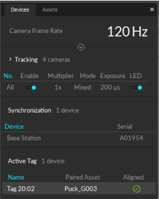
When connected to the OptiTrack system, the properties for the Active puck and its associated Base Station are shown in the Devices Pane. Please see the page for more details.
Please see the page for instructions on creating a , and the page for instruction on pairing the active tag to an asset.
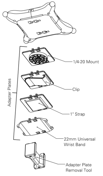
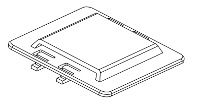
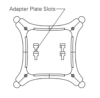
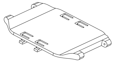
Each Active Puck has four slots on the back where an accessory adaptor plate can be fitted into. These adapter plates can be purchased from our , and they provide the Active Puck various mounting options for attaching onto different types of objects.
There are four different types of adapter plate accessories that can be fitted onto an Active Puck:
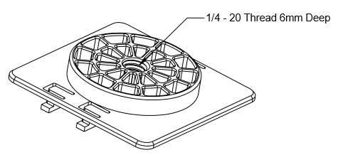
Adapter plate with a 1/4-20 mount
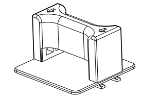
Adapter plate with a clip
Adapter plate with a 1" strap slot
Adapter plate with 22mm wristband socket.
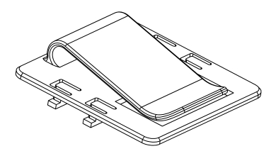
To mount an adapter plate onto an Active Puck, simply insert the four T-shaped latches of the adapter plate into the four slots on the back of an Active puck. Once the latches have been fully inserted, slide the adapter plate towards the center of the puck until you hear a click.
Once an adapter plate is latched onto an Active Puck, a removal tool must be used to detach the adapter plate. To use the removal tool, insert the four hooks on the removal tool into the four slots on the adapter plate. Then use the attached removal tool to slide and pull the adapter plate out from the Active Puck.
If any of the four adapter plate accessories do not fit for the object you are tracking, you can also use the attached CAD file to modify and 3D print customized adapter plates.
Adapter Plate CAD file (STEP):


With Diffuser: ±135°-Bare LED without diffuser: ±70°
Red (extremely low) - ~20 minutes left until power is depleted
Puck Body Dimensions
Dimensions without diffusers
Width: 96mm (~3.75”)
Length: 96mm (~3.75”)
Height: 20mm (~0.75”)
Dimensions with diffusers
Width: 104mm (~4.10”)
Length: 104mm (~4.10”
Height: 20mm (~0.75”)
Weight
2.24 oz (64g)
Attachment
Slots for (2) 7/8th inch velcro/elastic straps on the underside of the puck
¼ - 20 camera mount style thread on bottom for other convenient mounting solutions
Battery
1200 mAh Lithium polymer battery
Expected life 10 hrs at nominal operating conditions (cameras operating at 180Hz, with 500 𝞵s exposure setting). Lower frame rates or exposure times can extend battery life.
Charging
5V micro USB power source required to charge
~ 3hrs zero to full charge
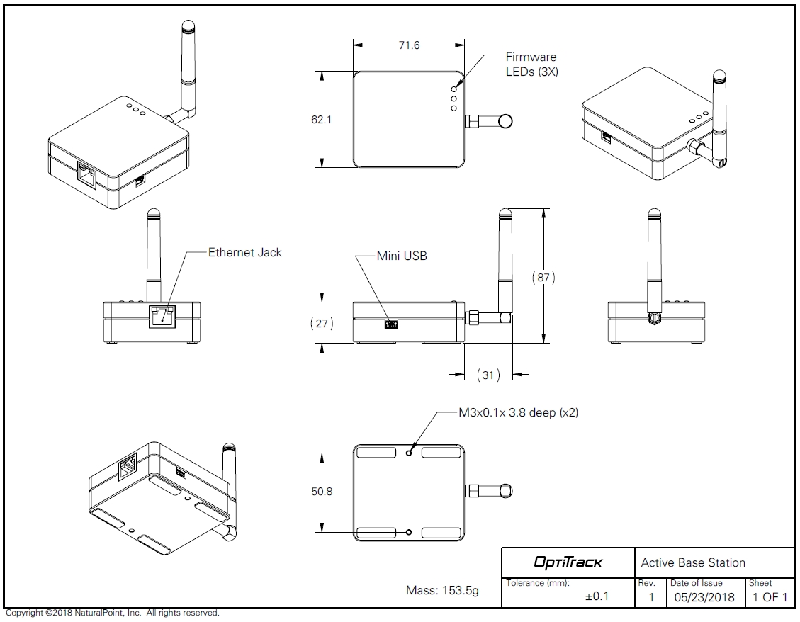
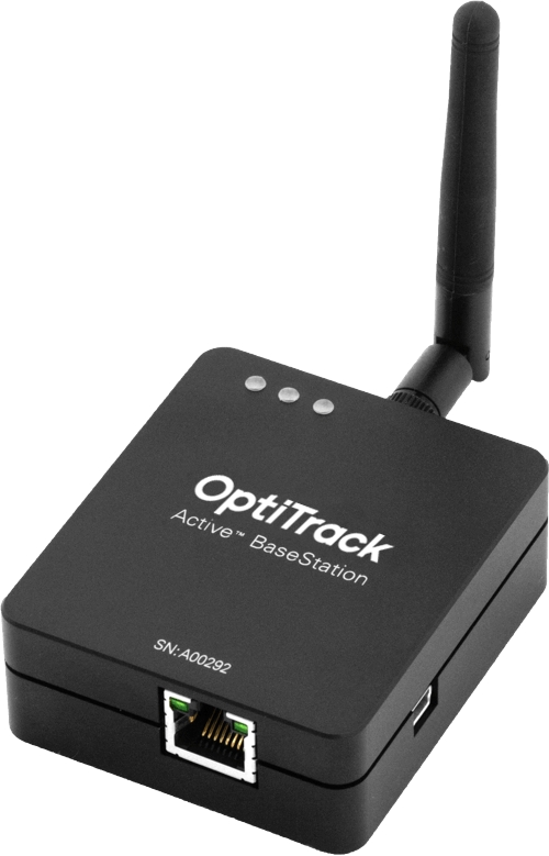
This page provides specifications for BaseStations and information about their use.
The BaseStation is the active hardware component that links other active components to Motive. Using a radio frequency channel (RF channel) between 11-26, the BaseStation synchronizes OptiTrack cameras with Active Tags and Pucks. Once the BaseStation receives the signal from the active component, it sends that data to the Motive computer along the camera network. This allows Motive to recognize Active Pucks and Tags even with significant occlusion of the LED markers, as compared to passive markers.
If you use Active Tags or Pucks, at least one BaseStation is required per tracking system.
For larger volumes, the approximate range from BaseStation to Tags/Pucks is 100’.
The number of IMUs that can attach to a BaseStation is determined by the system frame rate and the divisor applied to the BaseStation. The table below shows the IMU maximum for common frame rates with a divisor rate of 1, 2, and in some cases 3.
As noted, the table does not include all possible frame rate and divisor combinations. If you are familiar with using Tera Term or , you can determine the maximum number of IMUs for any specific frame rate and divisor combination not shown on the table.
Use PuTTy to change the divisor rate on the BaseStation.
Connect an IMU puck to PuTTy.
Attempt to set the ID of the puck to an unrealistically high value. This triggers a warning that includes the current number of slots available for the given frame rate.
Set the IMU puck ID to the highest available slot for the frame rate and confirm that it appears in Motive.
As shipped, BaseStations will connect to the OptiTrack system without additional configuration by the user. Some circumstances may require a configuration update, such as when adding new BaseStations to an existing system or when you wish to change the divisor rate.
The BaseStation is configured outside of Motive, using one of the following programs:
Please see the linked pages for more details on configuring the BaseStation.
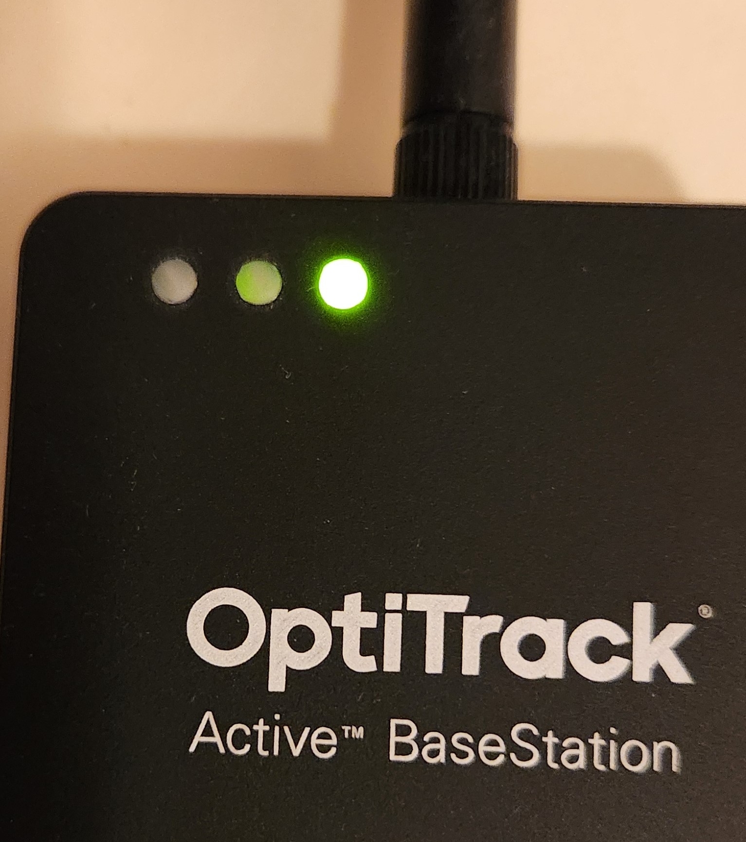
Note: Behavior of the LEDs on the BaseStation is controlled by firmware and is subject to change.
From Right to Left:
Communication Indicator LED: When the BaseStation is successfully sending data and communicating with the Active Pucks, the LED closest to the antenna will blink green. If this LED turns red, it indicates that the BaseStation failed to establish a connection with Motive.
Interference Indicator LED: The middle LED indicates if there are other signal-traffics on the respective radio channel and PAN ID that might be interfering with the active components. This LED should stay dark in order for the active marker system to work properly. If it flashes in red, consider switching both the channel and PAN ID on all of the active components.
Power Indicator LED: The LED located at the corner indicates power for the BaseStation. This LED may be disabled on BaseStations with the latest firmware, but on older BaseStations this LED may light up in red to indicate the device has power.
When connected to the OptiTrack system, the properties for any Base Station with firmware 2.x or greater and all associated active devices are shown in the Devices Pane. Please see the page for more details.
This feature requires BaseStation firmware version 2.x or greater. BaseStations and tags with version 1.x firmware will not be visible in the Devices pane but will still work with the OptiTrack system.
90
16
36
54
100
14
32
49
110
13
29
44
120
11
26
40
130
10
24
140
9
22
34
150
9
20
160
8
19
30
170
7
17
180
7
16
26
190
6
15
200
6
14
23
210
5
14
220
5
13
21
230
5
12
240
4
11
18
250
4
11
60
26
54
83
70
22
47
71
80
19
39
62
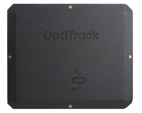
This page provides specifications and additional information for the CinePuck.
The CinePuck is designed specifically for Virtual Production or Broadcast studios. For more information on how to use the CinePuck for Virtual Production, please visit the Virtual Production section of this documentation.
The following specifications apply for active IR LEDs on the CinePuck:
850 nm IR spectrum
8 LEDs
Illuminations synchronized with camera exposures
Illumination angle: ±60°
The number of devices with IMUs (such as CinePucks) that can attach to a BaseStation is determined by the system frame rate and the divisor applied to the BaseStation. The table below shows the IMU maximum for common frame rates with a divisor rate of 1, 2, and in some cases 3.
As noted, the table does not include all possible frame rate and divisor combinations. If you are familiar with using Tera Term or , you can determine the maximum number of IMUs for any specific frame rate and divisor combination not shown on the table.
Use PuTTy to change the divisor rate on the BaseStation.
Connect an IMU puck to PuTTy.
Attempt to set the ID of the puck to an unrealistically high value. This triggers a warning that includes the current number of slots available for the given frame rate.
Set the IMU puck ID to the highest available slot for the frame rate and confirm that it appears in Motive.
To use a CinePuck in Motive, it must first be an asset. Please see the page for instructions on creating a , and the page for instruction on pairing the IMU.
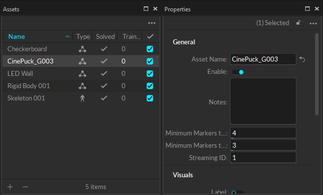
Once the CinePuck rigid body is created, it will be available in the . Select the CinePuck either in the Assets pane or the to display its properties in the .
When connected to the OptiTrack system, the properties for the CinePuck IMU and its associated BaseStation are shown in the Devices Pane. Please see the page for more details.
Watch the video below to see a demonstration of a CinePuck setup and calibration at the 4:20 mark. Please also see our for more details.
Dynamic Range
500 +/- °/sec
90
16
36
54
100
14
32
49
110
13
29
44
120
11
26
40
130
10
24
140
9
22
34
150
9
20
160
8
19
30
170
7
17
180
7
16
26
190
6
15
200
6
14
23
210
5
14
220
5
13
21
230
5
12
240
4
11
18
250
4
11
CinePuck Body Dimensions
Dimensions
Width: 153.30mm (~6.04”)
Length: 127.68mm(~5.03”)
Height: 25.70(~1.01”)
Weight
11.58 oz (~328.29g)
Attachment
x1 ARRI-Style Anti-Twist Mount w/ 3/8"-16 threads
x6 Standard Tripod Mounts w/ 1/4"-20 threads
Battery
2200mAh Lithium polymer battery
Charging
5V micro USB Type C
~7.5 hours* of battery life (*Battery life varies depending on frame rate and exposure settings)
5hrs zero to full charge
IMU
Dimensions
Width: 15mm
Length: 15mm
Height: 5.720mm
Weight
< 1.75g
60
26
54
83
70
22
47
71
80
19
39
Gyroscope
62